Sign In
Upload
Manuals
Brands
Omron Manuals
Temperature Controller
E5C series
Omron E5C series Manuals
Manuals and User Guides for Omron E5C series. We have
4
Omron E5C series manuals available for free PDF download: User Manual, Connection Manual
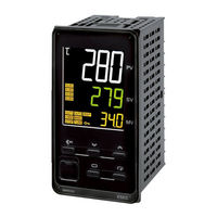
Omron E5C series User Manual (440 pages)
Digital Temperature Controllers
Brand:
Omron
| Category:
Controller
| Size: 16.37 MB
Table of Contents
Preface
3
Terms and Conditions Agreement
4
Application Considerations
5
Disclaimers
5
Safety Precautions
6
Definition of Precautionary Information
6
Symbols
6
Precautions for Safe Use
9
Installation Precautions
12
Precautions for Operation
13
Shipping Standards
13
Preparations for Use
14
Versions
15
Revision History
16
Conventions Used in this Manual
17
Model Notation
17
Meanings of Abbreviations
17
How to Read Display Symbols
18
How this Manual Is Organized
18
Related Manuals
18
Sections in this Manual
19
Table of Contents
20
Introduction
25
Appearance, Features, and Functions of the E5@C
26
Appearance
26
Features
26
Main Functions
27
I/O Configuration and Model Number Legend
29
I/O Configuration
29
Model Number Legends
30
Preparations
39
Installation
40
Dimensions (Unit: MM)
40
Panel Cutout (Unit: MM)
44
Mounting
47
Using the Terminals
62
E5CC Terminal Block Wiring Example
62
E5CC-U Terminal Block Wiring Example
67
E5CC-B Terminal Block Wiring Example
70
E5EC/E5AC Terminal Block Wiring Example
74
E5EC-B Terminal Block Wiring Example
79
E5DC Terminal Block Wiring Example
84
E5DC-B Terminal Block Wiring Example
87
E5GC Terminal Block Wiring Example
90
Precautions When Wiring
93
Wiring
99
Insulation Block Diagrams
111
Using the Setup Tool Port
114
Procedure
114
Connection Method
114
Installing the Driver
121
Basic Application Flow
124
Power on
125
Part Names, Part Functions, and Setting Levels
126
Part Names and Functions
126
Entering Numeric Values
131
Setting Levels
132
Procedures after Turning on the Power Supply
135
Basic Flow of Operations
135
Basic Procedure
135
Basic Operation
143
Moving between Setting Levels
145
Moving to the Initial Setting Level
145
Moving to the Adjustment Level
146
Moving to the Protect Level
146
Moving to the Advanced Function Setting Level
147
Moving to the Communications Setting Level
149
Initial Setting Examples
150
Setting the Input Type
153
Input Type
153
Selecting the Temperature Unit
155
Temperature Unit
155
Selecting PID Control or ON/OFF Control (Not Supported for Position-Proportional Models.)
156
Setting Output Specifications
157
Control Periods (Not Supported for Position-Proportional Models.)
157
Direct and Reverse Operation
157
Assigned Output Functions (Assigning Control Outputs Is Not Supported for Position-Proportional Models.)
158
Auxiliary Output Opening or Closing in Alarm
161
Setting the Set Point (SP)
162
Changing the SP
162
Using ON/OFF Control (Not Supported for Position-Proportional Models.)
163
ON/OFF Control
163
Hysteresis
163
Settings
164
Determining PID Constants(AT, ST, Manual Setup)
166
Determining PID Constants (AT, ST, Manual Setup)
166
AT (Auto-Tuning)
166
ST (Self-Tuning) (Not Supported for Position-Proportional Models.)
169
RT (Robust Tuning) (Used for at or ST.)
170
Manual Setup
172
Alarm Outputs
174
Alarm Types
174
Alarm Values
177
Alarm Hysteresis
180
Standby Sequence
180
Alarm Latch
181
Using Heater Burnout (HB) and Heater Short (HS) Alarms (Not Supported for Position-Proportional Models.)
182
HB Alarm
182
HS Alarm
184
Installing Current Transformers (CT)
186
Calculating Detection Current Values
188
Application Examples
188
Customizing the PV/SP Display
192
PV/SP Display Selections
192
Advanced Operations
195
Shifting Input Values
197
Setting Scaling Upper and Lower Limits for Analog Inputs
199
Executing Heating/Cooling Control (Not Supported for Position-Proportional Models.)
201
Heating/Cooling Control
201
Using Event Inputs
205
Event Input Settings
205
How to Use the Multi-SP Function
205
Operation Commands Other than Multi-SP
206
Setting the SP Upper and Lower Limit Values
209
Set Point Limiter
209
Setting
210
Using the SP Ramp Function to Limit the SP Change Rate
211
SP Ramp
211
Using the Key Protect Level
213
Protection
213
Entering the Password to Move to the Protect Level
214
Displaying Only Parameters that Have Been Changed
216
Displaying Changed Parameters
216
OR Output of Alarms
218
Integrated Alarm
218
Alarm Delays
220
Loop Burnout Alarm (Not Supported for Position-Proportional Models.)
222
Loop Burnout Alarm (LBA)
222
Performing Manual Control
226
Manual MV
226
Using the Transfer Output for the Process Value, Set Point, or Other Data
230
Transfer Output Function
230
Simple Transfer Output Function
233
Using the Simple Program Function
236
Simple Program Function
236
Operation at the Program End
239
Application Example Using a Simple Program
241
Output Adjustment Functions
242
Output Limits
242
MV at Stop
242
MV at PV Error
243
Using the Extraction of Square Root Parameter
245
Extraction of Square Roots
245
Setting the Width of MV Variation
247
MV Change Rate Limit
247
Setting the PF Key
249
PF Setting (Function Key)
249
Displaying PV/SV Status
252
PV and SV Status Display Functions
252
Using a Remote SP
254
Controlling Valves (Can be Used with a Position-Proportional Model)
256
Logic Operations
259
The Logic Operation Function (CX-Thermo)
259
Using Logic Operations
259
Using Status Display Messages
267
Initializing Settings
269
Parameters
269
Conventions Used in this Section
272
Protect Level
273
Operation Level
277
Adjustment Level
288
Monitor/Setting Item Level
308
Manual Control Level
309
Initial Setting Level
311
Advanced Function Setting Level
331
Communications Setting Level
366
User Calibration
369
7-1 User Calibration
371
Parameter Structure
371
Thermocouple Calibration
372
Resistance Thermometer Calibration
375
Calibrating Analog Input
377
Calibrating the Transfer Output
381
Checking Indication Accuracy
383
Appendices
387
Specifications
387
A-1-1 Ratings
387
A-1-2 Characteristics
387
A-1-3 Rating and Characteristics of Options
387
A-1-4 Waterproof Packing
392
Unit Labels
392
A-1-6 Setup Tool Port Cover for Front Panel
393
A-1-7 Connector Cover of the Terminal Unit (Models with Push-In Plus Terminal Blocks
394
Current Transformer (CT
396
A-2-1 Specifications
396
A-2-2 Dimensions (Unit: MM
396
USB-Serial Conversion Cable and Conversion Cable
399
A-3-1 E58-CIFQ2 USB-Serial Conversion Cable
399
A-3-2 E58-CIFQ2-E Conversion Cable
400
Error Displays
401
A-5 Troubleshooting
405
A-5-1 Frequently Asked Questions
405
A-5-2 Checking Problems
408
Parameter Operation Lists
411
A-6-1 Operation Level
411
A-6-2 Adjustment Level
412
A-6-3 Initial Setting Level
414
A-6-4 Manual Control Level
418
A-6-5 Monitor/Setting Item Level
418
A-6-6 Advanced Function Setting Level
418
A-6-7 Protect Level
424
A-6-8 Communications Setting Level
424
A-6-9 Initialization According to Parameter Changes
425
Sensor Input Setting Range, Indication Range, Control Range
429
Setting Levels Diagram
430
Parameter Flow
431
Advertisement
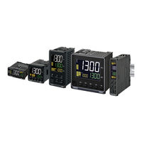
Omron E5C series User Manual (392 pages)
Digital Temperature Controllers
Brand:
Omron
| Category:
Temperature Controller
| Size: 21.28 MB
Table of Contents
Preface
3
Terms and Conditions Agreement
4
Application Considerations
5
Disclaimers
5
Performance Data
5
Safety Precautions
6
Definition of Precautionary Information
6
Symbols
6
Precautions for Safe Use
9
Installation Precautions
12
Precautions for Operation
13
Shipping Standards
13
Preparations for Use
14
Versions
15
Revision History
16
Conventions Used in this Manual
17
Model Notation
17
Meanings of Abbreviations
17
Introduction
18
How to Read Display Symbols
18
How this Manual Is Organized
18
Related Manuals
18
Sections in this Manual
19
Table of Contents
20
Introduction
25
Appearance, Features, and Functions of the E5@C
26
Appearance
26
Features
26
Main Functions
27
I/O Configuration and Model Number Legend
29
I/O Configuration
29
Model Number Legends
30
Preparations
35
Installation
36
Dimensions (Unit: MM)
36
Panel Cutout (Unit: MM)
39
Mounting
42
Removing the Main Unit
45
Removing the Digital Controller from the Case
47
Removing the Terminal Block
47
Using the Terminals
49
E5CC Terminal Block Wiring Example
49
Sensor Input
50
E5CC-U Terminal Block Wiring Example
54
E5EC/E5AC Terminal Block Wiring Example
57
E5DC Terminal Block Wiring Example
62
E5GC Terminal Block Wiring Example
65
Precautions When Wiring
68
Wiring
69
Control Output
72
Insulation Block Diagrams
78
Using the Setup Tool Port
80
Procedure
80
Connection Method
80
Installing the Driver
87
Basic Application Flow
90
Power on
91
Part Names, Part Functions, and Setting Levels
92
Part Names and Functions
92
Part Names and Basic Procedures
93
Setup Tool Ports
96
Entering Numeric Values
97
Setting Levels
98
Operation Level
99
Adjustment Level
99
Initial Setting Level
99
Advanced Function Setting Level
99
Procedures after Turning on the Power Supply
101
Basic Flow of Operations
101
Basic Procedure
101
Position-Proportional Models
103
Basic Operation
109
Moving between Setting Levels
111
Moving to the Initial Setting Level
111
Moving to the Adjustment Level
112
Moving to the Protect Level
112
Moving to the Advanced Function Setting Level
113
Moving to the Communications Setting Level
115
Initial Setting Examples
116
Basic Operation
117
Setting the Input Type
119
Input Type
119
Selecting the Temperature Unit
121
Temperature Unit
121
Selecting PID Control or ON/OFF Control (Not Supported for Position-Proportional Models.)
122
Setting Output Specifications
123
Control Periods (Not Supported for Position-Proportional Models.)
123
Direct and Reverse Operation
123
Assigned Output Functions (Assigning Control Outputs Is Not Supported for Position-Proportional Models.)
124
Assigned Output Functions
125
Auxiliary Output Opening or Closing in Alarm
127
Setting the Set Point (SP)
128
Changing the SP
128
Using ON/OFF Control (Not Supported for Position-Proportional Models.)
129
ON/OFF Control
129
Settings
130
Determining PID Constants (AT, ST, Manual Setup)
132
AT (Auto-Tuning)
132
ST (Self-Tuning) (Not Supported for Position-Proportional Models.)
134
Startup Conditions
134
RT (Robust Tuning) (Used for at or ST.)
135
St Stable Range
135
Manual Setup
137
Alarm Outputs
139
Alarm Types
139
Alarm Values
142
Pv Change Rate Alarm
143
Alarm Hysteresis
145
Standby Sequence
145
Alarm Latch
146
Using Heater Burnout (HB) and Heater Short (HS) Alarms (Not Supported for Position-Proportional Models.)
147
HB Alarm
147
HS Alarm
149
Installing Current Transformers (CT)
151
Calculating Detection Current Values
153
Application Examples
153
Customizing the PV/SP Display
157
PV/SP Display Selections
157
Shifting Input Values
161
Shifting Inputs
161
Setting Scaling Upper and Lower Limits for Analog Inputs
163
Executing Heating/Cooling Control (Not Supported for Position-Proportional Models.)
165
Heating/Cooling Control
165
Executing Heating/Cooling Control
165
Three-Position Control
168
Using Event Inputs
169
Event Input Settings
169
How to Use the Multi-SP Function
169
Operation Commands Other than Multi-SP
170
Setting the SP Upper and Lower Limit Values
173
Set Point Limiter
173
Setting
174
Using the SP Ramp Function to Limit the SP Change Rate
175
SP Ramp
175
Using the Key Protect Level
177
Protection
177
Entering the Password to Move to the Protect Level
178
Setting Change Protect
178
Displaying Only Parameters that Have Been Changed
180
Displaying Changed Parameters
180
OR Output of Alarms
182
Integrated Alarm
182
Alarm Delays
184
Loop Burnout Alarm (Not Supported for Position-Proportional Models.)
186
Loop Burnout Alarm (LBA)
186
Performing Manual Control
190
Manual MV
190
Using the Transfer Output
194
Transfer Output Function
194
Transfer Scaling
195
Simple Transfer Output Function
197
Using the Simple Program Function
200
Simple Program Function
200
Operation at the Program End
203
Application Example Using a Simple Program
205
Output Adjustment Functions
206
Output Limits
206
MV at Stop
206
MV at PV Error
207
Using the Extraction of Square Root Parameter
209
Extraction of Square Roots
209
Setting the Width of MV Variation
211
MV Change Rate Limit
211
Setting the PF Key
213
PF Setting (Function Key)
213
Displaying PV/SV Status
216
PV and SV Status Display Functions
216
Using a Remote SP
218
Controlling Valves (Can be Used with a Position-Proportional Model)
220
Logic Operations
222
The Logic Operation Function (CX-Thermo)
222
Using Logic Operations
222
Using Status Display Messages (E5GC Only)
230
Conventions Used in this Section
234
Protect Level
235
Operation Level
239
Adjustment Level
250
Monitor/Setting Item Level
270
Manual Control Level
271
Initial Setting Level
273
Advanced Function Setting Level
292
Communications Setting Level
326
User Calibration
329
User Calibration
330
7-1 User Calibration
331
Parameter Structure
331
Thermocouple Calibration
332
Resistance Thermometer Calibration
335
Calibrating Analog Input
337
Calibrating a Voltage Input
338
Calibrating the Transfer Output
340
Checking Indication Accuracy
342
Thermocouple or Infrared Temperature Sensor
342
Analog Input
344
Appendices
345
Specifications
346
A-1-1 Ratings
346
A-1-2 Characteristics
348
A-1-3 Rating and Characteristics of Options
349
A-1-4 Waterproof Packing
350
A-1-5 Unit Labels
350
A-1-6 Setup Tool Port Cover for Front Panel
351
Current Transformer (CT
352
A-2-1 Specifications
352
A-2-2 Dimensions (Unit: MM
352
USB-Serial Conversion Cable and Conversion Cable
353
A-3-1 E58-CIFQ2 USB-Serial Conversion Cable
353
A-3-2 E58-CIFQ2-E Conversion Cable
354
Error Displays
355
Troubleshooting
359
Parameter Operation Lists
362
A-6-1 Operation Level
362
A-6-2 Adjustment Level
363
Initial Setting Level
365
A-6-4 Manual Control Level
368
A-6-5 Monitor/Setting Item Level
369
A-6-6 Advanced Function Setting Level
369
A-6-7 Protect Level
375
A-6-8 Communications Setting Level
375
A-6-9 Initialization According to Parameter Changes
376
Sensor Input Setting Range, Indication Range, Control Range
379
Setting Levels Diagram
381
Parameter Flow
382
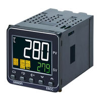
Omron E5C series User Manual (372 pages)
Digital Temperature Controllers
Brand:
Omron
| Category:
Temperature Controller
| Size: 18.59 MB
Table of Contents
Performance Data
5
Application Considerations
5
Safety Precautions
6
Definition of Precautionary Information
6
Precautions for Safe Use
11
Installation Precautions
11
Precautions for Operation
12
Revision History
15
Conventions Used in this Manual
16
Model Notation
16
Meanings of Abbreviations
16
Related Manuals
17
How to Read Display Symbols
17
How this Manual Is Organized
17
Table of Contents
20
Sections in this Manual
26
Introduction
26
Appearance, Features, and Functions of the E5@C
26
Appearance
26
Features
26
Main Functions
27
I/O Configuration and Model Number Legend
29
I/O Configuration
29
Model Number Legends
30
Preparations
35
Installation
36
Dimensions (Unit: MM)
36
Panel Cutout (Unit: MM)
39
Mounting
41
Removing the Main Unit
44
Using the Terminals
46
E5CC Terminal Block Wiring Example
46
Sensor Input
47
E5CC-U Terminal Block Wiring Example
51
E5EC/E5AC Terminal Block Wiring Example
54
E5DC Terminal Block Wiring Example
59
Precautions When Wiring
62
Wiring
62
Control Output
65
Potentiometer Input
68
Insulation Block Diagrams
71
Using the Setup Tool Port
73
Procedure
73
Connection Method
73
Installing the Driver
78
Part Names and Basic Procedures
79
Basic Application Flow
80
Power on
81
Part Names, Part Functions, and Setting Levels
82
Part Names and Functions
82
Setup Tool Ports
85
Entering Numeric Values
86
Setting Levels
87
Operation Level
88
Adjustment Level
88
Initial Setting Level
88
Advanced Function Setting Level
88
Procedures after Turning on the Power Supply
90
Basic Flow of Operations
90
Basic Procedure
90
Position-Proportional Models
92
Basic Operation
97
Basic Operation
99
Moving between Setting Levels
101
Moving to the Initial Setting Level
101
Moving to the Adjustment Level
102
Moving to the Protect Level
102
Moving to the Advanced Function Setting Level
103
Moving to the Communications Setting Level
105
Initial Setting Examples
106
Setting the Input Type
109
Input Type
109
Selecting the Temperature Unit
111
Temperature Unit
111
Selecting PID Control or ON/OFF Control (Not Supported for Position-Proportional Models.)
112
Setting Output Specifications
113
Control Periods (Not Supported for Position-Proportional Models.)
113
Direct and Reverse Operation
113
Assigned Output Functions (Assigning Control Outputs Is Not Supported for Position-Proportional Models.)
114
Assigned Output Functions
115
Auxiliary Output Opening or Closing in Alarm
117
Setting the Set Point (SP)
118
Changing the SP
118
Using ON/OFF Control (Not Supported for Position-Proportional Models.)
119
ON/OFF Control
119
Settings
120
Determining PID Constants (AT, ST, Manual Setup)4-24
122
AT (Auto-Tuning)
122
Determining PID Constants (AT, ST, Manual Setup)
122
ST (Self-Tuning) (Not Supported for Position-Proportional Models.)
124
Startup Conditions
124
RT (Robust Tuning) (Used for at or ST.)
125
St Stable Range
125
Manual Setup
127
Alarm Outputs
129
Alarm Types
129
Alarm Values
132
Pv Change Rate Alarm
133
Alarm Hysteresis
135
Standby Sequence
135
Alarm Latch
136
Using Heater Burnout (HB) and Heater Short (HS) Alarms (Not Supported for Position-Proportional Models.)
137
HB Alarm
137
HS Alarm
139
Installing Current Transformers (CT)
141
Calculating Detection Current Values
143
Application Examples
143
Customizing the PV/SP Display
147
PV/SP Display Selections
147
Shifting Input Values
151
Shifting Inputs
151
Setting Scaling Upper and Lower Limits for Analog Inputs
153
Executing Heating/Cooling Control (Not Supported for Position-Proportional Models.)
155
Heating/Cooling Control
155
Executing Heating/Cooling Control
155
Three-Position Control
158
Using Event Inputs
159
Event Input Settings
159
How to Use the Multi-SP Function
159
Operation Commands Other than Multi-SP
160
Setting the SP Upper and Lower Limit Values
163
Set Point Limiter
163
Setting
164
Using the SP Ramp Function to Limit the SP Change Rate
165
SP Ramp
165
Using the Key Protect Level
167
Protection
167
Entering the Password to Move to the Protect Level
168
Setting Change Protect
168
Displaying Only Parameters that Have Been Changed
170
Displaying Changed Parameters
170
OR Output of Alarms
172
Integrated Alarm
172
Alarm Delays
174
Loop Burnout Alarm (Not Supported for Position-Proportional Models.)
176
Loop Burnout Alarm (LBA)
176
Performing Manual Control
180
Manual MV
180
Using the Transfer Output
184
Transfer Output Function
184
Transfer Scaling
185
Using the Simple Program Function
187
Simple Program Function
187
Starting Method
188
Operation at the Program End
189
Application Example Using a Simple Program
191
Output Adjustment Functions
192
Output Limits
192
MV at Stop
192
MV at PV Error
193
Using the Extraction of Square Root Parameter
195
Extraction of Square Roots
195
Setting the Width of MV Variation
197
MV Change Rate Limit
197
Setting the PF Key
199
PF Setting (Function Key)
199
Displaying PV/SV Status
202
PV and SV Status Display Functions
202
Using a Remote SP
204
Controlling Valves (Can be Used with a Position-Proportional Model)
206
Logic Operations
208
The Logic Operation Function (CX-Thermo)
208
Using Logic Operations
208
Conventions Used in this Section
218
Protect Level
219
Operation Level
223
Adjustment Level
234
Monitor/Setting Item Level
254
Manual Control Level
255
Initial Setting Level
257
Advanced Function Setting Level
275
Communications Setting Level
308
Preparations for Use
309
Shipping Standards
309
Versions
309
User Calibration
311
User Calibration
312
7-1 User Calibration
313
Parameter Structure
313
Thermocouple Calibration
314
Resistance Thermometer Calibration
317
Calibrating Analog Input
319
Calibrating a Voltage Input
320
Calibrating the Transfer Output
321
Checking Indication Accuracy
323
Thermocouple or Infrared Temperature Sensor
323
Analog Input
325
Appendices
327
Specifications
328
A-1-1 Ratings
328
A-1-2 Characteristics
330
A-1-3 Rating and Characteristics of Options
332
A-1-4 Waterproof Packing
332
A-1-5 Unit Labels
332
A-1-6 Setup Tool Port Cover for Front Panel
333
Current Transformer (CT
334
A-2-1 Specifications
334
A-2-2 Dimensions (Unit: MM
334
USB-Serial Conversion Cable and Conversion Cable
335
A-3-1 E58-CIFQ2 USB-Serial Conversion Cable
335
A-3-2 E58-CIFQ2-E Conversion Cable
336
Error Displays
337
Troubleshooting
341
Parameter Operation Lists
344
A-6-1 Operation Level
344
A-6-2 Adjustment Level
345
Initial Setting Level
347
A-6-4 Manual Control Level
350
A-6-5 Monitor/Setting Item Level
350
A-6-6 Advanced Function Setting Level
350
A-6-7 Protect Level
356
A-6-8 Communications Setting Level
356
A-6-9 Initialization According to Parameter Changes
357
Sensor Input Setting Range, Indication Range, Control Range
360
Setting Levels Diagram
361
Parameter Flow
362
Advertisement
Omron E5C series Connection Manual (60 pages)
General-purpose Serial. RS-485 CompoWay/F. Machine Automation Controller,
Brand:
Omron
| Category:
Controller
| Size: 2.66 MB
Table of Contents
Table of Contents
3
1 Related Manuals
4
2 Terms and Definitions
4
3 Precautions
5
4 Overview
6
5 Applicable Devices and Device Configuration
7
Applicable Devices
7
Device Configuration
9
6 Serial Communications Settings
11
Parameters
11
Cable Wiring
12
7 Serial Communications Connection Procedure
13
Work Flow
13
Digital Temperature Controller Setup
14
Controller Setup
18
Serial Communication Status Check
33
8 Initialization Method
35
Initializing a Controller
35
Initializing a Digital Temperature Controller
36
9 Program
37
Overview
37
Destination Device Command
43
Error Detection Processing
46
Variables
47
ST Program
49
Timing Charts
54
Error Processing
55
10 Revision History
59
Advertisement
Related Products
OMRON E5CN
OMRON E5CN-H
OMRON E5CN-U -
OMRON E5CS-X -
OMRON E5CSV -
Omron E5CN-HT
Omron E5CZ
Omron E5CZ-U
Omron E5CS-U
Omron E5CC-U
Omron Categories
Blood Pressure Monitor
Controller
Accessories
Switch
Inverter
More Omron Manuals
Login
Sign In
OR
Sign in with Facebook
Sign in with Google
Upload manual
Upload from disk
Upload from URL