Sign In
Upload
Manuals
Brands
keysight Manuals
Measuring Instruments
N5227B
keysight N5227B Manuals
Manuals and User Guides for keysight N5227B. We have
4
keysight N5227B manuals available for free PDF download: Service Manual, Operation And Installation Manual, Configuration Manual, Security Features And Document Of Volatility
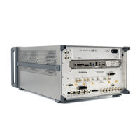
Keysight N5227B Service Manual (415 pages)
2-Port and 4-Port PNA Microwave Network Analyzers
Brand:
Keysight
| Category:
Measuring Instruments
| Size: 19.09 MB
Table of Contents
Table of Contents
3
Safety and Regulatory Information
9
Information in this Chapter
9
Chapter One At-A-Glance
9
Safety Symbols
10
General Safety Considerations
11
Safety Earth Ground
11
Before Applying Power
11
Servicing
13
Electrostatic Discharge Protection
15
Regulatory Information
17
Instrument Markings
17
Lithium Battery Disposal
18
General Product Information
19
Information in this Chapter
19
Chapter Two At-A-Glance
19
Maintenance
20
Physical Maintenance
20
Electrical Maintenance
20
Analyzer Options, Accessories, and Upgrades Available
21
Pulse I/O Adapter-N1966A
21
Required Service Test Equipment
22
Keysight Support, Services, and Assistance
24
Service and Support Options
24
Contacting Keysight
24
Shipping Your Analyzer to Keysight for Service or Repair
25
Tests and Adjustments
27
Information in this Chapter
27
Conventions Used for Hardkeys, Softkeys, and Menu Items
27
Chapter Three At-A-Glance
27
Before You Begin
30
Verify the Operating Environment
30
Protect against Electrostatic Discharge (ESD)
30
Allow the Analyzer to Warm up
31
Review the Principles of Connector Care
31
About System Verification and Performance Tests
33
System Specifications
33
Instrument Specifications
33
System Verification Procedure
34
Performance Tests
34
Certificate of Calibration
34
ANSI/NCSL Z540.3-2006 and ISO/IEC 17025 Verification
36
Non-Standards Compliant Verification
37
Preliminary Checks
38
The Operator's Check
38
The Test Port Cable Checks
40
System Verification
47
What the System Verification Verifies
47
Measurement Uncertainty
47
Measurement Traceability
48
Performing System Verification
49
Performance Tests
57
Source Power Accuracy Test
57
Source Maximum Power Output Test
58
Source Power Linearity Test
59
Frequency Accuracy Test
60
Trace Noise Test
60
Receiver Compression Test
61
Noise Floor Test
63
Calibration Coefficients Test
64
Dynamic Accuracy Test
65
Dynamic Accuracy at Low Frequency (Available with LFE Option 205/220/420/425)
66
DC Continuity Test the LFE Board and Test Ports (Available with LFE Option 205/220/420/425)
69
Adjustments
70
Touchscreen Adjustment and Verification
70
10 Mhz Frequency Reference Adjustment
71
Synthesizer Bandwidth Adjustment
73
Source Adjustment
73
IF Gain Adjustment
74
Receiver Characterization
74
Receiver Adjustment
75
EE Default Adjustment
77
IF Response Adjustment (Available Only with Option S93093/4A/B and or S93900/1/2/4/5/7A/B Installed)
77
LFE Receiver Adjustment - (Available with Option 205, 220, 405, and 420)
78
Troubleshooting
79
Information in this Chapter
79
Chapter Four At-A-Glance
80
Conventions Used for Hardkeys, Softkeys, and Menu Items
80
Operating the Analyzer with Covers Removed
81
Protect against Electrostatic Discharge (ESD)
81
Assembly Replacement Sequence
82
Getting Started with Troubleshooting
83
Check the Basics
83
Troubleshooting Organization
83
Power up Troubleshooting
85
Power Supply Check
86
Troubleshooting LCD Display Problems
91
Front Panel Troubleshooting
93
Front Panel Keypad and RPG Test
93
A3 Display Test
96
Checking the A2 USB Board
97
A1 Front Panel Interface Board
98
Rear Panel Troubleshooting
100
Checking the USB Ports
100
Checking the CONTROLLER Port
100
LAN Troubleshooting
101
Measurement System Troubleshooting
107
Before You Begin-Consider: Where Do You See a Problem
107
Verifying the A, B, C, D, and R Traces (Standard S-Parameter Mode)
108
Where to Begin Troubleshooting
110
Checking the Source Group
113
Checking the Signal Separation Group
119
2-Port Configuration, Option 210
121
2-Port Configuration, Option 219
121
2-Port Configuration, Option 220
121
4-Port Configuration, Option 400
121
Checking the Receiver Group
124
Instrument Simplified Block Diagrams - LFE
128
2-Port N5290A System Block Diagram (201 and 205)
128
2-Port N5290A System Block Diagram (202 and 205)
129
4-Port N5290A System Block Diagram (401)
130
Instrument Block Diagrams Sheet 1
133
Microwave PNA, N5227B
133
Instrument Block Diagrams Sheet 2
135
Microwave PNA, N5227B
135
Theory of Operation
137
Information in this Chapter
137
Chapter Five At-A-Glance
137
Network Analyzer System Operation
138
Functional Groups of the Network Analyzer
141
Synthesized Source Group Operation
144
Basic Operation
144
A4, A15, and A17 13.5 Ghz Synthesizer Boards
150
A5 and A10 26.5 Ghz Source Boards
151
A7, A8, A12, and A13 50 Ghz Doubler Boards
151
A56, A57, A58, and A59 70 Ghz Doubler Boards
152
A25 Multiplier/Amplifier 26.5 Board (HMA26.5)
152
A14 Frequency Reference Board
152
A23 Test Set Motherboard
153
A70 4-Port and A75 2-Port Low Frequency Extension (LFE) Board
156
Signal Separation Group Operation
167
Configurable Test Set
167
A29-A32 Receiver Couplers
168
A33-A36 Test Port Couplers
168
A38-A41 60-Db Source Step Attenuators and A471-A45 Bias Tees (Optional)
172
Receiver Group Operation
173
A46-A49 35-Db Receiver Step Attenuators (Optional)
173
A37 Reference Mixer Switch
173
A27 and A28 Mixer Bricks
173
A24 if Multiplexer Board
174
A16 SPAM Board (Analog Description)
175
Digital Processing and Digital Control Group Operation
178
Front Panel Subgroup
180
Data Acquisition and Processing Subgroup
181
Power Supply Group Operation
183
Replaceable Parts
185
Information in this Chapter
185
Chapter Six At-A-Glance
185
Ordering Information
186
Assembly Replacement Sequence
187
Rebuilt-Exchange Assemblies
188
Replaceable Parts Listings
190
Front Panel Assembly, Front Side, All Options
195
Front Panel Assembly, Back Side, All Options
198
Top Assemblies and Cables, All Options
201
2-Port Configuration, Option 200
207
2-Port Configuration, Option 201
213
4-Port Configuration, Option 401
247
4-Port Configuration, Option 405
254
4-Port Configuration, Option 410
261
4-Port Configuration, Option 419
270
4-Port Configuration, Option 420
277
Rear-Panel Assembly, All Options
301
Fan Assemblies, All Options
304
Top Hardware and Miscellaneous Parts, All Options
306
Bottom Hardware and Miscellaneous Parts
308
Internal Hardware and Miscellaneous Parts, All Options
311
External Hardware and Miscellaneous Parts, All Options
313
Miscellaneous Part Numbers
314
Repair and Replacement Procedures
319
Chapter Seven At-A-Glance
319
Personal Safety Warnings
319
Removal and Replacement Procedures
319
Removing the Covers
324
Removing and Replacing the Front Panel Assembly
325
Removing and Replacing the A4-A17 Boards
335
Removing and Replacing the A18 System Motherboard
337
Removing and Replacing the A19 Midplane Board
340
Removing and Replacing the A20 Power Supply Assembly
342
Removing and Replacing the A21 CPU Board Assembly
344
Removing and Replacing the A22 GPIB Board
347
Removing and Replacing the A23 Test Set Motherboard
348
Removing and Replacing the A24 if Multiplexer Board
351
Removing and Replacing the A26 Splitter
355
Removing and Replacing the A27 and A28 Mixer Bricks
357
Brackets
359
Removing and Replacing the A33-A36 Test Port Couplers
361
Removing and Replacing the A37 Reference Mixer Switch
363
Removing and Replacing the A42-A45 Bias Tees
368
Removing and Replacing the A55 Solid State Drive (SSD)
370
Removing and Replacing the A60-A63 70 Ghz Doublers
372
Removing and Replacing the A70 or A75 Low Frequency Extension (LFE) Board
374
Removing and Replacing the A71-A74 Bias Tee Combiners
380
Removing and Replacing the Rear Panel
384
Removing and Replacing the Front Panel LED Boards
386
Removing and Replacing the Fans
388
Removing and Replacing the Lithium Battery
390
Post-Repair Procedures
392
General Purpose Maintenance Procedures
399
Information in this Chapter
399
Chapter Eight At-A-Glance
399
Conventions Used for Hardkeys, Softkeys, and Menu Items
399
Error Terms
400
Using Error Terms as a Diagnostic Tool
400
Performing Measurement Calibration
401
Using Flowgraphs to Identify Error Terms
401
Accessing Error Terms
404
Error Term Data
406
Keysight License Manager
409
Accessing the Keysight License Manager
409
Software Entitlement Certificate
409
Enabling or Removing Options
410
Repairing and Recovering Option Data
410
Installing or Changing a Serial Number
411
Firmware Upgrades
412
How to Check the Current Firmware Version
412
Downloading from the Internet
412
Operating System Recovery
413
Recovering from Hard Disk Drive Problems
413
Correction Constants
414
Storing Correction Constants
414
Advertisement
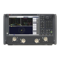
Keysight N5227B Operation And Installation Manual (100 pages)
2-Port and 4-Port Microwave Network Analyzer System
Brand:
Keysight
| Category:
Measuring Instruments
| Size: 4.1 MB
Table of Contents
Table of Contents
3
1 Safety and Regulatory Information
7
Information in this Chapter
7
Chapter One At-A-Glance
8
Safety Symbols
9
General Safety Considerations
10
Safety Earth Ground
10
Before Applying Power
10
Servicing
11
Electrostatic Discharge Protection
12
ESD Equipment Required for the Installation
13
Regulatory Information
14
Instrument Markings
14
Lithium Battery Disposal
15
EMC and Safety Information
15
N5292A Test Set Equipment Ratings
17
Environmental Requirements
18
System Heating and Cooling
18
Required Conditions for Accuracy Enhanced Measurement
19
Site Preparation
19
Power Requirements
19
2 System Description
21
Information in this Chapter
22
Chapter Two At-A-Glance
22
Introduction
23
Network Analyzer Requirements
28
Space Requirements
28
System Configurations
30
N5292A Test Set Description
31
Front Panel Features
31
Rear Panel Features
33
Interconnect Kits, Rackmount Kits, and Optional Parts
34
Banded and Non-LFE Broadband N52Xxb Millimeter System Interconnect Kits
34
Millimeter System Rackmount Kits
39
Millimeter System Optional Parts
39
Compatible Millimeter-Wave Modules
41
Basic System Measurement Configurations
46
Coaxial Measurement
46
3 System Installation
49
Information in this Chapter
50
Chapter Three At-A-Glance
50
Getting Prepared
51
Tools Required for the Installation
51
About Installing the System
51
Getting Assistance from Keysight
52
Contacting Keysight
52
Receiving the System
53
Keysight Technologies Customer Engineering
53
Review the Principles of Connector Care
54
PNA, Controller, and Test Head Module Interconnections
55
System Setup
55
Rear Panel Cabling
62
Front Panel Cabling
63
OML/VDI Millimeter-Wave Module Cable Connections
64
Configuring the PNA Software for a Self Configured System
67
Configuring Non-LFE Broadband and LFE and Non-LFE Banded Systems
67
OML/VDI and N5293A/5A Test Heads - Banded Configuration Calibration (Only)
69
Overview
69
System Hardware
69
Required Calibration Hardware
69
Overall Process
69
Detailed Procedure
70
Running the Calibrations (LO, RF, and IF)
71
LO Calibration
71
RF Calibration
74
IF Calibration
76
Initializing the Banded Millimeter-Wave System
77
Running the Installation Calibration (Broadband Systems Only)
78
Troubleshooting the OML/VDI Miilimeter Modules
81
4 Performance Verification
83
Information in this Chapter
84
Chapter Four At-A-Glance
84
Preliminary Checks
85
System Verification
85
Performing System Verification
85
If the System Verification Fails
94
5 Maintenance and Support
95
Information in this Chapter
95
Chapter Five At-A-Glance
95
Maintenance
96
Physical Maintenance
96
Electrical Maintenance
96
Caring for Waveguide (WG) Interfaces
96
Principles of Connector Care
96
Keysight Support, Services, and Assistance
98
Service and Support Options
98
Contacting Keysight
98
Shipping an Item to Keysight for Service or Repair
99
Downloading the Online System Service Guide
99
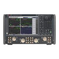
keysight N5227B Configuration Manual (47 pages)
network analyzer
Brand:
keysight
| Category:
Measuring Instruments
| Size: 4.27 MB
Table of Contents
Table of Contents
2
PNA Family Network Analyzer Configurations
5
Test Set and Power Configuration Options
5
Hardware Options
6
Application Software
7
Accessories, Calibration Options
9
PNA-X Series Test Set and Power Configuration Options
10
PNA Series Test Set and Power Configuration Options
15
PNA-L Series Test Set and Power Configuration Options
19
PNA Family Applications and Options
20
Measurement Application Software
20
Noise Figure Options and Applications
24
PNA-X Block Diagrams with Noise Figure Option
25
Noise Figure Measurement Summary
26
Pulse, Antenna, MM-Wave Applications and Options
28
Nonlinear Vector Network Analysis
28
Accessories
29
PNA Family Network Analyzer Upgrade Kits
32
Frequency, Test Ports, Test Set and Power Configurations
32
Upgrade Paths
34
Applications
35
Material Measurements
35
Signal Integrity Measurements
35
Multiport Measurements
35
Test Set Options
36
Interface Kits
36
Millimeter-Wave Measurements
36
Measurement Accessories
37
Cables and Adapter Sets
37
Calibration Kits
37
For Devices with 1.0 MM Connectors
38
For Devices with 1.85 MM Connectors
38
For Devices with 2.4 MM Connectors
39
For Devices with K Connectors (2.92 MM)
40
For Devices with 3.5 MM or SMA Connectors
42
For Devices with Type-N Connectors
44
For Devices with 7 MM Connectors
45
For Devices with Waveguide
45
Verification Kits
46
General Accessories
46
Spare Drive
46
Probe
46
Power Meters and Sensors
46
Comb Generators
47
Amplifiers
47
Couplers
47
Equipment Rack Accessories
47
Monitors
47
Interface Cables
47
Advertisement
Keysight N5227B Security Features And Document Of Volatility (34 pages)
PNA Network Analyzers
Brand:
Keysight
| Category:
Measuring Instruments
| Size: 0.47 MB
Table of Contents
Table of Contents
4
1 Contacting Keysight Sales and Service Offices
5
2 Products Covered by this Document
6
Determining Installed Options and Processor Assembly Type
7
3 Security Terms and Definitions
8
4 Non-Volatile and Volatile Memory
9
Summary of Non-Volatile Instrument Memory
10
Disk Drive Partitioning
15
CPU Types and Mass Storage
16
Summary of Volatile Memory
17
LAN/USB/GPIB Devices
19
How to Disable USB, GPIB, and LAN
19
5 Memory Sanitization and Removal Procedures
20
Instrument Sanitization Procedure
22
Application License Key Storage
22
Replacement of Disk Drive
22
Items Required
22
Procedure
23
6 Disk Drive Removal Procedure
25
7 User and Remote Interface Security Measures
28
SCPI/GPIB Control of Interfaces
28
Operating System Security Features
28
USB Interfaces
29
Disabling or Enabling Autorun/Autoplay
29
Configuring USB for Read-Only
29
8 Procedure for Declassifying a Faulty Instrument
31
Appendix A References
32
Advertisement
Related Products
Keysight N5227A
Keysight N5227BU-420
Keysight N5227-60118
Keysight N5221A
keysight N5222B
Keysight N5224AU-217
Keysight N5225AU-217
Keysight N5225-60103
Keysight N5222-60118
Keysight N5222-60119
keysight Categories
Measuring Instruments
Test Equipment
Multimeter
Control Unit
Portable Generator
More keysight Manuals
Login
Sign In
OR
Sign in with Facebook
Sign in with Google
Upload manual
Upload from disk
Upload from URL