Sign In
Upload
Manuals
Brands
FLUKE Manuals
Test Equipment
5500A
FLUKE 5500A Manuals
Manuals and User Guides for FLUKE 5500A. We have
3
FLUKE 5500A manuals available for free PDF download: Operator's Manual, Service Manual, Getting Started
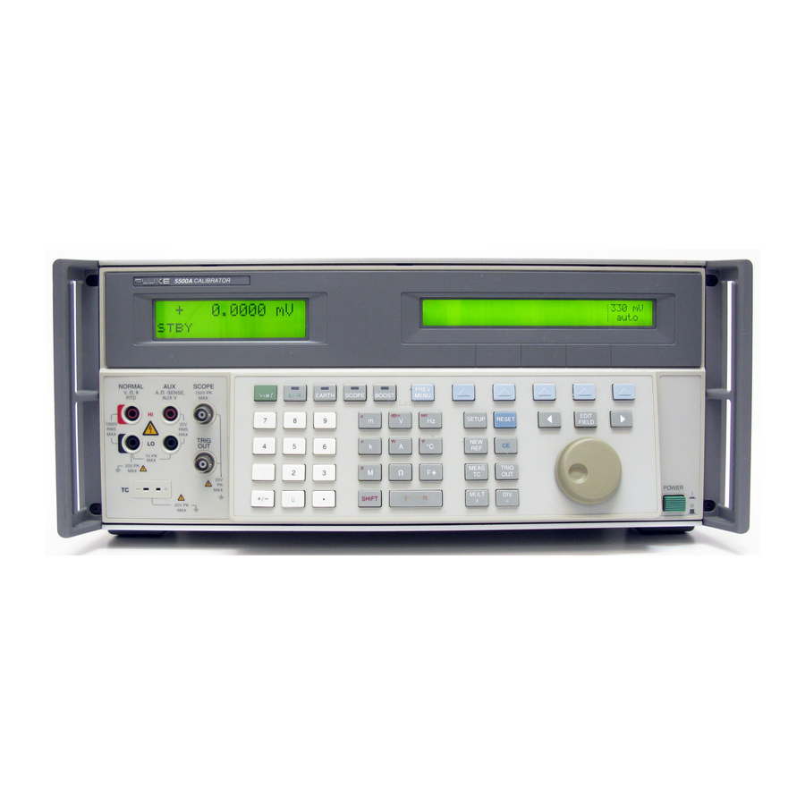
FLUKE 5500A Operator's Manual (410 pages)
Multi-Product Calibrator
Brand:
FLUKE
| Category:
Test Equipment
| Size: 3.3 MB
Table of Contents
Table of Contents
9
Introduction and Specifications
21
Introduction
23
How to Contact Fluke
24
Operation Overview
24
Local Operation
24
Remote Operation (RS-232)
24
Remote Operation (IEEE-488)
25
Where to Go from here
26
Instruction Manuals
26
5500A Operator Manual
26
5500A Operator Reference Guide
27
5500A Remote Programming Reference Guide
27
5500A Service Manual
27
5725A Amplifier
27
Specifications
29
General Specifications
30
DC Voltage Specifications
31
DC Current Specifications
32
Resistance Specifications
33
AC Voltage (Sine Wave) Specifications
34
AC Current (Sine Wave) Specifications
37
Capacitance Specifications
39
Temperature Calibration (Thermocouple) Specifications
40
Temperature Calibration (RTD) Specifications
41
DC Power Specification Summary
42
AC Power (45 Hz to 65 Hz) Specification Summary, PF=1
42
Power and Dual Output Limit Specifications
43
Phase Specifications
44
Calculating Power Uncertainty
45
Additional Specifications
46
Frequency Specifications
46
Harmonics (2 Nd to 50 Th ) Specifications
46
AC Voltage (Sine Wave) Extended Bandwidth Specifications
47
AC Voltage (Non-Sine Wave) Specifications
48
AC Voltage, DC Offset Specifications
49
AC Voltage, Square Wave Characteristics
49
AC Voltage, Triangle Wave Characteristics (Typical)
49
AC Current (Sine Wave) Extended Bandwidth Specifications
49
AC Current (Non-Sinewave) Specifications
50
AC Current (Non-Sinewave) Specifications (Cont)
51
AC Current, Square Wave Characteristics (Typical)
51
AC Current, Triangle Wave Characteristics (Typical)
51
Preparing for Operation
53
Introduction
55
Unpacking and Inspection
55
Replacing the Fuse
55
Standard Equipment
55
Selecting Line Voltage
56
Connecting to Line Power
56
Service Information
58
Line Power Cord Types Available from Fluke
58
Placement and Rack Mounting
59
Cooling Considerations
59
Connecting the 5725A Amplifier
59
Introduction
61
Features
61
Introduction
63
Front Panel Features
63
Rear Panel Features
63
Softkey Menu Trees
63
Rear Panel Features
70
Factory Default Settings for the SETUP Menus
82
Table of Contents
86
Introduction
87
Turning on the Calibrator
87
Using the Setup Menu
88
Using the Softkeys
88
Warming up the Calibrator
88
Selecting an External Amplifier
89
Using the Instrument Setup Menu
89
Using the Format EEPROM Menu
90
Utility Functions Menu
90
Factory Defaults for SETUP
91
Using the Operate and Standby Modes
92
Connecting the Calibrator to a UUT
93
Recommended Cable and Connector Types
93
When to Use EARTH
94
Four-Wire Versus Two-Wire Connections
94
Cable Connection Instructions
95
Resetting the Calibrator
91
Zeroing the Calibrator
91
UUT Connections
95
Rms Versus Peak-To-Peak Waveforms
100
Auto Range Versus Locked Range
101
Setting the Output
101
Setting DC Voltage Output
102
Setting AC Voltage Output
103
Setting DC Current Output
105
Setting AC Current Output
106
Setting DC Power Output
108
Setting AC Power Output
109
Setting a Dual DC Voltage Output
112
Setting a Dual AC Voltage Output
114
Setting Resistance Output
116
Setting Capacitance Output
117
Setting Temperature Simulation (Thermocouple)
119
Setting Temperature Simulation (RTD)
121
Measuring Thermocouple Temperatures
123
Waveform Types
124
Sinewave
125
Trianglewave
125
Squarewave
125
Truncated Sinewave
126
Setting Harmonics
126
Adjusting the Phase
127
Entering a Phase Angle
128
Entering a Power Factor
129
Entering a DC Offset
130
Using the 5725A Amplifier
131
5725A Amplifier Output
132
Editing and Error Output Settings
133
Editing the Output Setting
133
Keys that Exit Error Mode
133
Displaying the Output Error
134
Using Multiply and Divide
134
Setting Output Limits
134
Setting Voltage and Current Limits
135
Sample Applications
136
Calibrating an 80 Series Handheld Multimeter
136
Cables
136
EARTH Connection
136
Testing the Meter
137
Calibrating the Meter
141
Testing a Model 41 Power Harmonics Analyzer
142
Testing Watts, VA, VAR Performance
142
Watts Performance, Text Screen
143
Testing Harmonics Volts Performance
144
Harmonics Performance for Volts, Harmonics Screen
144
Testing Harmonics Amps Performance
145
Calibrating a Fluke 51 Thermometer
145
Harmonics Performance for AMPS, Harmonics Screen
145
Testing the Thermometer
146
Calibrating the Thermometer
147
Thermocouple Performance
147
Chapter 5 Remote Operation
149
Remote Operation
151
Introduction
152
Setting up the IEEE-488 Port for Remote Control
152
IEEE-488 Port Setup Procedure
155
Testing the IEEE-488 Port
156
Host Port Setup Procedure
158
Setting up the RS-232 Host Port for Remote Control
158
Testing RS-232 Host Port Operation Using a Terminal
160
Testing the RS-232 Host Port
160
Testing RS-232 Host Port Operation Using Visual Basic
162
Setting up the RS-232 UUT Port for Remote Control
163
UUT Port Setup Procedure
163
Testing the RS-232 UUT Port Via RS-232 Host Port
165
Testing RS-232 UUT Port Operation Via a Terminal
165
Testing RS-232 UUT Port Operation Using Visual Basic
166
Testing the RS-232 UUT Port Via IEEE-488 Port
167
Changing between Remote and Local Operation
169
Local State
169
Local with Lockout State
169
Remote State
169
Remote with Lockout State
169
Interface Overview
170
RS-232 Interface Overview
170
IEEE-488 Interface Overview
171
Types of Commands
173
Device-Dependent Commands
173
Common Commands
174
Query Commands
174
Interface Messages (IEEE-488)
174
Compound Commands
176
Coupled Commands
176
Overlapped Commands
177
Sequential Commands
177
Commands that Require the Calibration Switch to be Enabled
177
Commands for RS-232 Only
177
Commands for IEEE-488 Only
178
Using Commands
173
Command Syntax
179
Parameter Syntax Rules
179
Extra Space or Tab Characters
180
Terminators
181
Incoming Character Processing
181
Response Message Syntax
182
Checking 5500A Status
183
Serial Poll Status Byte (STB)
183
Service Request (SRQ) Line
185
Service Request Enable Register (SRE)
185
Programming the STB and SRE
186
Event Status Register (ESR)
186
Event Status Enable (ESE) Register
186
Bit Assignments for the ESR and ESE
186
Programming the ESR and ESE
187
Bit Assignments for the ISR, ISCR, and ISCE
188
Instrument Status Change Enable Registers
188
Instrument Status Register (ISR)
188
Instrument Status Change Registers
188
Output Queue
190
Programming the ISR, ISCR, and ISCE
190
Error Queue
191
Guidelines for Programming the Calibrator
191
Remote Program Examples
191
Writing an SRQ and Error Handler
192
Using *OPC?, *OPC, and *WAI
193
Verifying a Meter on the IEEE-488 Bus
193
Verifying a Meter on the RS-232 UUT Serial Port
193
Taking a Thermocouple Measurement
194
Using the RS-232 UUT Port to Control an Instrument
194
Input Buffer Operation
195
Command Summary by Function
197
Introduction
199
Command Summary by Function
199
Summary of Commands and Queries
204
Remote Commands
197
Chapter 7 Maintenance
247
Maintenance
247
Introduction
249
Replacement Fuses
249
Cleaning the Air Filter
250
General Cleaning
252
Performing a Calibration Check
252
Replacing the Line Fuse
249
Required Equipment for Checking Calibration
252
Performance Tests
253
DC Voltage Amplitude Accuracy (NORMAL)
253
Performing a Calibration Check
253
DC Voltage Amplitude Accuracy (AUX)
254
DC Current Amplitude Accuracy
255
Resistance Accuracy
256
Resistance DC Offset Measurement
257
AC Voltage Amplitude Accuracy (NORMAL)
258
AC Voltage Amplitude Accuracy (AUX)
259
AC Current Amplitude Accuracy
260
Capacitance Accuracy
262
Thermocouple Measurement Accuracy
263
Thermocouple Sourcing Accuracy
263
Thermocouple Measuring Accuracy
263
DC Power Amplitude Accuracy (NORMAL)
264
DC Power Amplitude Accuracy (AUX)
264
AC Power Amplitude Accuracy (High Voltage)
265
AC Power Amplitude Accuracy (High Current)
265
AC Power Amplitude Accuracy (High Power)
266
Phase and Frequency Accuracy
267
AC Voltage Amplitude Accuracy, Squarewave (NORMAL)
268
AC Voltage Amplitude Accuracy, Squarewave (AUX)
269
AC Voltage Harmonic Amplitude Accuracy (NORMAL)
270
AC Voltage Harmonic Amplitude Accuracy (AUX)
271
DC Voltage Offset Accuracy
271
AC Voltage Accuracy with a DC Offset
272
Non-Operator Fuse Replacement
272
Non-Operator Fuse Replacement Locations
272
Oscilloscope Calibration Options
273
5500A-Sc600 Option
275
Introduction
277
SC600 Option Specifications
277
Volt Specifications
278
Edge Specifications
279
Leveled Sine Wave Specifications
280
Time Marker Specifications
281
Wave Generator Specifications
281
Pulse Generator Specifications
282
Trigger Signal Specifications
283
Trigger Signal Specifications (Edge Function)
283
Trigger Signal Specifications (Pulse Function)
283
Trigger Signal Specifications (Square Wave Voltage Function)
283
Trigger Signal Specifications (Time Marker Function)
283
Oscilloscope Input Capacitance Measurement Specifications
284
Oscilloscope Input Resistance Measurement Specifications
284
Overload Measurement Specifications
284
Oscilloscope Connections
285
Starting the SC600 Option
285
Adjusting the Output Signal
286
Keying in a Value
286
Adjusting Values with the Rotary Knob
287
Using and
287
The Output Signal
286
Resetting the SC600 Option
287
Calibrating the Voltage Amplitude on an Oscilloscope
288
The VOLT Function
288
The V/DIV Menu
289
Shortcuts for Setting the Voltage Amplitude
289
Oscilloscope Amplitude Calibration Procedure
290
Calibrating the Pulse and Frequency Response on an Oscilloscope
291
The Edge Function
291
Oscilloscope Pulse Response Calibration Procedure
292
Pulse Response Calibration Using a Tunnel Diode Pulser
293
The Leveled Sine Wave Function
293
Shortcuts for Setting the Frequency and Voltage
294
The more OPTIONS Menu
295
Oscilloscope Frequency Response Calibration Procedure
296
Sweeping through a Frequency Range
296
Calibrating the Time Base of an Oscilloscope
298
The Time Marker Function
298
Time Base Marker Calibration Procedure for an Oscilloscope
299
Testing the Trigger
300
Testing Video Triggers
302
Verifying Pulse Capture
303
Input Impedance Measurement
304
Measuring Input Resistance and Capacitance
304
Testing Overload Protection
305
Input Capacitance Measurement
305
Remote Commands and Queries
306
General Commands
307
Edge Function Commands
310
Marker Function Commands
310
Video Function Commands
310
Overload Function Commands
311
Impedance/Capacitance Function Commands
312
DC Voltage Verification
313
Verification Tables
313
AC Voltage Amplitude Verification
314
AC Voltage Frequency Verification
314
Wave Generator Amplitude Verification: 1 M Output Impedance
315
Wave Generator Amplitude Verification: 50 Output Impedance
316
Leveled Sinewave Verification: Amplitude
317
Leveled Sinewave Verification: Frequency
317
Leveled Sinewave Verification: Harmonics
318
Leveled Sinewave Verification: Flatness
319
Edge Verification: Amplitude
325
Edge Verification: Duty Cycle
325
Edge Verification: Frequency
325
Edge Verification: Rise Time
326
Tunnel Diode Pulser Verification
326
Marker Generator Verification
327
Pulse Generator Verification: Period
327
Pulse Generator Verification: Pulse Width
327
Input Impedance Verification: Capacitance
328
Input Impedance Verification: Resistance
328
5500A-Sc300 Option
329
Introduction
331
Oscilloscope Calibration Option Specifications
332
Volt Function Specifications
332
Edge Function Specifications
333
Leveled Sine Wave Function Specifications
334
Time Marker Function Specifications
335
Wave Generator Specifications
335
Trigger Signal Specifications for the Edge Function
336
Trigger Signal Specifications for the Time Marker Function
336
Oscilloscope Connections
337
Starting the Oscilloscope Calibration Option
338
The Output Signal
338
Adjusting the Output Signal
339
Adjusting Values with the Rotary Knob
339
Starting the Oscilloscope Calibration Option
339
Keying in a Value
339
Resetting the Oscilloscope Option
340
Calibrating the Voltage Amplitude on an Oscilloscope
341
The Volt Function
341
The V/DIV Menu
342
Shortcuts for Setting the Voltage Amplitude
342
Amplitude Calibration Procedure for an Oscilloscope
343
Calibrating the Pulse and Frequency Response on an Oscilloscope
344
The Edge Function
344
Pulse Response Calibration Procedure for an Oscilloscope
345
Shortcuts for Setting the Frequency and Voltage
346
The Leveled Sine Wave Function
346
The more OPTIONS Menu
347
Sweeping through a Frequency Range
349
Frequency Response Calibration Procedure for an Oscilloscope
350
Calibrating the Time Base of an Oscilloscope
352
The Time Marker Function
352
Time Base Marker Calibration Procedure for an Oscilloscope
353
Testing the Trigger
354
Summary of Commands and Queries
355
Voltage Function Verification: AC Voltage into a 1 M Load
358
Verification Tables
358
Load
359
Voltage Function Verification: AC Voltage into a
359
Voltage Function Verification: DC Voltage into a 50 Load
359
Voltage Function Verification: DC Voltage into a 1 M Load
361
Edge Function Verification
362
Load
362
Wave Generator Function Verification
362
Leveled Sinewave Function Verification: Amplitude
363
Leveled Sinewave Function Verification: Flatness
364
Leveled Sinewave Function Verification: Frequency
367
Marker Generator Function Verification
368
Options and Accessories
371
Introduction
371
A Amplifier Accessory
372
A/Leads
372
IEEE-488 Interface Cables
372
Rack Mount Kit
372
RS-232 Modem Cables
372
RS-232 Null-Modem Cables
372
Appendix
375
Glossary
375
ASCII and IEEE-488 Bus Codes
385
RS-232/IEEE-488 Cables and Connectors
389
Creating a Visual Basic Test Program
393
Error Message
397
Advertisement
Fluke 5500A Service Manual (296 pages)
Multi-Product Calibrator
Brand:
Fluke
| Category:
Test Equipment
| Size: 13.03 MB
Table of Contents
Table of Contents
3
Introduction and Specifications
15
Introduction
17
Service Information
18
Specifications
18
General Specifications
20
DC Voltage Specifications
21
DC Current Specifications
22
Resistance Specifications
23
AC Voltage (Sinewave) Specifications
24
AC Current (Sinewave) Specifications
27
Capacitance Specifications
29
Temperatore Calibration (Thermocouple) Specifications
30
Temperature Calibration (RTD) Specifications
31
DC Power Specification Summary
33
AC Power (45 Hz to 65 Hz) Specification Summary, PF=1
34
Power and Dual Output Limit Specifications
35
5500A Phase Specifications
35
Calculating Power Uncertainty
37
Additional Specifications
38
Frequency Specifications
38
Harmonics (2Nd to 50Th) Specifications
39
AC Voltage (Sinewave) Extended Bandwidth Specifications
40
AC Voltage (Non-Sinewave) Specifications
41
AC Voltage, DC Offset Specifications
42
AC Voltage, Squarewave Characteristics
43
AC Voltage, Trianglewave Characteristics (Typical)
43
AC Current (Sinewave) Extended Bandwidth Specifications
43
AC Current (Non-Sinewave) Specifications
44
AC Current, Squarewave Characteristics (Typical)
45
AC Current, Trianglewave Characteristics (Typical)
45
Theory of Operation
47
Chapter 2
49
Introduction
49
Encoder Assembly (A2)
50
Synthesized Impedance Assembly (A5)
50
DDS Assembly (A6)
51
Current Assembly (A7)
52
Voltage Assembly (A8)
53
Main CPU Assembly (A9)
54
Power Supplies
54
Outguard Supplies
54
Inguard Supplies
54
Calibration and Verification
55
Chapter 3
57
Introduction
57
Calibration
57
Equipment Required for Calibration and Verification
57
Starting Calibration
58
How the Calibration Procedure Works
58
DC Volts
59
AC Volts
59
Thermocouple Measuring
60
DC Current
61
AC Current
62
AUX DC Volts
62
AUX AC Volts
63
Resistance
63
Resistance Calibration Steps
64
Capacitance
66
Capacitance Calibration Steps
67
Capacitance, Four-Wire Comp
68
Frequency
68
NORMAL Volts and AUX Volts Phase
69
Volts and AUX Current Phase
69
Remote Commands for 5500A Calibration
70
Jumping to a Specific Calibration Step
71
Generating a Calibration Report
72
Calibration Shifts Report, Printout Format
72
Calibration Shifts Report, Spreadsheet Format
73
Calibration Constant Report, Printout Format
73
Calibration Constants Report, Spreadsheet Format
74
Performance Verification Tests
74
Zeroing the Calibrator
74
DC Voltage Amplitude Accuracy (NORMAL)
75
DC Voltage Amplitude Accuracy (AUX)
75
DC Current Amplitude Accuracy
76
Resistance Accuracy
77
Resistance DC Offset Measurement
78
AC Voltage Amplitude Accuracy (NORMAL)
79
AC Voltage Amplitude Accuracy (AUX)
81
AC Current Amplitude Accuracy
82
Capacitance Accuracy
83
Capacitance Accuracy Test
84
Thermocouple Measurement Accuracy
85
Thermocouple Sourcing Accuracy
85
Thermocouple Measuring Accuracy
85
DC Power Amplitude Accuracy (NORMAL)
86
DC Power Amplitude Accuracy (AUX)
86
AC Power Amplitude Accuracy (High Voltage)
87
AC Power Amplitude Accuracy (High Current)
87
AC Power Amplitude Accuracy (High Power)
88
Phase and Frequency Accuracy
88
Frequency Accuracy Test
89
AC Voltage Amplitude Accuracy, Squarewave (NORMAL)
90
AC Voltage Amplitude Accuracy, Squarewave (AUX)
91
AC Voltage Harmonic Amplitude Accuracy (NORMAL)
92
AC Voltage Harmonic Amplitude Accuracy (AUX)
93
DC Voltage Offset Accuracy
93
AC Voltage Accuracy with a DC Offset
94
Maintenance
97
Chapter 4
99
Introduction
99
Access Procedures
99
Removing Analog Modules
99
Removing the Main CPU (A9)
99
Removing Rear Panel Assemblies
100
Removing the Filter PCA (A12)
100
Removing the Encoder (A2) and Display Pcas
100
Removing the Keyboard and Accessing the Output Block
100
Diagnostic Testing
103
Running Diagnostics
103
Sequence of Diagnostics Tests
103
Diagnostics Error Messages
103
Testing the Front Panel
109
Internal Fuse Replacement
110
Complete List of Error Messages
110
List of Replaceable Parts
115
Introduction
117
How to Obtain Parts
117
How to Contact Fluke
117
Parts Lists
118
Chassis Assembly
119
Front Panel Assembly
122
Rear Panel Assembly
124
Oscilloscope Calibration Options
127
SC600 Option
129
Chapter 6
131
Introduction
131
Maintenance
131
SC600 Specifications
132
Volt Specifications
132
Edge Specifications
133
Leveled Sine Wave Specifications
134
Time Marker Specifications
135
Wave Generator Specifications
135
Pulse Generator Specifications
136
Trigger Signal Specifications (Pulse Function)
136
Trigger Signal Specifications (Time Marker Function)
136
Trigger Signal Specifications (Edge Function)
137
Trigger Signal Specifications (Square Wave Voltage Function)
137
Trigger Signal Specifications
137
Oscilloscope Input Resistance Measurement Specifications
137
Oscilloscope Input Capacitance Measurement Specifications
137
Overload Measurement Specifications
138
Theory of Operation
138
Voltage Mode
138
Edge Mode
138
Leveled Sine Wave Mode
138
Time Marker Mode
139
Wave Generator Mode
139
Input Impedance Mode (Resistance)
139
Input Impedance Mode (Capacitance)
139
Overload Mode
139
Equipment Required for Calibration and Verification
141
SC600 Calibration Setup
143
Calibration and Verification of Square Wave Voltage Functions
144
Overview of HP3458A Operation
144
Setup for SC600 Voltage Square Wave Measurements
144
Voltage HP3458A Settings
145
Setup for SC600 Edge and Wave Gen Square Wave Measurements
146
DC Voltage Calibration
147
AC Voltage Calibration
147
Wave Generator Calibration
148
Edge Amplitude Calibration
148
Leveled Sine Wave Amplitude Calibration
149
Leveled Sine Wave Flatness Calibration
150
Low Frequency Calibration
150
High Frequency Calibration
151
Pulse Width Calibration
151
Measz Calibration
152
Verification
154
DC Voltage Verification
155
Verification at 1 MΩ
155
Verification at 50 Ω
155
AC Voltage Amplitude Verification
157
Verification at 1 MΩ
157
Verification at 50 Ω
159
AC Voltage Frequency Verification
160
Edge Amplitude Verification
161
Edge Frequency Verification
161
Edge Duty Cycle Verification
162
Edge Rise Time Verification
162
Edge Abberation Verification
164
Tunnel Diode Pulser Drive Amplitude Verification
165
Leveled Sine Wave Amplitude Verification
166
Leveled Sine Wave Frequency Verification
167
Leveled Sine Wave Harmonics Verification
168
Leveled Sine Wave Harmonics Verification
169
Leveled Sine Wave Flatness Verification
170
Equipment Setup for Low Frequency Flatness
170
Equipment Setup for High Frequency Flatness
170
Low Frequency Verification
172
High Frequency Verification
172
High Frequency Flatness Verification at 5.5 V
173
High Frequency Flatness Verification at 7.5 MV
174
High Frequency Flatness Verification at 70 MV
175
High Frequency Flatness Verification at 800 MV
176
Time Marker Verification
177
Wave Generator Verification
178
Verification at 1 MΩ
178
Verification at 50 Ω
179
Pulse Width Verification
182
Measz Resistance Verification
183
Pulse Period Verification
183
Measz Capacitance Verification
184
Overload Function Verification
185
Adjusting the Leveled Sine Wave Function
186
Equipment Setup
187
Adjusting the Leveled Sine Wave VCO Balance
187
Adjusting the Leveled Sine Wave Harmonics
188
Equipment Required
186
SC600 Hardware Adjustments
186
Adjusting the Aberrations for the Edge Function
188
Equipment Setup
189
Adjusting the Edge Aberrations
189
SC300 Option
191
Introduction
193
Maintenance
193
SC300 Specifications
194
Voltage Function Specifications
194
Edge Function Specifications
195
Leveled Sine Wave Function Specifications
196
Time Marker Function Specifications
197
Wave Generator Specifications
197
Edge Mode
198
Leveled Sine Wave Mode
198
Theory of Operation
198
Time Marker Mode
198
Trigger Signal Specifications for the Edge Function
198
Trigger Signal Specifications for the Time Marker Function
198
Voltage Mode
198
Wave Generator Mode
199
Equipment Required for Calibration and Verification
201
SC300 Calibration Setup
203
Calibration and Verification of Square Wave Functions
204
Overview of HP3458A Operation
204
Setup for Square Wave Measurements
204
DC Voltage Calibration
205
AC Square Wave Voltage Calibration
206
Edge Amplitude Calibration
207
Leveled Sine Wave Amplitude Calibration
207
Leveled Sine Wave Flatness Calibration
208
High Frequency Calibration
209
Low Frequency Calibration
209
DC Voltage Verification
210
Verification
210
Verification at 1 MΩ
210
Verification at 50 Ω
210
DC Voltage Verification at 1 MΩ
211
DC Voltage Verification at 50 Ω
212
AC Voltage Amplitude Verification
213
Verification at 1 MΩ
213
Verification at 50 Ω
215
AC Voltage Frequency Verification
216
Edge Amplitude Verification
217
Edge Frequency Verification
218
Edge Duty Cycle Verification
219
Edge Rise Time Verification
219
Edge Abberation Verification
221
Leveled Sine Wave Reference Verification
222
Leveled Sine Wave Frequency Verification
223
Leveled Sine Wave Harmonics Verification
224
Leveled Sine Wave Harmonics Verification
225
Equipment Setup for High Frequency Flatness
226
Equipment Setup for Low Frequency Flatness
226
Leveled Sine Wave Flatness Verification
226
High Frequency Verification
228
Low Frequency Verification
228
High Frequency Flatness Verification at 5.5 V
229
High Frequency Flatness Verification at 7.5 MV
230
High Frequency Flatness Verification at 70 MV
231
High Frequency Flatness Verification at 800 MV
232
Time Marker Verification
233
Wave Generator Verification
234
Verification at 1 MΩ
235
Verification at 50 Ω
235
SC300 Hardware Adjustments
237
Equipment Required
238
Adjusting the Leveled Sine Wave Function
238
Equipment Setup
238
Adjusting the Leveled Sine Wave Harmonics
238
Adjusting the Aberrations for the Edge Function
239
Equipment Setup
239
Adjusting the Edge Aberrations
239
SC300 Hardware Adjustments for the A4 Board
241
Equipment Required
241
Adjusting the Leveled Sine Wave Function
241
Equipment Setup
241
Adjusting the Leveled Sine Wave VCO Balance
241
Adjusting the Leveled Sine Wave Harmonics
242
Adjusting the Aberrations for the Edge Function
243
Equipment Setup
243
Adjusting the Edge Aberrations for Board 5500A-4004-1
244
Adjusting the Edge Aberrations for Board 5500A-4004
246
Adjusting the Rise Time for the Edge Function
248
Equipment Setup
248
Adjusting the Edge Rise Time
248
Index
249
Fluke 5500A Getting Started (46 pages)
Brand:
Fluke
| Category:
Test Equipment
| Size: 0.46 MB
Table of Contents
Getting Started
1
Table of Contents
9
Introduction
11
Instruction Manuals
12
5500A Getting Started Manual
13
5500A Operator Manual
13
5500A Operator Reference Guide
13
5500A Programmer Reference Guide
13
5500A Service Manual
13
Where to Go from here
13
Operation Overview
14
Local Operation
14
Remote Operation (RS-232)
14
Remote Operation (IEEE-488)
14
Preparing for Operation
15
Unpacking and Inspection
15
Replacing the Fuse
16
Selecting Line Voltage
16
Connecting to Line Power
17
Service Information
19
Placement and Rack Mounting
19
Cooling Considerations
19
5725A Amplifier
20
Connecting the 5725A Amplifier
20
Specifications
21
General Specifications
22
DC Voltage Specifications
23
DC Current Specifications
24
Resistance Specifications
25
AC Voltage (Sinewave) Specifications
26
AC Current (Sinewave) Specifications
28
Capacitance Specifications
30
Temperature Calibration (Thermocouple) Specifications
31
Temperature Calibration (RTD) Specifications
32
DC Power Specification Summary
34
AC Power (45 Hz to 65 Hz) Specification Summary, PF=1
35
Power and Dual Output Limit Specifications
36
5500A Phase Specifications
37
Calculating Power Uncertainty
38
Additional Specifications
39
Frequency Specifications
39
Harmonics (2Nd to 50Th) Specifications
40
AC Voltage (Sinewave) Extended Bandwidth Specifications
41
AC Voltage (Non-Sinewave) Specifications
42
AC Voltage, DC Offset Specifications
43
AC Voltage, Squarewave Characteristics
43
AC Voltage, Triangle Wave Characteristics (Typical)
44
AC Current (Sinewave) Extended Bandwidth Specifications
44
AC Current (Non-Sinewave) Specifications
44
AC Current (Non-Sinewave) Specifications
45
AC Current, Squarewave Characteristics (Typical)
45
AC Current, Trianglewave Characteristics (Typical)
45
Advertisement
Advertisement
Related Products
Fluke 5502E
Fluke 5502A
Fluke 5500E
Fluke 5514B-70M
Fluke 5522A-PQ
Fluke 5522A-PQ/1G
Fluke 5522A-PQ/6
Fluke 5550A
Fluke 5540A
Fluke 5592405
FLUKE Categories
Measuring Instruments
Test Equipment
Multimeter
Thermometer
Laboratory Equipment
More FLUKE Manuals
Login
Sign In
OR
Sign in with Facebook
Sign in with Google
Upload manual
Upload from disk
Upload from URL