
Subscribe to Our Youtube Channel
Related Manuals for Fluke 5500A


Summary of Contents for Fluke 5500A
-
Page 1: Getting Started
® 5500A Multi-Product Calibrator Getting Started PN 945159 August 2001 © 2001 Fluke Corporation. All rights reserved. Printed in U.S.A. All product names are trademarks of their respective companies. - Page 2 Parts, product repairs and services are warranted for 90 days. This warranty extends only to the original buyer or end-user customer of a Fluke authorized reseller, and does not apply to fuses, disposable batteries or to any product which, in Fluke’s opinion, has been misused, altered, neglected or damaged by accident or abnormal conditions of operation or handling.
- Page 3 à appliquer une garantie plus étendue ou différente au nom de Fluke. Le support de garantie est offert si le produit a été acquis par l'intermédiaire d'un point de vente agréé par Fluke ou bien si l'acheteur a payé le prix international applicable.
- Page 4 Garantiefrist einem von Fluke autorisierten Servicezentrum zur Reparatur übergeben wird. Um die Garantieleistung in Anspruch zu nehmen, wenden Sie sich bitte an das nächstgelegene und von Fluke autorisierte Servicezentrum oder senden Sie das Produkt mit einer Beschreibung des Problems und unter Vorauszahlung von Fracht- und Versicherungskosten (FOB Bestimmungsort) an das nächstgelegene und von Fluke...
- Page 5 GARANTÍA LIMITADA Y LIMITACIÓN DE RESPONSABILIDAD Se garantiza que cada uno de los productos de Fluke no tiene defectos de material y mano de obra si es objeto de una utilización y un mantenimiento normales. El período de garantía es de un año y comienza a partir de la fecha de envío.
- Page 6 20402. Stock No. 004-000-00345-4. Declaration of the Manufacturer or Importer We hereby certify that the Fluke Model 5500A is in compliance with BMPT Vfg 243/1991 and is RFI suppressed. The normal operation of some equipment (e.g. signal generators) may be subject to specific restrictions.
- Page 7 SAFETY TERMS IN THIS MANUAL This instrument has been designed and tested in accordance with IEC publication 1010-1 (1992-1), Safety Requirements for Electrical Measuring, Control and Laboratory Equipment, and ANSI/ISA-582.01-1994, and CAN/CSA-C22.2 No. 1010.1-92. This User Manual contains information, warning, and cautions that must be followed to ensure safe operation and to maintain the instrument in a safe condition.
- Page 8 USE THE PROPER POWER CORD Use only the power cord and connector appropriate for the voltage and plug configuration in your country. Use only a power cord that is in good condition. Refer power cord and connector changes to qualified service personnel. DO NOT OPERATE IN EXPLOSIVE ATMOSPHERES To avoid explosion, do not operate the instrument in an atmosphere of explosive gas.
-
Page 9: Table Of Contents
Table of Contents Title Page Introduction ....................... 1 Instruction Manuals ................... 2 5500A Getting Started Manual ..............3 5500A Operator Manual ................3 5500A Operator Reference Guide..............3 5500A Programmer Reference Guide ............3 5500A Service Manual.................. 3 Where to Go from Here ..................3 Operation Overview .................. - Page 10 5500A Getting Started 5500A Phase Specifications................27 Calculating Power Uncertainty ..............28 Additional Specifications .................. 29 Frequency Specifications ................29 Harmonics (2nd to 50th) Specifications............30 AC Voltage (Sinewave) Extended Bandwidth Specifications ...... 31 AC Voltage (Non-Sinewave) Specifications..........32 AC Voltage, DC Offset Specifications ............33 AC Voltage, Squarewave Characteristics .............
-
Page 11: Introduction
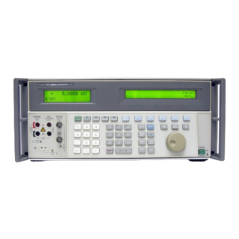
Getting Started Introduction The Fluke Model 5500A Multi-Product Calibrator (Figure 1) is a precise instrument that calibrates a wide variety of electrical measuring instruments. With the 5500A Calibrator, you can calibrate precision multimeters that measure ac or dc voltage, ac or dc current, ac or dc power, resistance, capacitance, and temperature. -
Page 12: Instruction Manuals
5500A Getting Started The 5500A Calibrator is a fully programmable precision source of the following: • DC voltage from 0 V to +1020 V. • AC voltage from 1 mV to 1020 V, with output from 10 Hz to 500 kHz. -
Page 13: 5500A Getting Started Manual
This guide is included with this manual. 5500A Service Manual The 5500A Service Manual is available in PDF format on the CD-ROM provided with your instrument. It can also be ordered through your local Fluke Sales or Service representative. -
Page 14: Operation Overview
Getting Started Operation Overview The 5500A Calibrator may be operated at the front panel in the local mode, or remotely using RS-232 or IEEE-488 ports. For remote operations, several software options are available to integrate 5500A operation into a wide variety of calibration requirements. -
Page 15: Preparing For Operation
When you unpack the calibrator, check for all the standard equipment listed in Table 1 and check the shipping order for any additional items ordered. Refer to the 5500A Operator Manual Chapter 9, “Accessories” for more information. Report any shortage to the place of purchase or to the nearest Fluke Technical Service Center. -
Page 16: Replacing The Fuse
You can operate the 5500A Calibrator from one of four line voltage settings: 100 V, 120 V, 200 V, and 240 V (47 to 63 Hz). To check the line voltage setting, note the voltage setting visible through the window in the power line fuse compartment cover (Figure 4). -
Page 17: Connecting To Line Power
If you need a different type, refer to Table 2 and Figure 3 for a list and illustration of the line power plug types available from Fluke. After you verify that the line voltage selection is set correctly and that the correct fuse for that line voltage is installed, connect the calibrator to a properly grounded three- prong outlet. - Page 18 5500A Getting Started LINE VOLTAGE INDICATOR CHANGING LINE FUSE CHANGING LINE VOLTAGE F2-01.eps Figure 4. Accessing the Fuse and Selecting Line Voltage...
-
Page 19: Service Information
Service Information Service Information Each Model 5500A Calibrator is warranted to the original purchaser for a period of 1 year beginning on the date received. The warranty is located at the front of this manual. To locate an authorized service center, call Fluke using any of the phone numbers listed below, or visit us on the World Wide Web: www.fluke.com... -
Page 20: 5725A Amplifier
The 5500A provides an interface connection for the Fluke 5725A Amplifier. You designate whether the 5500A or 5725A is the preferred source of current and voltage in a calibrator setup menu (see 5500A Operator Manual Chapter 4, “Front Panel Operation”). -
Page 21: Specifications
The following paragraphs describe the details for the 5500A specifications. All specifications are valid after allowing a warm-up period of 30 minutes, or twice the time the 5500A has been turned off. (For example, if the 5500A has been turned off for 5 minutes, the warm-up period is 10 minutes.) All specifications apply for the temperature and time period indicated. -
Page 22: General Specifications
Line Voltage (selectable): 100 V, 120 V, 220 V, 240 V Line Frequency: 47 to 63 Hz Line Voltage Variation: +10% about line voltage setting Power Consumption 5500A Calibrator, 300 VA; 5725A Amplifier, 750 VA 5500A Calibrator: Dimensions Height, 17.8 cm (7 inches), standard rack increment, plus 1.5 cm (0.6 inch) for feet on bottom of unit;... -
Page 23: Dc Voltage Specifications
Multi-Product Calibrator Specifications DC Voltage Specifications Absolute Uncertainty, tcal + 5°C Stability Maximum + (% of output + µV) Burden Ranges Resolution 24 hours, + 1°C + (ppm output + µV) 90 days 1 year 3 µV 3 µV 5 ppm + 1 µV 0.1 µV 50 Ω... -
Page 24: Dc Current Specifications
5500A Getting Started DC Current Specifications Absolute Uncertainty, tcal + 5°C Compliance Maximum + (% of output + µA) Ranges Resolution Voltage Inductive Load 90 days 1 year 0.05 µA 0.05 µA 0.01 µA 1 µH 0 to 3.29999 mA 0.010%... -
Page 25: Resistance Specifications
[3] The floor adder is improved to 0.006 Ω (0 to 10.99 Ω range) and 0.010 Ω (11 to 329.999 Ω) if the 5500A Calibrator is zeroed (ohms zero or instrument zero) within 8 hours and temperature is +1°C of zeroing ambient temperature. -
Page 26: Ac Voltage (Sinewave) Specifications
5500A Getting Started AC Voltage (Sinewave) Specifications Absolute Uncertainty, tcal + 5°C Maximum + (% of output + µV) Ranges Frequency Resolution Burden 90 days 1 year 20 µV 20 µV 1 µV 50 Ω 1.0 to 32.999 mV 10 to 45 Hz 0.26%... - Page 27 Multi-Product Calibrator Specifications AC Voltage (Sinewave) Specifications (cont) Maximum Distortion and Noise Ranges Frequency 10 Hz to 5 MHz Bandwidth + (% output + µV) 0.15% + 90 µV 1.0 to 32.999 mV 10 to 45 Hz 0.035% + 90 µV 45 Hz to 10 kHz 0.06% + 90 µV 10 to 20 kHz...
-
Page 28: Ac Current (Sinewave) Specifications
+3.19. The highest compliance voltage is limited to 2.8 V. Note 0.30 mA - 2.19999 A can be sent from the 5500A Calibrator to the 5725A Amplifier front panel terminals. 0.30 mA - 32.999 mA is simultaneously available at the... - Page 29 Multi-Product Calibrator Specifications AC Current (Sinewave) Specifications (cont) Maximum Distortion and Noise 10 Hz to 100 kHz Ranges Frequency Bandwidth + (% output + µA) 0.15% + 1.0 µA 0.02 to 0.32999 mA 10 to 20 Hz 0.1% + 1.0 µA 20 to 45 Hz 0.05% + 1.0 µA 45 Hz to 1 kHz...
-
Page 30: Capacitance Specifications
5500A Getting Started Capacitance Specifications Absolute Uncertainty, tcal + 5°C Typical + (% of output + ηF) Ranges Resolution Allowed Frequency Frequency 90 days 1 year for <1% Error 0.33 to 0.4999 ηF 0.01 ηF 0.01 ηF 0.38% 0.5% 0.1 pF... -
Page 31: Temperature Calibration (Thermocouple) Specifications
Multi-Product Calibrator Specifications Temperature Calibration (Thermocouple) Specifications Range (°C) Absolute Uncertainty, tcal + 5°C, + (°C) [1] TC Type Minimum Maximum Source/Measure 90 days 1 year 600°C 800°C 0.42°C 0.44°C 800°C 1000°C 0.34°C 0.34°C 1000°C 1550°C 0.30°C 0.30°C 1550°C 1820°C 0.26°C 0.33°C 0°C... -
Page 32: Temperature Calibration (Rtd) Specifications
5500A Getting Started Temperature Calibration (RTD) Specifications Range (°C) Absolute Uncertainty, tcal + 5°C, + (°C) [1] RTD Type Minimum Maximum 90 days 1 year Pt 385, 100 Ω -200°C -80°C 0.04°C 0.05°C -80°C 0°C 0.05°C 0.05°C 0°C 100°C 0.07°C 0.07°C... - Page 33 Cu 427, 10 Ω [2] -100°C 260°C 0.3°C 0.3°C [1] Applies for COMP OFF (to the 5500A Calibrator front panel NORMAL terminals) and 2-wire and 4- wire compensation. [2] Based on MINCO Application Aid No. 18. Note 1. Resolution is 0.003°C.
-
Page 34: Dc Power Specification Summary
5500A Getting Started DC Power Specification Summary 5500A Calibrator Current Range Voltage Range 3.3 to 8.999 mA 9 to 32.999 mA 33 to 89.99 mA 90 to 329.99 mA Absolute Uncertainty, tcal + 5°C, + (% of watts output) 90 days 33 mV to 1020 V 0.03%... -
Page 35: Ac Power (45 Hz To 65 Hz) Specification Summary, Pf=1
Multi-Product Calibrator Specifications AC Power (45 Hz to 65 Hz) Specification Summary, PF=1 5500A Calibrator Current Range Voltage Range 3.3 to 8.999 mA 9 to32.999 mA 33 to 89.99 mA 90 to 329.99 mA Absolute Uncertainty, tcal + 5°C, + (% of watts output) -
Page 36: Power And Dual Output Limit Specifications
5500A Getting Started Power and Dual Output Limit Specifications Voltages Voltages Power Factor Frequency Currents (NORMAL) (AUX) (PF) 0 to +1020 V 0 to + 11 A 0 to + 3.3 V 10 to 45 Hz 33 mV to 32.9999 V 3.3 mA to 2.19999 A... -
Page 37: 5500A Phase Specifications
Multi-Product Calibrator Specifications 5500A Phase Specifications 1-Year Absolute Uncertainty, tcal + 5 °C, (∆Φdegrees) 10 to 65 Hz 65 to 500 Hz 500 to 1 kHz 1k to 5 kHz 5k to 10 kHz 0.15° [1] 0.9° [2] 2.0° [3] 6°... -
Page 38: Calculating Power Uncertainty
5500A Getting Started Calculating Power Uncertainty Overall uncertainty for power output in watts (or VARs) is based on the root sum square (rss) of the individual uncertainties in percent for the selected voltage, current, and power factor parameters: Watts uncertainty... -
Page 39: Additional Specifications
These specifications are valid after allowing a warm-up period of 30 minutes, or twice the time the 5500A has been turned off. All extended range specifications are based on performing the internal zero-cal function at weekly intervals, or when the ambient temperature changes by more than 5°C. -
Page 40: Harmonics (2Nd To 50Th) Specifications
5500A Getting Started Harmonics (2nd to 50th) Specifications Fundamental Voltages Voltages Amplitude Currents Frequency [1] NORMAL AUX Terminals Uncertainty Terminals 10 to 45 Hz 33 mV to 32.9999 V 3.3 mA to 2.19999 A 10 mV to 3.3 V Same % of... -
Page 41: Ac Voltage (Sinewave) Extended Bandwidth Specifications
Multi-Product Calibrator Additional Specifications AC Voltage (Sinewave) Extended Bandwidth Specifications 1-Year Absolute Uncertainty, Ranges Frequency tcal + 5°C, Maximum Voltage Resolution + (% of output + % of range) %Output %Range Normal Channel (Single Output Mode) 1.0 to 33 mV 0.01 to 10 Hz 5.0% 0.5%... -
Page 42: Ac Voltage (Non-Sinewave) Specifications
5500A Getting Started AC Voltage (Non-Sinewave) Specifications 1-Year Absolute Uncertainty, Trianglewave & Maximum tcal + 5°C, Truncated Sine Voltage Frequency + (% of output + % of range) [2] Ranges Resolution Peak-to-Peak [1] %Output %Range Normal Channel (Single Output Mode) 2.9 to 92.999 mV... -
Page 43: Ac Voltage, Dc Offset Specifications
Multi-Product Calibrator Additional Specifications AC Voltage, DC Offset Specifications 1-Year Absolute Offset Range [1] Maximum Uncertainty, tcal + 5°C [3] (Normal Channel) Offset Range [2] Peak Signal + (% Output (dc) + µV) Sinewaves 0.1% + 33 µV 3.3m to 32.999 mV 0 to 50 mV 80 mV 33m to 329.999 mV... -
Page 44: Ac Voltage, Triangle Wave Characteristics (Typical)
5500A Getting Started AC Voltage, Triangle wave Characteristics (typical) Linearity to 1 kHz Aberrations 0.3% of p-p value, from 10% to 90% point <1% of pk-to-pk value, with amplitude >50% of range AC Current (Sinewave) Extended Bandwidth Specifications 1-Year Absolute Uncertainty, Maximum tcal + 5°C,... -
Page 45: Ac Current (Non-Sinewave) Specifications
Multi-Product Calibrator Additional Specifications AC Current (Non-Sinewave) Specifications 1-Year Absolute Uncertainty, tcal + 5°C, Maximum Squarewave Frequency + (% of output + % of range) [2] Current Ranges [1] Resolution %Output %Range 2.9 to 65.999 mA 0.01 to 10 Hz 5.0% 0.5% Two digits, e.g., 50 mA... - Page 46 5500A Getting Started...
Need help?
Do you have a question about the 5500A and is the answer not in the manual?
Questions and answers