Sign In
Upload
Manuals
Brands
Festo Manuals
Control Unit
CPX-F8DE-P
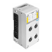
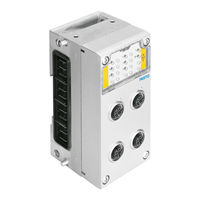
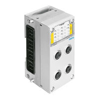
Festo CPX-F8DE-P Input Module Manuals
Manuals and User Guides for Festo CPX-F8DE-P Input Module. We have
6
Festo CPX-F8DE-P Input Module manuals available for free PDF download: Manual, Description, Brief Description, Operating Instructions Manual
Festo CPX-F8DE-P Manual (156 pages)
Input module Terminal CPX
Brand:
Festo
| Category:
Control Unit
| Size: 0 MB
Table of Contents
Table of Contents
5
General Safety Instructions
8
Intended Use
9
Rules for Product Configuration
10
Possible Misuse
12
Achievable Safety Classification
13
Failures Due to a Common Cause (Common Cause Failure - CCF)
15
Requirements for Product Use
15
Transport and Storage Conditions
18
Service
18
Range of Application and Certifications
18
Quoted Guidelines and Standards
20
Product Identification
20
Instructions on this Description
23
Important User Information
24
Product Specific Terms and Abbreviations
26
System Overview CPX-F8DE-P
33
System Overview Cpx-F8De-P
34
CPX Terminal with CPX-F8DE-P
34
Components
34
Required Bus Topology (Control Loop System)
34
Functional Method of the Input Module
34
System Overview CPX-F8DE-P
35
CPX Terminal with CPX-F8DE-P
35
Layout of the Input Module
35
Components
36
Supported Product Versions from CPX
40
Required Bus Topology (Control Loop System)
42
Profisafe
43
Safety Profile Profisafe
43
Process Image (I/O Image)
44
Bit Pattern of the Output and Input Data (F-User Data)
45
Channel-Wise Passivation
47
Functional Method of the Input Module
49
Safe System Status
50
Overview of Applications
50
Details of the Function Modes
52
Use of Switching Signals
71
Channel Bundling
72
Rotary Indexing Table
75
Limit Position Switch
77
Light Curtain
78
Acknowledge Button with Request
79
Two-Wire Sensors
80
Protective Doors on One Channel Pair
80
Protective Door with Two no Switches
81
Profisafe
34
Process Image (I/O Image)
34
Bit Pattern of the Output and Input Data (F-User Data)
34
Installation
84
General Instructions on Installation
85
Module-Related Rules for Configuration
86
Installation
85
Electrical Connection and Display Components
87
Pin Allocation on Connection Block CPX-M-AB-4-M12X2-5POL-T
88
Pin Allocation on Connection Block CPX-M-AB-4-M12X2-5POL
89
Pin Allocation on Connection Block CPX-AB-8-KL-4POL
90
Installation of the Electronic Module
91
Dismantling the Electronics Module
92
Mounting the Electronics Module
92
Set Profisafe Address
93
Connection of Sensors
95
Ensuring the Protection Class
96
Commissioning
98
Commissioning
100
Device Master File (GSDML and GSD)
100
Module Identifiers
100
Preparing for Commissioning
101
Commissioning Steps
102
Set the Profisafe Parameters
103
Interrogation of the CPX Module Parameters
105
Parameter and Signal Display with the Operator Unit CPX-MMI-1
107
Configuration with Siemens STEP 7 (Example)
109
Operation
116
LED Status Display
117
Behaviour During the Start-Up Phase (Startup)
118
Normal Operating Status
118
Operation
117
Diagnostics and Error Handling
122
Diagnostics and Error Handling
123
Overview
123
Error Characteristics
124
Diagnosis Via Leds
126
Behaviour in Response to Original Module Faults
130
Behaviour in Response to Channel Faults
131
Diagnostics Via the Bus Node
133
Diagnostics with the Operator Unit CPX-MMI
133
Service, Repair, Waste Management
136
Repair
137
Service
137
Service, Repair, Waste Management
137
Disposal
138
Technical Appendix
140
Technical Appendix
142
Safety Characteristics
142
Characteristic Values of the Input Module
143
Technical Data of the Connection Blocks
146
Advertisement
Festo CPX-F8DE-P Description (156 pages)
Input module
Brand:
Festo
| Category:
I/O Systems
| Size: 0 MB
Table of Contents
Table of Contents
5
General Safety Instructions
8
Intended Use
9
Rules for Product Configuration
10
Foreseeable Misuse
12
Achievable Safety Rating
13
Failures Due to a Common Cause (Common Cause Failure - CCF)
15
Requirements for Product Use
15
Transport and Storage Conditions
18
Service
18
Range of Application and Approvals
18
Specified Directives and Standards
20
Product Identification
20
Information Regarding this Description
23
Important User Information
24
Product-Specific Terms and Abbreviations
26
System Overview CPX-F8DE-P
33
System Overview Cpx-F8De-P
34
CPX Terminal with CPX-F8DE-P
34
Components
34
Required Bus Topology (Control Chain)
34
Mode of Operation of the Input Module
34
System Overview CPX-F8DE-P
35
CPX Terminal with CPX-F8DE-P
35
Design of the Input Module
35
Components
36
Required Bus Topology (Control Chain)
43
Profisafe
44
Profisafe Safety Profile
44
Process Image (I/O Image)
45
Bit Pattern of the Output and Input Data (F Usage Data)
46
Channel-Wise Passivation
48
Mode of Operation of the Input Module
50
Safe System Status
51
Overview of Applications
51
Details of the Function Modes
53
Profisafe
34
Process Image (I/O Image)
34
Bit Pattern of the Output and Input Data (F Usage Data)
34
Installation
84
General Information about Installation
85
Module-Related Rules for Configuration
86
Installation
85
Electrical Connection and Display Elements
87
Pin Allocation on the Manifold Block CPX-M-AB-4-M12X2-5POL-T
88
Pin Allocation on the Manifold Block CPX-M-AB-4-M12X2-5POL
89
Pin Allocation on the Manifold Block CPX-AB-8-KL-4POL
90
Installation of the Electronics Module
91
Disassembling the Electronics Module
92
Installing the Electronics Module
92
Setting the Profisafe Address
93
Connection of Sensors
95
Ensuring the Degree of Protection
96
Commissioning
98
Commissioning
100
Device Master File (GSDML and GSD)
100
Module Identification
100
Preparing for Commissioning
101
Commissioning Steps
102
Setting the Profisafe Parameters
103
Reading out the CPX Module Parameters
105
Parameter and Signal Display with the Operator Unit CPX-MMI-1
107
Configuration with Siemens STEP 7 (Example)
109
Diagnostics and Error Handling
122
Diagnostics and Error Handling
123
Overview
123
Error Characteristics
124
Diagnostics Using Leds
126
Behaviour in Response to Original Module Errors
130
Behaviour in Response to Channel Errors
131
Diagnostics Via the Bus Node
133
Diagnostics with the Operator Unit CPX-MMI
133
Technical Appendix
140
Technical Appendix
141
Technical Data
141
Safety Characteristics
142
Characteristic Values of the Input Module
143
Technical Data of the Manifold Blocks
146
Festo CPX-F8DE-P Manual (90 pages)
Input module
Brand:
Festo
| Category:
Industrial Equipment
| Size: 3 MB
Table of Contents
Table of Contents
3
Safety
6
Important User Information
6
Danger Categories
6
Marking of Special Information
6
General Safety Instructions
7
Intended Use
7
Rules for Product Configuration
8
Foreseeable Misuse
9
Achievable Safety Classification
9
Failures Due to a Common Cause (Common Cause Failure - CCF)
10
Requirements for Product Use
10
Technical Prerequisites
10
Training of Qualified Personnel
11
Product Conformity
11
UL/CSA Certification
11
Transport and Storage Conditions
11
Service
12
Specified Directives and Standards
12
Product Identification
12
Information Regarding this Description
13
Product-Specific Terms and Abbreviations
13
System Overview CPX-F8DE-P
19
CPX Terminal with CPX-F8DE-P
19
Structure of the Input Module
19
Components
20
Supported CPX Product Versions
23
Required Bus Topology (Control Chain)
24
Profisafe
25
Profisafe Safety Profile
25
Process Image (I/O Image)
26
Bit Pattern of the Output and Input Data (F-User Data)
26
Channel-Based Passivation
28
Mode of Operation of the Input Module
29
Safe System Status
30
Overview of Applications
30
Details of the Function Modes
31
Use of Clock Signals
43
Channel Bundling
44
Application Examples
44
Control Desk
45
Rotary Indexing Table
46
Limit Position Switch
47
Light Curtain
48
Acknowledge Button with Request
49
Two-Wire Sensors
50
Safety Doors on One Channel Pair
50
Safety Door with Two N/O Switches
51
Installation
51
General Information about Installation
51
Module-Related Rules for Configuration
52
Electrical Connection and Display Elements
52
Pin Allocation on the Manifold Block CPC-M-AB-4-M12X2-5POL-T
53
Pin Allocation on the Manifold Block CPX-M-AB-4-M12X2-5POL
54
Pin Allocation on the Manifold Block CPX-AB-8-KL-4POL
55
Installation of the Electronics Module
55
Demounting the Electronics Module
56
Installing the Electronics Module
56
Setting the Profisafe Address
56
Connection of Sensors
58
Ensuring the Degree of Protection
58
Commissioning
59
Compatible Bus Nodes
59
Device Master File (GSDML and GSD)
59
Module Identification
59
Preparing for Commissioning
60
Commissioning Steps
60
Setting the Profisafe Parameters
60
Reading out the CPX Module Parameters
62
Parameter and Signal Display with the Operator Unit CPX-MMI-1
64
Configuration with SIEMENS STEP 7 (Example)
65
Addressing Example
68
Operation
69
LED Status Indication
69
Behaviour During the Start-Up Phase (Start-Up)
70
Normal Operating Status
70
Diagnostics and Error Handling
72
Overview
72
Error Characteristics
72
Diagnostics Using Leds
74
Behaviour in Response to Original Module Errors
78
Behaviour in Response to Channel Errors
80
Diagnostics Via the Bus Node
82
Diagnostics with the Operator Unit CPX-MMI
83
Service, Repair, Disposal
83
Maintenance
83
Repair
83
Disposal
84
Technical Data
84
Approval Information
84
Safety Characteristics
84
Characteristic Values of the Input Module
86
Technical Data of the Manifold Blocks
88
Advertisement
Festo CPX-F8DE-P Brief Description (9 pages)
Brand:
Festo
| Category:
I/O Systems
| Size: 0 MB
Table of Contents
Safety Instructions
1
Achievable Safety Classification
2
Failures Due to a Common Cause (Common Cause Failure – CCF)
2
Requirements for Product Use
2
Training of Qualified Personnel
2
Transport and Storage Conditions
2
Service
2
Range of Application and Approvals
2
Product Identification
2
Connection and Display Components
3
Design of the Input Module
3
Installation
3
Setting the Profisafe Address
3
Dismantling and Mounting
4
Pin Allocation
4
Starting Behaviour of the Input Module
4
Parameter
4
I/O Image
4
Commissioning
5
Safe System Status
5
Function Modes of the Input Module
5
Function Mode 0 – no Signal Evaluation
5
Function Mode 1 – 1Oo1
5
Function Mode 2 – 1Oo1 Test
5
Function Mode 3 – 1Oo1 T (with Clock Signal Monitoring)
5
Function Mode 4 – 1Oo1 D (Antivalent)
6
Function Mode 5 – 1Oo2 (Equivalent)
6
Function Mode 6 – 1Oo2 T (Equivalent, with Clock Signal Monitoring)
6
Function Mode 7 – 1Oo2 D (Two-Hand Control Device en 574 Type IIIC)
6
Function Mode 8 – 1Oo2 T (Equivalent, with Clock Signal Monitoring, Robust)
7
Function Mode 9 – 1 of N (One of N)
7
Function Mode 10 – Coded Identifier
7
Service, Repair, Disposal
7
Technical Data
8
Safety Characteristics
8
Recommended Sensors
8
Electrical Characteristic Values
8
Module Characteristic Values
8
Ambient Characteristics
8
Error Messages
8
Festo CPX-F8DE-P Manual (9 pages)
Input module
Brand:
Festo
| Category:
Control Unit
| Size: 0 MB
Table of Contents
Safety Instructions
1
Product Identification
2
Connection and Display Components
3
Installation
3
Set Profisafe Address
3
Dismounting and Mounting
3
Pin Allocation on the Connection Block
3
Safe System Status
4
Commissioning
4
Starting the Input Module
4
Parameters
4
I/O Image
4
Function Modes of the Input Module
4
Function Mode 0 – no Signal Evaluation
5
Function Mode 1 – 1Oo1
5
Function Mode 2 – 1Oo1 Test (T0, T2, T4, T6 Static Off)
5
Function Mode 3 – 1Oo1 T (with Clock Signal Monitoring)
5
Function Mode 4 – 1Oo1 D (Antivalent)
5
Function Mode 5 – 1Oo2 (Equivalent)
6
Function Mode 6 – 1Oo2 T (Equivalent, with Clock Monitoring)
6
Function Mode 7 – 1Oo2 D (Two-Hand Control Device en 574 Type IIIC)
6
Function Mode 8 – 1Oo2 T (Equivalent, with Clock Monitoring, Robust)
6
Function Mode 9 – 1 of N (One of N)
7
Function Mode 10 – Coded Identifier
7
Service, Repair, Disposal
7
Safety Characteristics
8
Ambient Characteristics
8
Technical Data
8
Festo CPX-F8DE-P Operating Instructions Manual (8 pages)
Input module
Brand:
Festo
| Category:
I/O Systems
| Size: 0 MB
Advertisement
Related Products
Festo CPX-FB32
Festo CPX-FB23
Festo CPX-FB23-24
Festo CPX-FB39
Festo CPX-FB40
Festo CPX-FB14
Festo CPX-FB6
Festo CPX-FVDA-P2
Festo CPX-FVDA-P
Festo CPX-E-EP
Festo Categories
Industrial Equipment
Control Unit
Controller
Touch terminals
DC Drives
More Festo Manuals
Login
Sign In
OR
Sign in with Facebook
Sign in with Google
Upload manual
Upload from disk
Upload from URL