Festo CPX-F8DE-P Manual
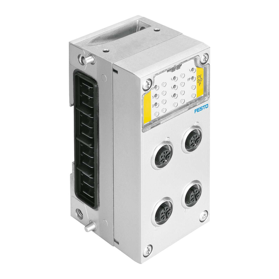
Input module
Hide thumbs
Also See for CPX-F8DE-P:
- Manual (156 pages) ,
- Brief description (9 pages) ,
- Operating instructions manual (8 pages)
Table of Contents
Advertisement
Quick Links
Advertisement
Table of Contents

Related Manuals for Festo CPX-F8DE-P


Summary of Contents for Festo CPX-F8DE-P
- Page 1 CPX-F8DE-P Input module Manual 8035497 8035497 2022-10d [8174432]...
- Page 2 Translation of the original instructions CAGE CLAMP, PI PROFIBUS PROFINET, PROFIsafe, SIEMENS are registered trademarks of the respec- tive trademark owners in certain countries.
-
Page 3: Table Of Contents
CPX terminal with CPX-F8DE-P ........ - Page 4 Behaviour in response to channel errors......80 Festo — CPX-F8DE-P — 2022-10d...
- Page 5 Technical data of the manifold blocks......... 88 Festo — CPX-F8DE-P — 2022-10d...
-
Page 6: Safety
The following pictograms mark passages in the text that contain special information. Pictograms Information: Recommendations, tips and references to other sources of information. Accessories: Information about necessary or useful accessories for the Festo product. ENVIRONMENT Environment: Information about the environmentally friendly use of Festo products. Text symbols and markers 1. -
Page 7: General Safety Instructions
CPX system description CPX-SYS-... Intended use The input module CPX-F8DE-P is intended for reliable recording and evaluation of signals of connected sensors. The input module provides up to eight secure inputs that can be used by a higher-order safety controller in a safety function. -
Page 8: Rules For Product Configuration
Safety Rules for product configuration Operation of the input module CPX-F8DE-P is permissible exclusively in CPX terminals. Operation of the CPX-F8DE-P is permissible only in combination with the following PROFIsafe-compat- ible bus nodes: Bus node from revision Network protocol CPX-FB13... -
Page 9: Foreseeable Misuse
è Tab. 9 Permissible manifold blocks è Tab. 11 Permissible interlinking blocks. NOTICE The use of the input module CPX-F8DE-P for implementation of safety circuits is not permissible in the following cases: • in a CPX terminal equipped with CPX-FEC or CPX-CEC •... -
Page 10: Failures Due To A Common Cause (Common Cause Failure - Ccf)
Only then is operation of the product guaranteed in accordance with the relevant safety regulations. – When connecting standard auxiliary components, also observe the specified limit values for elec- trical connection values and ambient conditions. Festo — CPX-F8DE-P — 2022-10d... -
Page 11: Training Of Qualified Personnel
Work on safety engineering systems may only be carried out by qualified personnel trained in safety engineering. 1.8.3 Product conformity The product-relevant directives are listed in the declaration of conformity è www.festo.com/sp. Product conformity in accordance with EU EMC Directive in accordance with EU Machinery Directive... -
Page 12: Service
– Store and transport the product in its original packaging. The original packaging offers sufficient protection from typical stresses. 1.10 Service Contact your local Festo Service centre in the event of technical problems. 1.11 Specified directives and standards Version EN ISO 13849-1:2015... -
Page 13: Information Regarding This Description
Information regarding this description This description contains general, basic information about how to operate, assemble and install the input module CPX-F8DE-P in conjunction with the CPX terminal and refers exclusively to the following revisions of the input module: This description applies to the following product... - Page 14 Preset safe value that replaces the real process value or the pro- grammed value in the event of a malfunction or when booting safety- related systems. The value 0 is transmitted in the input image with the CPX-F8DE-P (digital inputs). F-Device Collective term for safety-related devices è Safety control unit.
- Page 15 PLe the highest. PROFIBUS Standard for fieldbus communication between controllers (PLC/IPC) and devices in automation technology (PROcess Field BUS) è www.profibus.com PROFINET IO Fieldbus standard based on Industrial Ethernet for communication between controllers (PLC/IPC) and devices è www.profibus.com. Festo — CPX-F8DE-P — 2022-10d...
- Page 16 Function that detects possible cross-circuiting in the circuits connected to the device and that sets a safe mode for the device and/or for the input channel affected. This can be implemented by è cycle monitoring and/or discrepancy monitoring. Festo — CPX-F8DE-P — 2022-10d...
- Page 17 SIL 4 is the highest level of safety integrity. The higher the level, the less probable it is that the system will fail in a dangerous manner. Safety chain All elements of a safety device. Festo — CPX-F8DE-P — 2022-10d...
- Page 18 The procedure is often used with outputs in the form of test pulses and on clocked inputs. Generally speaking, many safety-related signals can be found to have forced switch on/off for detection of short circuits and cross circuits. Tab. 8: Product-specific terms and abbreviations Festo — CPX-F8DE-P — 2022-10d...
-
Page 19: System Overview Cpx-F8De-P
System overview CPX-F8DE-P System overview CPX-F8DE-P CPX terminal with CPX-F8DE-P 2.1.1 Structure of the input module Fig. 1: Design of the input module CPX-F8DE-P Manifold block Interlinking block with busbars, e.g. CPX-M- CPX-M-AB-4-M12X2-5POL(-T) GE-EV Manifold block CPX-AB-8-KL-4POL Product labelling Manifold block CPX-AB-ID-P with internal 8x... -
Page 20: Components
System overview CPX-F8DE-P 2.1.2 Components 2.1.2.1 Manifold blocks The manifold block provides the input module with connection technology. The CPX-F8DE-P may only be operated with the following manifold blocks: Manifold block description CPX-M-AB-4-M12X2-5POL-T M12 metal connection technology – 4 M12 sockets with metal thread, 5-pin –... - Page 21 An interlinking block establishes the mechanical and electrical connection to the CPX terminal. NOTICE Malfunctions possible due to missing shielding. • Use only metal interlinking blocks. Interlinking block description CPX-M-GE-EV without system supply CPX-M-GE-EV-S-7/8-5POL with system supply, connection: 7/8'' (5-pin) Festo — CPX-F8DE-P — 2022-10d...
- Page 22 System overview CPX-F8DE-P Interlinking block description CPX-M-GE-EV-S-7/8-CIP-4P with system supply, connection: 7/8'' (4-pin) CPX-M-GE-EV-S-PP-5POL with system supply, connection: push-pull (5-pin) CPX-M-GE-EV-S-M12-5POL with system supply, connection: M12 (5-pin) CPX-M-GE-EV-Z-7/8-5POL with additional supply, connection: 7/8” (5-pin) Festo — CPX-F8DE-P — 2022-10d...
-
Page 23: Supported Cpx Product Versions
Tab. 11: Permissible interlinking blocks 2.1.3 Supported CPX product versions A PROFIBUS or PROFINET-compatible bus node is required for control of the input module CPX-F8DE-P. The CPX terminal must be fitted with one of the following bus nodes è Product labelling. -
Page 24: Required Bus Topology (Control Chain)
Tab. 14: Supported product versions of the CPX terminal 2.1.4 Required bus topology (control chain) Hardware and software components are required to set up safety-related systems. For example, a safety controller (F-Host) with corresponding planning and programming tools is required. Festo — CPX-F8DE-P — 2022-10d... -
Page 25: Profisafe
The black channel extends from the fieldbus connection on the safety controller to the input module CPX-F8DE-P via the bus node è Fig. 2. The input module processes the PROFIsafe telegrams there. -
Page 26: Process Image (I/O Image)
– parameterisation to V1 mode is rejected. 2.2.2 Process image (I/O image) The safety features of PROFIsafe mean that the input module CPX-F8DE-P occupies 7 bytes for outputs and 6 bytes for inputs in the process image of the CPX terminal. Outputs consist of: –... - Page 27 1 if the related qualification bit is also set to 1. Byte 1 contains the qualification bits. The qualification bits only change to 1 if there is no channel error, and if the channel was depassivated after a previous error in the channel. Festo — CPX-F8DE-P — 2022-10d...
-
Page 28: Channel-Based Passivation
Sequence Channel- Electrical Status in the Qualification Acknowledg- based passi- status at input ment of the vation input image channel error Module is not passi- 1 (active) vated Channel error occurs Festo — CPX-F8DE-P — 2022-10d... -
Page 29: Mode Of Operation Of The Input Module
– overvoltage, undervoltage, overload, short circuit and cross circuit – PROFIsafe communication failure or malfunction – failure or defect of individual safety-determining components of the input module. Festo — CPX-F8DE-P — 2022-10d... -
Page 30: Safe System Status
1oo1 T mechanical 1oo1 D antivalent 1oo2 OSSD 1oo2 T mechanical Sensor with clock signal 1oo1 T OSSD input Emergency stop 1oo1 D antivalent 1oo2 OSSD 1oo2 T mechanical Light curtain 1oo2 OSSD 1oo2 T mechanical Festo — CPX-F8DE-P — 2022-10d... -
Page 31: Details Of The Function Modes
Tab. 19: Possible applications with contact types and appropriate function modes 2.3.3 Details of the function modes The input module CPX-F8DE-P includes various function modes for implementation of safety circuits with recommended sensors. The function modes can be set separately for every channel pair. Recommended sensors... - Page 32 NOTICE The following applies for all applications of sensors and switches in combination with the corre- sponding function modes of the input module CPX-F8DE-P: The achievable safety integrity level, performance level and the category of your system are limited by the component of the safety chain with the lowest characteristic value.
- Page 33 Function mode 2 – 1oo1 test (T0, T2, T4, T6 static off ) Signal evaluation of up to 2 independent single-channel switches/sensors (N/O or N/C) per channel pair. In this function mode, T0, T2, T4 and T6 are not connected to voltage. Festo — CPX-F8DE-P — 2022-10d...
- Page 34 T0, T2, T4, T6 and with common clock signal via T1, T3, T5, T7. This function mode detects short circuits and cross circuits in the sensor wiring. Example A 2 single-channel switches/sensors (N/O or N/C) Festo — CPX-F8DE-P — 2022-10d...
- Page 35 2 single-channel safety sensors with test input Fig. 8: Function mode 3 – 1oo1 T (example B) NOTICE Safety-related evaluation only with the following manifold block: • CPX-AB-8-KL-4POL. 8 single-channel safety sensors can be connected at this manifold block. Festo — CPX-F8DE-P — 2022-10d...
- Page 36 • Ensure that the N/O and/or N/C switches of sensors are connected with the appropriate clock signal connections for the channel pair è circuit diagram. • Note that before every actuation a zero crossover is required (normally closed contact of the N/C switch closed). Festo — CPX-F8DE-P — 2022-10d...
- Page 37 A two-channel sensor (internally equivalent) per channel pair with uniformly unclocked sensor power. In this function mode, T0, T2, T4 and T6 are at static 24 V DC. Fig. 10: Function mode 5 – 1oo2 (example A) Festo — CPX-F8DE-P — 2022-10d...
- Page 38 (example B). 2.3.3.7 Function mode 6 – 1oo2 T (equivalent, with clock signal monitoring) Signal evaluation of a dual-channel switch/sensor (internally equivalent) per channel pair with individ- ually clocked power supply. Festo — CPX-F8DE-P — 2022-10d...
- Page 39 E0, E2, E4, E6. Pressing both pushbuttons within 500 ms generates a logic 1 in the input image of the channel pair. Note that a zero crossing is required before every actuation (both N/C contacts closed). Festo — CPX-F8DE-P — 2022-10d...
- Page 40 Function mode 8 – 1oo2 T (equivalent, with clock signal monitoring, robust) Signal evaluation of mechanical contacts on a two-channel switch/sensor (internally equivalent) or of 2 independent, tried and tested switches. Fig. 14: Function mode 8 – 1oo2T (robust) Festo — CPX-F8DE-P — 2022-10d...
- Page 41 Evaluation of one of max. 8 signals with monitoring of signal change over time, e.g. mode selector switch. The input image is switched 100 ms after actuation. Fig. 15: Function mode 9 – 1 of N (one of N) Festo — CPX-F8DE-P — 2022-10d...
- Page 42 All permitted configurations for setting function mode 9 for multiple channel pairs are listed in the next section. Fig. 16: Function mode 9 for up to 2 circuits – Set the remaining channel pairs as desired – but not to function mode 9. Festo — CPX-F8DE-P — 2022-10d...
-
Page 43: Use Of Clock Signals
Specific clock signals are made available for the relevant input channel via T0, T2, T4 and T6: – to detect cross circuits between inputs and clock signal connections for function modes with clock signals or diagnostics – to detect short circuits between the inputs/clock signal connections and sensor wiring. Festo — CPX-F8DE-P — 2022-10d... -
Page 44: Channel Bundling
The creation of a safety function involves secure evaluation of connected sensors. The following application examples in conjunction with 11 configurable function modes (è 2.3.3 Details of the function modes) show you the different potential options for the intended use of the CPX-F8DE-P. Festo — CPX-F8DE-P — 2022-10d... -
Page 45: Control Desk
Evaluation of the emergency stop button E4/E5 Evaluation of a mode selector switch E6/E7 Tab. 22 NOTICE The safety-related evaluation in this example is only possible with the following manifold blocks: • CPX-M-AB-4-M12X2-5POL-T • CPX-AB-8-KL-4POL. Festo — CPX-F8DE-P — 2022-10d... -
Page 46: Rotary Indexing Table
When connecting the sensors (e.g. SMT-8M-A), the use of pre-assembled Y-cables from the NEBU modular cable system is recommended è www.festo.com/catalogue. è Fig. 19 shows the circuitry of channel pairs with independent sensors. This involves the channel pairs being set with the following function modes:... -
Page 47: Limit Position Switch
Safety-related evaluation only with the following manifold blocks: • CPX-M-AB-4-M12X2-5POL-T • CPX-AB-8-KL-4POL. Antivalence is evaluated in order to diagnose the sensor wiring. Reaching the end position is output as secured logical information in the PAE (input image). Festo — CPX-F8DE-P — 2022-10d... -
Page 48: Light Curtain
The permitted current consumption per connection may vary depending on the manifold block: CPX-M-AB-4-M12X2-5POL up to 2 A CPX-M-AB-4-M12X2-5POL-T up to 0.7 A When wired in a control cabinet, the input module can also be operated with manifold block CPX-AB-8- KL-4POL. All signals are available there without any restriction. Festo — CPX-F8DE-P — 2022-10d... -
Page 49: Acknowledge Button With Request
The safety-related evaluation in this example is only possible on the following manifold blocks: • CPX-M-AB-4-M12X2-5POL-T • CPX-AB-8-KL-4POL. When using manifold block CPX-AB-8-KL-4POL ("CAGE CLAMP“ connection technology), another sensor/switch can be connected to the channel pair via terminals 24 V and E1. Festo — CPX-F8DE-P — 2022-10d... -
Page 50: Two-Wire Sensors
8 electronic two-wire sensors. 2.4.7 2 safety doors on one channel pair This application example shows the circuitry of two safety doors on one channel pair. Fig. 24: 2 safety door sensors on one channel pair Festo — CPX-F8DE-P — 2022-10d... -
Page 51: Safety Door With Two N/O Switches
• Always connect all power circuits for the operating and load voltage supplies U and U EL/SEN Protection from electric shock (protection from direct and indirect contact) in accordance with IEC 60204-1 (Electrical equipment of machines, General requirements) is guaranteed with the use of PELV circuits. Festo — CPX-F8DE-P — 2022-10d... -
Page 52: Module-Related Rules For Configuration
Installation 3.1.1 Module-related rules for configuration – Plug input module CPX-F8DE-P into one of the following interlinking blocks only: – CPX-M-GE-EV – CPX-M-GE-EV-S-7/8-5POL – CPX-M-GE-EV-S-7/8-CIP-4P – CPX-M-GE-EV-S-PP-5POL – CPX-M-GE-EV-S-M12-5POL – CPX-M-GE-EV-Z-7/8-5POL – CPX-M-GE-EV-Z-PP-5POL – CPX-M-GE-EV-W-M12-5POL. – Only operate input module with one of the following manifold blocks: –... -
Page 53: Pin Allocation On The Manifold Block Cpc-M-Ab-4-M12X2-5Pol-T
Installation Detailed information about the LED è 6.3 Diagnostics using LEDs 3.2.1 Pin allocation on the manifold block CPC-M-AB-4-M12X2-5POL-T Fig. 27: Pin allocation with M12 manifold block CPX-M-AB-4-M12X2-5POL-T Festo — CPX-F8DE-P — 2022-10d... -
Page 54: Pin Allocation On The Manifold Block Cpx-M-Ab-4-M12X2-5Pol
Installation 3.2.2 Pin allocation on the manifold block CPX-M-AB-4-M12X2-5POL Fig. 28: Pin allocation with M12 manifold block CPX-M-AB-4-M12X2-5POL The metal thread of the manifold block CPX-M-AB-4-M12X2-5POL is internally connected to pin 5 (functional earth FE). Festo — CPX-F8DE-P — 2022-10d... -
Page 55: Pin Allocation On The Manifold Block Cpx-Ab-8-Kl-4Pol
• Never pull/push the electronics module from/into the interlinking block when the power is switched Electronics modules include electrostatically sensitive devices. • Observe the handling specifications for electrostatically sensitive devices. • Discharge static electricity from your body before assembling or disassembling modules to protect the modules. Festo — CPX-F8DE-P — 2022-10d... -
Page 56: Demounting The Electronics Module
10x DIL switch. Both settings must match. Valid PROFIsafe addresses: 1 … 1022 The 10-way DIL switch is located directly on the electronics module and can be set while the manifold block is not mounted . Festo — CPX-F8DE-P — 2022-10d... - Page 57 2. Remove manifold block è 3.3.1 Demounting the electronics module. 3. Set PROFIsafe address with the binary coded 10x DIL switch è Fig. 30. Valid PROFIsafe addresses: 1 … 1022 4. Replace the manifold block è 3.3.2 Installing the electronics module. Festo — CPX-F8DE-P — 2022-10d...
-
Page 58: Connection Of Sensors
Technical data of the manifold blocks) and on the plug connectors, cover caps and coverings. – Use connection hardware with the required degree of protection. – Use cover caps to seal unused M12 connections. – Close the terminal strip of the manifold block CPX-AB-8-KL-4POL with cover AK-8KL. Accessories è www.festo.com/catalogue Festo — CPX-F8DE-P — 2022-10d... -
Page 59: Commissioning
The configuration depends on the control system. The basic approach and required configuration data are presented in the following pages. Device master file (GSDML and GSD) Along with the input module CPX-F8DE-P, you will need a current GSDML/GSD device master file for configuration and programming. Reference source Current versions of the GSDML/GSD files for CPX terminals can be found on the Festo websites è www.festo.com/sp. -
Page 60: Preparing For Commissioning
1) Module identifier in operator unit 2) 4 bytes each are used exclusively for PROFIsafe communications Tab. 26: Module identifier of the input module CPX-F8DE-P Preparing for commissioning 1. Ensure that the CPX terminal is mounted correctly è CPX system description. - Page 61 Commissioning PROFIsafe General description The following applies for Value parameters CPX-F8DE-P: – CPX-F8DE-P does not pro- – No check F_Check_iPar Determines whether the indi- vidual device parameters vide individual device (cannot be (CPX module parameters) are parameters. changed) to be taken into account...
-
Page 62: Reading Out The Cpx Module Parameters
The cycle time for calling the safety program must be shorter than the watchdog time set here. – CPX-F8DE-P does not pro- – 0 F_iPar_CRC CRC via the individual device parameters (i-parameters). vide individual device (cannot be parameters. - Page 63 Position of the 10x DIL switch for the PROFIsafe address of the module, bits 8 and 9 1) Parameters read-only via operator unit and command interpreter (CI). Tab. 28: Overview – module parameters CPX-F8DE-P Module parameter: DIL switch setting Operator unit Func- 4828 + m * 64 +22 m = module number (0 … 47)
-
Page 64: Parameter And Signal Display With The Operator Unit Cpx-Mmi-1
The header of the operator unit displays the short text [F8DI-P]. An example is shown in the diagram below: Fig. 31: Module identifier of the input module CPX-F8DE-P on the operator unit The following image shows the specific views for the input module CPX-F8DE-P as an example. Festo — CPX-F8DE-P — 2022-10d... -
Page 65: Configuration With Siemens Step 7 (Example)
Commissioning Fig. 32: Specific views for CPX-F8DE-P on the operator unit When calling up the command [Monitoring (M)], the logical states of the 8 input channels and the related qualification bits (Qualifiers) are displayed in accordance with the set function modes. The display of input signals and qualification bits corresponds here to the PROFIsafe process image. - Page 66 Commissioning 3. In the configuration table double-click the row of the input module CPX-F8DE-P. Ä The "Properties – F8DE-P" dialogue box is displayed. 4. Addresses tab: set the required starting addresses for inputs and outputs. 5. Parameters tab: set default parameters on the input module.
- Page 67 PROFIsafe address set on the input module with the DIL switch è Fur- ther information. You have access to the PROFIsafe parameter of the input module in this tab. You can find detailed information about the individual parameters in è 4.6 Setting the PROFIsafe parameters. Festo — CPX-F8DE-P — 2022-10d...
-
Page 68: Addressing Example
I address O address Bus node CPX-FB13 Digital 8x input module with single-channel diagnostics CPX-8DI-D Safety input module 1 ... 6 1 ... 7 CPX-F8DE-P Safety output module 9 ... 14 9 ... 14 CPX-FVDA-P2 Festo — CPX-F8DE-P — 2022-10d... -
Page 69: Operation
The designations of the LEDs correspond to the physical contacts E0 to E7. • Note the special position of the input signals in the input image of the CPX-F8DE-P è 2.2.3 Bit pattern of the output and input data (F-user data). -
Page 70: Behaviour During The Start-Up Phase (Start-Up)
LED image Like sensor PROFIsafe communication in pro- signal gress. Like sensor PROFIsafe communication in pro- signal gress. Channel error detected at input. PROFIsafe communication in pro- gress. Operator Acknowledge Requested LED flashes quickly Festo — CPX-F8DE-P — 2022-10d... - Page 71 PROFIsafe parameters not avail- able. Self-test error LED flashes quickly 1) Refers to the input channel to which the relevant status LED is assigned. 2) Input image based on calculation of operating mode. Tab. 32: Normal operating status Festo — CPX-F8DE-P — 2022-10d...
-
Page 72: Diagnostics And Error Handling
I/O diagnostics CPX-F8DE-P reports specific malfunctions to è Tab. 34 Error mes- interface the CPX bus node as error numbers. The I/O sages diagnostic interface enables the data to be è CPX system queried. - Page 73 Module error overtemperature ✓ ✓ ✓ ✓ ✓ ✓ ✓ ✓ ✓ ✓ ✓ Channel error channel function ✓ ✓ ✓ ✓ ✓ ✓ ✓ ✓ ✓ ✓ ✓ Module error in self-test Tab. 34: Error messages Festo — CPX-F8DE-P — 2022-10d...
-
Page 74: Diagnostics Using Leds
Diagnostics using LEDs The following LEDs for on-site diagnostics are located under the transparent covering of the module: Fig. 35: LED display of the input module CPX-F8DE-P NOTICE The LED display of the input module is not designed for safety purposes. - Page 75 – Overtemperature LED on – Absence of safety parameterisa- tion – Defective safety communication – Channel error during "module- based passivation" configuration 1) If self-test errors reoccur: replace input module. Tab. 35: Module error LED Festo — CPX-F8DE-P — 2022-10d...
- Page 76 A signal is not A signal is not pending at the A signal is not pending at the pending at the input. input. input. The ambivalent or a foreign LED is clock signal is present at the input. Festo — CPX-F8DE-P — 2022-10d...
- Page 77 – Communication timeout terisation. – Parameter error – Safety parameterisation invalid LED flashes – PROFIsafe communication cannot slowly be established. – Operator acknowledge possible – No module errors are pending, reintegration is possible. LED flashes quickly Festo — CPX-F8DE-P — 2022-10d...
-
Page 78: Behaviour In Response To Original Module Errors
è 3.4 Setting the PRO- (F_Dest_Add) FIsafe address and è 4.8 Configuration with SIEMENS STEP 7 (example). – Transmit new parame- ters. – Remedy source of mal- Error in safe communica- tion function. Festo — CPX-F8DE-P — 2022-10d... - Page 79 – Replace input module. test Tab. 39: Behaviour in response to module errors All input channels on the input module are passivated in response to module errors. – After remedial action: reintegrate the input module. Festo — CPX-F8DE-P — 2022-10d...
-
Page 80: Behaviour In Response To Channel Errors
– Check N/C contact of present before release of safety function sensor. – FE connected to T1, T3, – Request antivalent T5 or T7 sensor signal. flashes 1x briefly – Error in the parameteri- – Set permitted mode. sation Festo — CPX-F8DE-P — 2022-10d... - Page 81 – multiple clock signals at – Check wiring of clock input signals. – Clock signals swapped flashes 2x briefly – Internal monitoring has – Check sensors for faulty detected unexpected signals. malfunctions on the affected input channel flashes quickly Festo — CPX-F8DE-P — 2022-10d...
-
Page 82: Diagnostics Via The Bus Node
Tab. 40: Behaviour in response to channel errors – After remedial action: always reintegrate the input module. Diagnostics via the bus node Information on diagnostics of the bus node can be found in the description of the corresponding bus node. Festo — CPX-F8DE-P — 2022-10d... -
Page 83: Diagnostics With The Operator Unit Cpx-Mmi
The operator unit displays current error messages from the input module in plain text. Fig. 36: Module identifier of the input module CPX-F8DE-P on the operator unit Furthermore, the operator unit offers access to the diagnostic memory è Description of CPX-MMI-1... -
Page 84: Disposal
TÜV Rheinland UK Ltd, UK Approved Body No. 2571 Certificate no. 01/205U/5444.00/22 Tab. 41: Approval information Safety characteristics Safety characteristics Function mode Safety classification CPX-F8DE-P – in accordance with PL d, up to PL e, Cat. 4 EN ISO 13849-1 Cat. 2 Festo — CPX-F8DE-P — 2022-10d... - Page 85 [years] > 2500 MTTF Mean Time To dangerous Failure (Mean time to dangerous failure) [1/h] 1.0 x 10 –9 Probability of dangerous Failure per Hour (probability of dangerous failure per hour) Hardware Fault Tolerance (Hardware Fault Tolerance) Festo — CPX-F8DE-P — 2022-10d...
-
Page 86: Characteristic Values Of The Input Module
Input characteristics in accordance with Type 2 IEC 61131-2 for digital inputs Max. accepted test pulse duration at the [ms] input Max. load current per clock line T0, T2, T4, T6 [A] Max. total current at T1, T3, T5, T7 Festo — CPX-F8DE-P — 2022-10d... - Page 87 PNP (positive switching) Compatible with fast start- up (FSU) < 2 Time for switch-on phase until input module is ready (start-up) Max. tolerance time until diagnostic message of channel fault Tab. 45: Module characteristic values Festo — CPX-F8DE-P — 2022-10d...
-
Page 88: Technical Data Of The Manifold Blocks
1) Degree of protection is achieved with the permitted combination with interlinking block and connectors. Tab. 47: Technical data CPX-M-AB-4-M12X2-5POL-T CPX-M-AB-4-M12X2-5POL Degree of protection in accordance IP65, completely mounted, plug inserted or provided with with EN 60 529 cover cap ISK-M12 Information on materials: housing Die-cast aluminium Festo — CPX-F8DE-P — 2022-10d... - Page 89 Degree of protection in accordance IP65, completely installed with EN 60 529 Information on materials: housing polyamide-reinforced, polycarbonate 1) Degree of protection is achieved with the permitted combination with interlinking block. Tab. 50: Technical data CPX-AB-ID-P Festo — CPX-F8DE-P — 2022-10d...
- Page 90 Copyright: Festo AG & Co. KG Ruiter Straße 82 73734 Esslingen Germany Phone: +49 711 347-0 +49 711 347-2144 service_international@festo.com © 2022 all rights reserved to Festo SE & Co. KG Internet: www.festo.com...
Need help?
Do you have a question about the CPX-F8DE-P and is the answer not in the manual?
Questions and answers