
Related Manuals for Emerson Daniel Series


Summary of Contents for Emerson Daniel Series
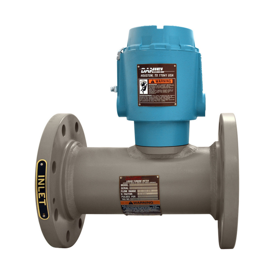
- Page 1 User manual P/N 3-9008-507, Rev AF September 2020 ™ Daniel Series 1500 Liquid Turbine Meter NPS 1 through 2.5...
- Page 2 Emerson employees. Emerson will not accept your returned equipment if you fail to follow Emerson procedures. Return procedures and forms are available on our web support site at www.emerson.com, or by phoning the Emerson Customer Service department.
-
Page 3: Table Of Contents
User manual Contents P/N 3-9008-507 September 2020 Contents Part I Plan Chapter 1 Introduction......................7 1.1 Purpose of this manual........................ 7 1.2 Hazard messages......................... 7 1.3 Personnel qualifications....................... 7 1.4 Warranty restrictions........................9 1.5 Assistance............................9 1.6 Description of the Series 1500 Liquid Turbine Meter (LTM)............10 1.7 Agency certifications for the Series 1500 LTM................ - Page 4 Chapter 11 Spare parts......................101 11.1 Recommended spare parts....................101 Chapter 12 Decommission the turbine meter................103 12.1 Shut down the turbine meter....................103 12.2 Turbine meter disassembly/assembly..................103 12.3 Shipment of the meter......................104 Daniel Series 1500 Liquid Turbine Meter, NPS 1-2.5...
-
Page 5: Part I Plan
User manual Plan P/N 3-9008-507 September 2020 Part I Plan User manual... - Page 6 Plan User manual September 2020 P/N 3-9008-507 Daniel Series 1500 Liquid Turbine Meter, NPS 1-2.5...
-
Page 7: Chapter 1 Introduction
September 2020 Introduction Purpose of this manual Emerson Daniel designed this manual to guide owners and personnel in the installation, operation and maintenance of the Daniel Series 1500 Liquid Turbine Meter Manual, 3-9008-507. It is imperative that product owners and operation personnel read and follow the information contained in this manual to ensure that the turbine meter is installed correctly and is operating according to the design, certifications and safety considerations. - Page 8 Operation of this product on pressurized lines may potentially imply operational risk for personnel and equipment from the potential escape of hot gas or liquid, which could result in serious injury. Observe all precautionary signs on the equipment. Daniel Series 1500 Liquid Turbine Meter, NPS 1-2.5...
-
Page 9: Warranty Restrictions
Emerson assumes no responsibility for incidents, or consequences of incidents, occurring as a result of the use of this product by others than Emerson or its designated personnel, and have no liability whatsoever for any such work. -
Page 10: Description Of The Series 1500 Liquid Turbine Meter (Ltm)
1.6.1 General features of the turbine meter The Daniel Series 1500 Liquid Turbine Meter (LTM) is a volumetric flow metering and transmitting device used for accurate measurement of hydrocarbons and other related process fluids. The design allows high operational flow rates, extended flow ranges and sustained performance capability. - Page 11 • All Daniel Series 1500 Liquid Turbine Meters have, as standard, the LME which is fitted with two pickoffs and a dual channel preamplifier. •...
- Page 12 Introduction User manual September 2020 P/N 3-9008-507 Configurations for LME assembly - Standard enclosure, LME assembly - High temperature RME assembly - Pipe mount RME assembly - Wall mount are shown below. Daniel Series 1500 Liquid Turbine Meter, NPS 1-2.5...
- Page 13 User manual Introduction P/N 3-9008-507 September 2020 LME assembly - Standard enclosure Figure 1-1: Part identification for a standard enclosure User manual...
- Page 14 LME housing and Sensor housing is a spigot joint with a minimum axial length of 26.16 mm (1.030 in), radial length of 3.18 mm (0.125 in), and a clearance of 0.07 mm (0.0028 in). Daniel Series 1500 Liquid Turbine Meter, NPS 1-2.5...
- Page 15 User manual Introduction P/N 3-9008-507 September 2020 LME assembly - Internal Totalizer Figure 1-2: Part identification for the LME with Internal Totalizer User manual...
- Page 16 The joint between the LME cover and housing is a threaded joint. The joint between the LME housing and sensor housing is a cylindrical joint which has an axial length of 25.4 mm (1 in) and a clearance of 0.038 mm (0.0015 in). Daniel Series 1500 Liquid Turbine Meter, NPS 1-2.5...
- Page 17 User manual Introduction P/N 3-9008-507 September 2020 LME assembly - with Two Preamps Figure 1-3: Part identification Two preamps configuration User manual...
- Page 18 The joint between the LME cover and housing is a threaded joint. The joint between the LME housing and sensor housing is a cylindrical joint which has an axial length of 25.4 mm (1 in) and a clearance of 0.038 mm (0.0015 in). Daniel Series 1500 Liquid Turbine Meter, NPS 1-2.5...
- Page 19 User manual Introduction P/N 3-9008-507 September 2020 LME assembly - High temperature Figure 1-4: Part identification for a high temperature enclosure User manual...
- Page 20 LME housing and Sensor housing is a spigot joint with a minimum axial length of 26.16 mm (1.030 in), radial length of 3.18 mm (0.125 in), and a clearance of 0.07 mm (0.0028 in). Daniel Series 1500 Liquid Turbine Meter, NPS 1-2.5...
- Page 21 User manual Introduction P/N 3-9008-507 September 2020 RME assembly - Pipe mount Figure 1-5: Part identification for an RME assembly - Pipe mount User manual...
- Page 22 RME housing and Sensor housing is a spigot joint with a minimum axial length of 26.16 mm (1.030 in), radial length of 3.18 mm (0.125 in), and a clearance of 0.07 mm (0.0028 in). Daniel Series 1500 Liquid Turbine Meter, NPS 1-2.5...
- Page 23 User manual Introduction P/N 3-9008-507 September 2020 RME assembly - Wall mount Figure 1-6: Part identification for an RME assembly - Wall mount User manual...
- Page 24 RME housing and Sensor housing is a spigot joint with a minimum axial length of 26.16 mm (1.030 in), radial length of 3.18 mm (0.125 in), and a clearance of 0.07 mm (0.0028 in). Daniel Series 1500 Liquid Turbine Meter, NPS 1-2.5...
- Page 25 User manual Introduction P/N 3-9008-507 September 2020 Meter housing internal components - NPS 1 The information below identifies and describes the NPS 1 meter housing components. Figure 1-7: Part identification for an NPS 1 LTM User manual...
- Page 26 Emerson Flow sales representative. For a bidirectional assembly, item number 56 will be replaced with item number 52. Note For alternative materials and NACE, contact Emerson Flow sales and service. Daniel Series 1500 Liquid Turbine Meter, NPS 1-2.5...
- Page 27 User manual Introduction P/N 3-9008-507 September 2020 Meter housing internal components - NPS 1.5 The information below identifies and describes the NPS 1.5 meter housing components. Figure 1-8: Part identification for a NPS 1.5 LTM User manual...
- Page 28 Emerson Flow sales representative. For a bidirectional assembly, item number 57 will be replaced with item number 52. Note For alternative materials and NACE, contact Emerson Flow sales and service. Daniel Series 1500 Liquid Turbine Meter, NPS 1-2.5...
- Page 29 User manual Introduction P/N 3-9008-507 September 2020 Meter housing internal components - NPS 2 and 2.5 The information below identifies and describes the 2 and 2.5 meter housing components. Figure 1-9: Part identification for a NPS 2 and 2.5 LTM User manual...
- Page 30 The meter housing shown is for class 150 raised face flange. For additional classes and flange types contact Emerson Flow sales representative. Note For alternative materials and NACE, contact Emerson Flow sales and service. Daniel Series 1500 Liquid Turbine Meter, NPS 1-2.5...
-
Page 31: Agency Certifications For The Series 1500 Ltm
User manual Introduction P/N 3-9008-507 September 2020 Agency certifications for the Series 1500 LTM Table 1-11: Agency certifications for the Series 1500 LTM Certification type Description Certificate Electrical UL and CUL: Class I, Div. 1, Groups IECEx UL 11.0031X Rev. 7 B, C &... - Page 32 Introduction User manual September 2020 P/N 3-9008-507 Daniel Series 1500 Liquid Turbine Meter, NPS 1-2.5...
-
Page 33: Operating Conditions And Specifications
-40 ºC to 204 ºC (-40 ºF to 400 ºF) (Stainless steel flanges) Fluid static pressure The maximum working pressure for the Daniel Series 1500 Liquid Turbine Meter is based on the temperature/ pressure rating of the ANSI B16.5 flanges. For maximum working pressures at intermediate temperatures refer to ANSI B16.5. - Page 34 Corrosive service Select the material compatible with specific processes and atmospheric environments. Implement a periodic inspection and maintenance program to ensure that pressure-retaining components are free from corrosion and erosion. Daniel Series 1500 Liquid Turbine Meter, NPS 1-2.5...
- Page 35 User manual Operating conditions and specifications P/N 3-9008-507 September 2020 Table 2-2: Environmental conditions (continued) Parameter type Description Low and freezing temperatures Low specific gravities or high viscosities reduce the flow range of the turbine meter. Refer to Operating parameters for the LTM for more information.
- Page 36 Insufficient back pressure leads to measurement inaccuracy. The resulting flashing and cavitation is extremely damaging to the flow meter and pipe work. Figure 2-1: Effects of back pressure Daniel Series 1500 Liquid Turbine Meter, NPS 1-2.5...
- Page 37 User manual Operating conditions and specifications P/N 3-9008-507 September 2020 Back pressure calculation ≥ 2Δp + 1.25p Equation 2-2: Back pressure calculation = Minimum back pressure, pounds per square inch gauge (psig) Δp = Pressure drop through the meter at the maximum operating flow rate for the liquid being measured, pounds per square inch (psi).
-
Page 38: Specifications For The Ltm
Variable voltage output: • Type: Square wave • Frequency range: 0 to 5 kHz • Amplitude: 0 to Supply voltage • 1000 Ohm internal pull-ups, 70 mA, max. Construction Delrin housing Solid epoxy encapsulation Daniel Series 1500 Liquid Turbine Meter, NPS 1-2.5... - Page 39 User manual Operating conditions and specifications P/N 3-9008-507 September 2020 Table 2-4: 2415 Intrinsically safe preamplifier performance Parameter type Description Inputs Supply voltage: 13-25 Vdc @ ≤12 mA Sensor type: Reluctance Signal: Sine wave Preamplifier sensitivity: • 60 mVpp • 10Hz - 1KHz (60mVpp) •...
- Page 40 +10 to 30 Vdc Common Common Channel A output Channel B output TTL out A TTL out B TB2 - Channel A pickoff (1) White TB3 - Channel B pickoff (1) White Daniel Series 1500 Liquid Turbine Meter, NPS 1-2.5...
- Page 41 User manual Operating conditions and specifications P/N 3-9008-507 September 2020 Table 2-8: 2415 Intrinsically safe preamplifier configuration Designator Terminal connections Description Customer connection Supply voltage Common Output signal (half frequency) Output signal Pickoff (1) White Table 2-9: 1815B Zero crossing preamplifier configuration Designator Terminal connections Description...
- Page 42 It is important that the correct service manual be referenced before attempting to use accessories or instrumentation with the Series 1500 LTM. Contact the factory or nearest Emerson service office if service manuals for were not received at the time of purchase or delivery.
- Page 43 User manual Operating conditions and specifications P/N 3-9008-507 September 2020 2.2.2 Requirements and limitations for installation Figure 2-2: Typical installation for a Series 1500 LTM • Note the direction of flow indicated on the plate near the inlet flange and install accordingly.
- Page 44 269.1 228.6 114.3 269.1 254.0 127.0 280.2 Table 2-12: Flow meter and flow straightening section dimensions for the Series 1500 LTM NPS 1-2.5 Size Inches Inches Inches 838.2 1181.1 990.6 12.5 1206.5 Daniel Series 1500 Liquid Turbine Meter, NPS 1-2.5...
- Page 45 User manual Operating conditions and specifications P/N 3-9008-507 September 2020 Table 2-13: Weight table for the stainless steel LME Size ANSI class 150 ANSI class 300 ANSI class 600 10.6 11.6 12.6 14.1 15.6 13.6 14.6 16.6 17.6 20.6 22.6 User manual...
- Page 46 Operating conditions and specifications User manual September 2020 P/N 3-9008-507 Daniel Series 1500 Liquid Turbine Meter, NPS 1-2.5...
-
Page 47: Turbine Meter Handling
User manual Turbine meter handling P/N 3-9008-507 September 2020 Turbine meter handling Receive the turbine meter WARNING EQUIPMENT HANDLING AND OPERATING HAZARD Wear personal protective equipment appropriate to the situation when working with the turbine meter. Adhere to all safety standards and best practices for operating the equipment. - Page 48 Do not remove nameplates or labels. Doing so will void the turbine meter warranty. Stacking When stacking equipment, follow all safety standards, taking into account the type of box used, the maximum height of the equipment, the maximum number of boxes stacked, etc. Daniel Series 1500 Liquid Turbine Meter, NPS 1-2.5...
-
Page 49: Prepare The Turbine Meter For Use
User manual Prepare the turbine meter for use P/N 3-9008-507 September 2020 Prepare the turbine meter for use Lifting conditions WARNING CRUSHING HAZARD During turbine meter installation or removal, always place the unit on a stable platform or surface that supports its assembled weight. Failure to comply could allow the turbine meter to roll, resulting in death, serious injury or equipment damage. -
Page 50: Lifting Requirements For Personnel
Minimum clearances for installation, operation and maintenance for the assemble weight. The following instructions provide general guidelines using lifting slings only on the Daniel turbine meter. Use appropriately rated lifting slings when lifting the turbine meter. Daniel Series 1500 Liquid Turbine Meter, NPS 1-2.5... - Page 51 Prepare the turbine meter for use P/N 3-9008-507 September 2020 Safety precautions using appropriately rated lifting slings When lifting a liquid turbine meter by itself, Emerson recommends using lifting slings appropriately positioned at designated areas of the turbine meter. WARNING LIFTING HAZARD...
- Page 52 Doing this may cause injury and/or damage the equipment. • Never apply shock loads to the turbine meter. Always lift the turbine meter gradually. If shock loading occurs, inspect the slings per manufacturer's recommendations prior to further use. Daniel Series 1500 Liquid Turbine Meter, NPS 1-2.5...
-
Page 53: Configuration Of The Turbine Meter
Prepare the turbine meter for use P/N 3-9008-507 September 2020 Configuration of the turbine meter The Emerson factory configures the turbine meter internal components. Inspect the internal components before installation. 4.3.1 Orientation and position of the turbine meter Flow direction Turbine meters can be used for uni-directional or bi-directional flows. - Page 54 Comply with local government regulations and company requirements. Important Ensure that piping or other attachments connected to the turbine meter are not under stress. Important Provide fire prevention measures and equipment per local regulations. Daniel Series 1500 Liquid Turbine Meter, NPS 1-2.5...
- Page 55 User manual Prepare the turbine meter for use P/N 3-9008-507 September 2020 4.3.3 Calibration options for the turbine meter Daniel offers a standard six-point calibration (from 10% to 100%); or can provide other customer requested calibration data. Table 4-2: Standard calibration for a Daniel Liquid Turbine Meter Calibration type Description Linearity...
- Page 56 LME as the primary ground. A secondary ground is located outside of the LME. Refer to Figure 4-4 Figure 4-5. Digital grounds should never be connected to chassis ground. Daniel Series 1500 Liquid Turbine Meter, NPS 1-2.5...
- Page 57 User manual Prepare the turbine meter for use P/N 3-9008-507 September 2020 Figure 4-4: External ground lug A. External ground lug Figure 4-5: Internal ground lug A. Internal ground lug Important Use the internal grounding terminal as the primary equipment ground. The external terminal is only a supplemental bonding connection where local authorities permit or require such a connection.
- Page 58 Table 4-4. Table 4-4: Installation dimensions for the RME Device Transmission distance Pickoff to RME 6.1 meters (20 ft.) maximum from RME dual channel Preamplifier to receiver 1525 meters (5,000 ft.) maximum Daniel Series 1500 Liquid Turbine Meter, NPS 1-2.5...
- Page 59 User manual Prepare the turbine meter for use P/N 3-9008-507 September 2020 Figure 4-6: Typical installation for the RME 4.3.8 Install the security seal Security seals protect the integrity of the turbine meter metrology and prevent preamplifier and pickoff tampering. Follow the steps below to seal the electronics enclosure of the Daniel 1500 LTM after commissioning.
- Page 60 (maximum wire diameter 2.0 mm, .078 inch). 3. Adjust the security wire, removing all slack and thread into the lead seal. 4. Cut the ends of the wire to remove any excess wire. Daniel Series 1500 Liquid Turbine Meter, NPS 1-2.5...
-
Page 61: Part Ii Install
User manual Install P/N 3-9008-507 September 2020 Part II Install User manual... - Page 62 Install User manual September 2020 P/N 3-9008-507 Daniel Series 1500 Liquid Turbine Meter, NPS 1-2.5...
-
Page 63: Chapter 5 Installation Prerequisites
User manual Installation prerequisites P/N 3-9008-507 September 2020 Installation prerequisites Pre-start checks Procedure 1. Inspect all electrical connections to ensure compliance to electrical codes and safety regulations. 2. Inspect all bolts used to secure the turbine meter in line to ensure that correct mounting procedures have been followed and that flange connections are leak- free. - Page 64 Installation prerequisites User manual September 2020 P/N 3-9008-507 Daniel Series 1500 Liquid Turbine Meter, NPS 1-2.5...
-
Page 65: Chapter 6 Installation Procedure
User manual Installation procedure P/N 3-9008-507 September 2020 Installation procedure Cathodic protection Table 6-1: Standards for cathodic protection Material Daniel standard cathodic protection Carbon steel Zinc Phosphate Consult the factory for other protection. Mechanical components assembly Install the meter housing (e.g., flanges) onto the pipeline. The meter housing internal components are assembled by the factory. -
Page 66: Assemble The Electronic Components
Failure to comply may result in death or serious injury. Procedure 1. Remove the security seal wire. 2. Remove the security latch using the 3 mm Allen key. Daniel Series 1500 Liquid Turbine Meter, NPS 1-2.5... - Page 67 5. Install the electronics according to Wiring and cable connections. Consult with Emerson if the preamplifier acquired is other than a dual channel preamplifier. WARNING SHOCK AND EXPLOSION HAZARD Verify that the LME and/or RME is grounded.
- Page 68 Installation procedure User manual September 2020 P/N 3-9008-507 Daniel Series 1500 Liquid Turbine Meter, NPS 1-2.5...
-
Page 69: Chapter 7 Testing
User manual Testing P/N 3-9008-507 September 2020 Testing Test the turbine meter 7.1.1 Commission the turbine meter After installation, commission the turbine meter to ensure that the equipment is working properly. Procedure 1. Inspect all electrical connections to ensure compliance with electrical codes and safety regulations. - Page 70 Testing User manual September 2020 P/N 3-9008-507 Daniel Series 1500 Liquid Turbine Meter, NPS 1-2.5...
- Page 71 User manual Operate P/N 3-9008-507 September 2020 Part III Operate User manual...
- Page 72 Operate User manual September 2020 P/N 3-9008-507 Daniel Series 1500 Liquid Turbine Meter, NPS 1-2.5...
-
Page 73: Chapter 8 Operation Parameters
Operation parameters Operation overview The Daniel Series 1500 LTM is a volumetric flow measuring and transmitting device that produces an output signal proportional to the rate-of-flow of the liquid being measured. The primary output is a single or dual high resolution signal that is amplified and shaped by an integral preamplifier mounted within an explosion-proof housing. - Page 74 This wave pulse can be fed directly to remote totalizing counters, digital readout devices, presets, or control instrumentation. NOTICE Inspect all electrical connections to ensure compliance to electrical codes and safety regulations. Daniel Series 1500 Liquid Turbine Meter, NPS 1-2.5...
-
Page 75: Part Iv Maintain
User manual Maintain P/N 3-9008-507 September 2020 Part IV Maintain User manual... - Page 76 Maintain User manual September 2020 P/N 3-9008-507 Daniel Series 1500 Liquid Turbine Meter, NPS 1-2.5...
-
Page 77: Chapter 9 Planned Maintenance
User manual Planned maintenance P/N 3-9008-507 September 2020 Planned maintenance Maintenance considerations Read and understand all instructions and operating procedures before performing maintenance procedure, internal component inspections or field requirement changes. To ensure safe and accurate performance, only informed and trained personnel should install, operate, repair and maintain this product. -
Page 78: Prepare For Mechanical Disassembly
6. Disconnect conduit connections to the turbine meter. 7. Remove turbine meter from line. Refer to Lifting equipment Lifting conditions, Lifting requirements for personnel, and Safety precautions using appropriately rated lifting slings for instructions on lifting the turbine meter. Daniel Series 1500 Liquid Turbine Meter, NPS 1-2.5... - Page 79 User manual Planned maintenance P/N 3-9008-507 September 2020 9.3.1 Disassemble internal meter housing components - NPS Procedure 1. Remove the retainer ring from the upstream end of the meter. Figure 9-1: Retainer ring removal Note The NPS 1 meter has one inlet retainer ring instead of a hex nut as the NPS 1.5, 2 and 2.5.
- Page 80 Thrust washers may remain in the cones but may be loose. Be careful not to drop the thrust washer. 4. Remove the rotor from the shaft. The journal may come off with the rotor or remain on the shaft. Take care not to drop the journal. Daniel Series 1500 Liquid Turbine Meter, NPS 1-2.5...
- Page 81 User manual Planned maintenance P/N 3-9008-507 September 2020 Figure 9-4: Rotor removal A. Downstream cone Note The letter "A" is etched on one side of rotor hub. The letter "B" is located on the other side. Notice which direction the rotor was assembled. 5.
- Page 82 NPS 1 and 1.5. 9.3.2 Disassemble internal meter housing components - NPS 1.5, 2 and 2.5 Procedure 1. Remove downstream shaft nut simultaneously holding upstream shaft nut to prevent turning. Daniel Series 1500 Liquid Turbine Meter, NPS 1-2.5...
- Page 83 User manual Planned maintenance P/N 3-9008-507 September 2020 Figure 9-7: Downstream shaft nut removal Important The shaft nut can only be reused up to five times. Replace as needed. 2. Using a pair of needle nose pliers, remove downstream spring clip assembly by slightly twisting and pulling straight out downstream end of meter.
- Page 84 Figure 9-10: Rotor removal Note "The letter A" is etched on one side of rotor hub. The letter "B" on the other side. Notice which direction the rotor was assembled. 5. Remove journal from shaft. Daniel Series 1500 Liquid Turbine Meter, NPS 1-2.5...
- Page 85 User manual Planned maintenance P/N 3-9008-507 September 2020 Figure 9-11: Journal removal 6. For NPS 1.5 meter the upstream cone is welded to the spring clip assembly. Figure 9-12: Upstream cone and thrust washer removal Note Thrust washer may remain in cone but may be loose. Be careful not to drop it. On uni-directional meters upstream and downstream cones are different.
- Page 86 NPS 1.5 meter - The thrust washer may remain in the cone but may be loose. Be careful not to drop the thrust washer. All parts should be cleaned, inspected, and any part found to be worn should be replaced. Daniel Series 1500 Liquid Turbine Meter, NPS 1-2.5...
-
Page 87: Mechanical Assembly
User manual Planned maintenance P/N 3-9008-507 September 2020 Mechanical assembly Protection for rotor blades from rough handling as blade position is critical to turbine meter performance. Use appropriate torque values to reinstall the shaft nut and to avoid equipment damage or inaccurate turbine meter operation. - Page 88 Figure 9-18: Thrust washer and spring clip assembly installation A. Downstream cone B. Upstream cone Daniel Series 1500 Liquid Turbine Meter, NPS 1-2.5...
- Page 89 User manual Planned maintenance P/N 3-9008-507 September 2020 Note Observe the differences between upstream and downstream cones. 5. Insert the internal assembly downstream spring clip, assembly end first, into the upstream end of the meter housing bore. Push the internal assembly into the bore contacting the shoulder on the downstream end of the housing bore.
- Page 90 2. Insert the end of the shaft into the center hole of the upstream end of the upstream spring clip assembly. For NPS 1.5 meter, be careful not to knock the thrust washer out of the cone counterbore. Daniel Series 1500 Liquid Turbine Meter, NPS 1-2.5...
- Page 91 User manual Planned maintenance P/N 3-9008-507 September 2020 Figure 9-22: Shaft installation 3. For NPS 1.5 meter the upstream cone is welded to the upstream clip assembly. For NPS 2 and 2.5 meters place the thrust washer in the counterbore of the upstream cone face, polished side out.
- Page 92 For NPS 2 and 2.5 meters place the thrust washer in the counterbore on the downstream cone face, polished side out. Install the downstream cone, large diameter end first, onto the shaft and slide along the shaft to the rotor. Daniel Series 1500 Liquid Turbine Meter, NPS 1-2.5...
- Page 93 User manual Planned maintenance P/N 3-9008-507 September 2020 Figure 9-26: Thrust washer and downstream cone installation 7. For NPS 1.5 meter place the thrust washer in the counterbore of the downstream cone face, polished side out. Place the downstream spring clip, cone end first, into the downstream end of housing, push the spring clip assembly into the bore contacting the journal.
-
Page 94: Electronics Enclosure Disassembly
3. Uninstall the security latch. 4. Uninstall the solid end cap. 5. Uninstall the wiring connections from the preamplifier. 6. Loosen and remove the socket screws from the plate bracket to the housing. Daniel Series 1500 Liquid Turbine Meter, NPS 1-2.5... -
Page 95: Electronics Enclosure Assembly
User manual Planned maintenance P/N 3-9008-507 September 2020 7. Loosen and remove the preamplifier socket screw to the bracket plate. 8. Loosen the grounding lugs and remove the cable. 9. Uninstall the conduit. 10. For LME only - Remove the anti-rotation bracket and pickoffs. 11. -
Page 96: Replace The Preamplifier
11. Install the security seal wire. Replace the preamplifier Procedure 1. Disconnect all power to the turbine meter. 2. Remove cover of the RME. 3. Loosen screws of preamplifier bracket and lift out of the enclosure. Daniel Series 1500 Liquid Turbine Meter, NPS 1-2.5... -
Page 97: Planned Maintenance Tasks
User manual Planned maintenance P/N 3-9008-507 September 2020 4. Disconnect terminal connects at TB1, TB2, and TB3. 5. Loosen screws of preamplifier and lift out. 6. Mount the replacement preamplifier board in its original position and secure using screws. 7. Attach electrical output wiring from both pickoffs to terminal connection TB2 and TB3. - Page 98 Planned maintenance User manual September 2020 P/N 3-9008-507 Daniel Series 1500 Liquid Turbine Meter, NPS 1-2.5...
-
Page 99: Chapter 10 Corrective Maintenance
September 2020 Corrective maintenance 10.1 Turbine meter troubleshooting Use the table below to troubleshoot the turbine meter. Contact the nearest Emerson service office for repairs. It is important that servicing be performed by trained and qualified service personnel. Table 10-1: Troubleshooting... - Page 100 4. Ensure that the supply voltage to the preamplifier is within the 10-30 VDC range. Daniel Series 1500 Liquid Turbine Meter, NPS 1-2.5...
-
Page 101: Chapter 11 Spare Parts
User manual Spare parts P/N 3-9008-507 September 2020 Spare parts 11.1 Recommended spare parts The figure below identifies the spare parts for an LME assembly. Figure 11-1: Part identification for a standard enclosure User manual... - Page 102 RME assembly - Pipe mount RME assembly - Wall mount. Order spare parts Contact Emerson Flow customer service and provide the following information when ordering spare parts: • Turbine meter serial number • Part number •...
-
Page 103: Decommission The Turbine Meter
User manual Decommission the turbine meter P/N 3-9008-507 September 2020 Decommission the turbine meter 12.1 Shut down the turbine meter Follow the steps below to shut down and disassemble the turbine meter for storage or shipment. WARNING PRESSURE HAZARD The turbine meter is subject to pressurized fluids. Depressurize the turbine meter before disassembly. -
Page 104: Shipment Of The Meter
Decommission the turbine meter User manual September 2020 P/N 3-9008-507 12.3 Shipment of the meter Refer to the Emerson Flow customer service information in the preface of this document. Daniel Series 1500 Liquid Turbine Meter, NPS 1-2.5... - Page 105 User manual P/N 3-9008-507 September 2020 User manual...
- Page 106 Daniel ("Daniel") is an Emerson Automation Solutions brand. The Daniel name and logo are trademarks of Emerson. The Emerson logo is a trademark and service mark of Emerson Electric Co. All other trademarks are the property of their respective companies.
Need help?
Do you have a question about the Daniel Series and is the answer not in the manual?
Questions and answers