Sign In
Upload
Manuals
Brands
EBRO ARMATUREN Manuals
Valve Positioners
EP 501
EBRO ARMATUREN EP 501 Manuals
Manuals and User Guides for EBRO ARMATUREN EP 501. We have
2
EBRO ARMATUREN EP 501 manuals available for free PDF download: Operating Instructions Manual, Quick Start Manual
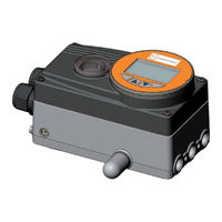
EBRO ARMATUREN EP 501 Operating Instructions Manual (205 pages)
Electropneumatic positioner and process controller
Brand:
EBRO ARMATUREN
| Category:
Controller
| Size: 2.41 MB
Table of Contents
Type Ep 501 T
3
Table of Contents
3
General Information and Safety Instructions
5
Operating.instructions
6
Symbols
6
Definition.of.the.term."Device
6
Authorized.use
7
Restrictions
7
Basic.safety.instructions
8
Safety.instructions.for.the.installation.and.maintenance.of.ex.devices
9
Basic.safety.instructions.for.use.in.the.ex.area
9
Use.in.the.ex.area
9
Scope.of.supply
10
Contact.address
10
Warranty
10
Master.code
10
General.information
10
Description of System Contents
11
Description of System
11
Description.and.features
13
Features
13
General.description
13
Combination with Valve Types and Mounting Versions
14
Designs
14
Type EP 501 C, Process Controller
14
Type EP 501, Positioner
14
Representation
15
Structure
15
Diagram Illustrating Single-Acting Actuator
16
Function.diagram
16
Positioner.type.ep.501
17
Schematic.representation.of.the.position.control
18
Positioner.software
19
Process.controller.type.ep.501.C
21
Schematic.representation.of.process.control
22
Type.ep.501.L.with.external.position.sensor
23
The.process.controller.software
24
Interfaces.of.the.positioner./.Process.controller
26
Conformity
27
Operating.conditions
27
Rating.plate.and.additional.plate.for.ex.devices
27
Standards
27
Technical.data
27
Mechanical.data
28
Electrical.data
29
Pneumatic.data
30
Installation Contents
33
Installation
33
Attachment.and.assembly
34
Attachment.to.a.continuous.valve.with.rotary.actuator
34
Installation
34
Safety.instructions
34
Connection and Start-Up Via a 4 - 20 Ma Path Sensor (for Type EP 501 L Only)
37
Remote.operation.with.external.position.sensor
37
Pneumatic.connection
39
Safety.instructions
39
Electrical.connection.-.Terminal.version.for.cable.gland
41
Connection.board.of.the.type.ep.501./.Ep.501.C.with.screw-Type.terminals
42
Input Signals from the Control Centre (E.g. PLC)
42
Terminal.assignment.for.cable.gland.-.Positioner.type.ep.501
42
Operating Voltage
43
Output Signals to the Control Centre (E.g. PLC) (Required for Analogue Output And/Or Binary Output Option Only)
43
Terminal Assignments of the Process Actual Value Input
44
Terminal.assignment.for.cable.gland.-.Process.controller.type.ep.501.C
44
Operation Contents
45
Operation
45
Operating.levels
46
Switching.between.the.operating.levels
46
Description.of.the.operating.and.display.elements
47
Operating.and.display.elements
47
Description of the Symbols Which Are Displayed on the Process Level
48
Function.of.the.keys
49
Entering and Changing Numerical Values
50
Adjusting.the.display
51
Possible Displays of the Process Level
51
Date.and.time
53
Setting Date and Time
54
Changing.the.operating.state
55
Operating.states
55
Activating Auxiliary Functions
56
Activating.and.deactivating.auxiliary.functions
56
Deactivating Auxiliary Functions
57
Manually.opening.and.closing.the.valve
58
Start-Up Contents
59
Start-Up
59
Safety.instructions
60
Start-Up.sequence
60
Basic.setting.of.the.device
61
INPUT.-.Setting.the.input.signal
62
X.TUNE.-.Automatic.adjustment.of.the.positioner
63
X.TUNE.CONFIG - Manual Configuration of X.TUNE
65
Activation.of.the.process.controller
66
Basic.setting.of.the.process.controller
67
P.CONTROL -.Setting.up.and.parameterization.of.the.process.controller
67
PV-INPUT - Specifying Signal Type for the Process Actual Value
69
SETUP.-.Setting.up.the.process.controller
69
PV-SCALE - Scaling of the Process Actual Value
70
SP-INPUT - Type of the Set-Point Value Default (Intern or Extern)
74
SP-SCALE - Scaling of the Process Set-Point Value (for External Set-Point Value Default Only)
74
P.CO-INIT - Smooth Switchover MANUAL-AUTOMATIC
76
PID.PARAMETER.-.Parameterizing.the.process.controller
77
Procedure for Inputting the Parameters
77
DBND - Insensitivity Range (Dead Band)
78
KP - Amplification Factor of the Process Controller
78
TN - Reset Time of the Process Controller
79
TV - Hold-Back Time of the Process Controller
79
X0 - Operating Point of the Process Controller
79
FILTER - Filtering of the Process Actual Value Input
80
P.Q'LIN.-.Linearization.of.the.process.characteristic
81
P.TUNE.-.Self-Optimization.of.the.process.controller
82
Preparatory Measure for Execution of
82
The Mode of Operation of
82
Starting the Function
84
Auxiliary Functions Contents
85
Auxiliary Functions
85
Activating.and.deactivating.auxiliary.functions
86
Configuring.the.auxiliary.functions
86
Including Auxiliary Functions in the Main Menu
86
Principle of Including Auxiliary Functions in the Main Menu
87
Removing Auxiliary Functions from the Main Menu
87
Overview.and.description.of.the.auxiliary.functions
88
CHARACT - Select the Transfer Characteristic between Input Signal (Position Set-Point Value) and Stroke
89
CUTOFF - Sealing Function
93
DIR.CMD - Sense of Effective Direction of the Positioner Set-Point Value
95
DIR.ACT - Sense of Effective Direction of the Actuator Drive
96
SPLTRNG - Signal Split Range
97
X.LIMIT - Limits the Mechanical Stroke Range
98
X.TIME - Limiting the Control Speed
99
X.CONTROL - Parameterization of the Positioner
100
P.CONTROL - Setting up and Parameterization of the Process Controller
101
SECURITY - Code Protection for the Settings
102
SAFEPOS - Input the Safety Position
104
SIG.ERROR - Configuration of Signal Level Fault Detection
105
BINARY.IN - Activation of the Binary Input
106
OUTPUT - Configuring the Outputs (Option)
108
CAL.USER - Calibration of Actual Value and Set-Point Value
114
SET.FACTORY - Resetting to the Factory Settings
119
SER. I\O - Settings of the Serial Interface
120
EXTRAS - Setting the Display
121
POS.SENSOR - Setting Interface Remote Path Sensor
124
Service
124
SIMULATION - Menu for Simulation of Set-Point Value, Process and Process Valve
125
DIAGNOSE - Menu for Monitoring Valves (Option)
130
Manual.configuration.of.X.tune
150
Description of the Menu for the Manual Configuration of X.TUNE
151
Operating Structure / Factory Settings
155
Operating.structure.and.factory.settings
156
Profibus Dp Contents
171
Profibus Dp
171
Description.of.the.profibus.dp
172
Interfaces
172
Technical.data
172
Bus.status.display
173
Changing.the.operating.state
173
Differences.between.the.field.bus.devices.and.devices.without.a.field.bus
173
Safety.settings.if.the.bus.fails
173
Electrical.connections
174
Connection.diagram.type.ep.501
175
X1.-.M12,.8-Pole.circular.connector
175
X2/X3.-.M12,.5-Pole.socket/Circular.connector.-.Bus.connection
176
Safety.instructions
177
Start-Up.profibus.dp
177
Start-Up.sequence
177
BUS.COMM - Settings.on.type.ep.501
178
Configuration of the Process Values
180
Configuration.via.the.control.(Profibus.dp.master)
180
Supplementary Literature on the Configuration of the PROFIBUS DP
180
Configuration.with.siemens.step7
182
Example of a Positioner (Type EP 501): Transfer of Set-Point and Actual Value
182
Maintenance and Troubleshooting Contents
183
Maintenance and Troubleshooting
183
Error.messages.and.malfunctions
184
Error.messages.on.the.display
184
General Error Messages
184
Maintenance
184
Error and Warning Messages While the X.TUNE Function Is Running
185
Error Messages While the P.Q'LIN Function Is Running
186
Error Messages While the P.TUNE Function Is Running
186
Error Messages on Field Bus Devices
187
Other.faults
187
Packaging, Storage, Disposal
188
Disposal
189
Packaging.and.transport
189
Storage
189
Additional Technical Information Contents
190
Additional Technical Information
190
Selection.criteria.for.continuous.valves
191
P-Portion
193
Properties.of.pid.controllers
193
I-Portion
194
D-Portion
195
Superposition.of.p,.I.and.D.portions
196
D Portion with Delay
197
Function of the Real PID Controller
197
Implemented.pid.controller
197
Adjustment.rules.according.to.ziegler.and.nichols.(Oscillation.method)
198
Adjustment.rules.for.pid.controllers
198
(Actuating.variable.jump.method)
200
Adjustment.rules.according.to.chien,.Hrones.and.reswick
200
Tables for Customer-Specific Settings
202
Advertisement
EBRO ARMATUREN EP 501 Quick Start Manual (95 pages)
Electropneumatic positioner and process controller
Brand:
EBRO ARMATUREN
| Category:
Valve Positioners
| Size: 1.51 MB
Table of Contents
English
3
Table of Contents
3
1 Quickstart
5
Definition of Term "Device
5
2 Symbols
5
3 Intended Use
6
Restrictions
6
4 Basic Safety Instructions
6
5 General Information
7
Scope of Supply
7
Contact Address
7
Warranty
7
Information on the Internet
7
6 Description Of System
8
General Description
8
Designs
8
Structure of the Device
9
7 Technical Data
9
Conformity
9
Standards
9
Operating Conditions
9
Type Labels
10
Mechanical Data
10
Electrical Data
10
Pneumatic Data
11
8 Operation
12
Description of the Operating and Display Elements
12
Function of the Keys
13
9 Operating States
14
Changing the Operating State
14
Displays in AUTOMATIC Mode
14
Master Code
15
10 Operating Levels
16
Switching between the Operating Levels
16
11 Attachment And Assembly
16
Installation of Devices for the Hazardous Area
16
Attachment to a Proportional Valve with Rotary Actuator
16
12 External Path Sensor
18
Connection of External Position Sensors for Type EP 501 L
19
13 Pneumatic Connection
19
Safety End Positions
20
14 Electrical Installation
22
Safety Instructions
22
Electrical Installation with Cable Gland
22
Terminal Assignment for Cable Gland - Positioner Type EP 501
23
Terminal Assignment for Cable Gland - Process Controller Type EP 501 C
24
Terminal Assignment for Cable Gland - Typ EP 501 L
25
15 Profibus Dp
25
Designation of the Circular Connectors and Contacts Type EP 501 P
25
Electrical Installation PROFIBUS
26
Electrical Connection PROFIBUS
28
16 Start-Up
28
Safety Instructions
28
Starting-Up Type EP 501
28
Start-Up Type EP 501 C
30
17 Packaging, Transport, Storage
32
18 Disposal
32
Deutsch
33
1 Der Quickstart
35
Begriffsdefinition Gerät
35
2 Darstellungsmittel
35
3 Bestimmungsgemässe Verwendung
36
Beschränkungen
36
4 Grundlegende Sicherheitshinweise
37
5 Allgemeine Hinweise
38
Lieferumfang
38
Kontaktadresse
38
Gewährleistung
38
Informationen IM Internet
38
6 Systembeschreibung
38
Allgemeine Beschreibung
38
Ausführungen
38
Aufbau des Geräts
39
7 Technische Daten
40
Konformität
40
Normen
40
Betriebsbedingungen
40
Typschilder
40
Mechanische Daten
41
Elektrische Daten
41
Pneumatische Daten
42
8 Bedienung
42
Beschreibung der Bedien- und Anzeigeelemente
42
Funktion der Tasten
43
9 Betriebszustände
44
Wechsel des Betriebszustands
44
Anzeigen IM AUTOMATIK-Betrieb
45
Mastercode
46
10 Bedienebenen
46
Wechsel zwischen den Bedienebenen
46
11 Anbau Und Montage
47
Montage von Geräten für den Ex-Bereich
47
Anbau an ein Stetigventil mit Schwenkantrieb
47
12 Externer Wegsensor
49
Anschluss Externer Wegsensor
49
13 Pneumatischer Anschluss
50
Sicherheitsendlagen
51
14 Elektrische Installation
52
Sicherheitshinweise
52
Elektrische Installation mit Kabelverschraubung
53
Klemmenbelegung bei Kabelverschraubung - Positioner Typ EP 501
53
Klemmenbelegung bei Kabelverschraubung - Prozessregler Typ EP 501 C
54
Klemmenbelegung bei Kabelverschraubung - Typ EP 501 L
55
15 Profibus Dp
56
Bezeichnung der Rundsteckverbinder und Kontakte Typ EP 501 P
56
Elektrische Installation PROFIBUS
56
Elektrischer Anschluss PROFIBUS
58
16 Inbetriebnahme
59
Sicherheitshinweise
59
Inbetriebnahme Typ EP 501
59
Inbetriebnahme Typ EP 501 C
61
17 Verpackung, Transport, Lagerung
63
18 Entsorgung
63
Français
64
1 Quickstart
66
Définition du Terme « Appareil
66
2 Symboles
66
3 Utilisation Conforme
67
Restrictions
67
4 Consignes De Sécurité Fondamentales
68
5 Indications Générales
69
Fourniture
69
Adresse
69
Garantie Légale
69
Informations Sur Internet
69
6 Description Du Système
69
Description Générale
69
Versions
70
Structure de L'appareil
70
7 Caractéristiques Techniques
71
Conformité
71
Normes
71
Conditions D'exploitation
71
Plaques Signalétiques
71
Caractéristiques Mécaniques
72
Caractéristiques Électriques
72
Caractéristiques Pneumatiques
73
8 Commande
73
Description des Éléments de Commande Et D'affichage
73
Fonction des Touches
74
9 Etats De Marche
75
Changement D'état de Marche
75
Affichage en L'état de Marche AUTOMATIQUE
76
Mastercode
77
10 Niveaux De Commande
77
Passage entre Les Niveaux de Commande
77
11 Ajout Et Montage
78
Montage D'appareils Pour Une Zone Ex
78
Montage Sur Une Vanne Continue Avec Actionneur Pivotant
78
12 Système Externe De Mesure De Déplacement
80
Raccordement du Système de Mesure de Déplacement Externe
80
13 Raccord Pneumatique
81
Positions Finales de Sécurité
82
14 Installation Électrique
83
Consignes de Sécurité
83
Raccordement Électrique Avec Presse-Étoupe
84
Affectation des Bornes Pour Presse-Étoupe
84
Positionneur Type EP 501
84
Affectation des Bornes Pour Presse-Étoupe - Régulateur de Process Type EP 501 C
85
Affectation des Bornes Pour Presse-Étoupe - Typ EP 501 L
86
15 Profibus Dp
87
Désignation des Connecteurs Ronds Et des Contacts Type EP 501 P
87
Installation Électrique PROFIBUS
87
Installation Électrique PROFIBUS
89
16 Mise En Service
90
Consignes de Sécurité
90
Mise en Service Type EP 501
90
Mise en Service Type EP 501 C
92
17 Emballage, Transport
94
18 Elimination
94
Advertisement
Related Products
EBRO ARMATUREN EP 501 B
EBRO ARMATUREN EP100
EBRO ARMATUREN EP 501 C
EBRO ARMATUREN EP 501 L
EBRO ARMATUREN SBU
EBRO ARMATUREN SBU IO-Link
EBRO ARMATUREN Categories
Valve Positioners
Controller
More EBRO ARMATUREN Manuals
Login
Sign In
OR
Sign in with Facebook
Sign in with Google
Upload manual
Upload from disk
Upload from URL