
Subscribe to Our Youtube Channel
Related Manuals for EBRO ARMATUREN EP 501 C

Summary of Contents for EBRO ARMATUREN EP 501 C
- Page 1 Type EP 501 Electropneumatic positioner and process controller Operating Instructions...
- Page 2 We reserve the right to make technical changes without notice. Technische Änderungen vorbehalten. Sous réserve de modification techniques. Operating Instructions 1710/01_EU-en_00810559 / Original DE...
-
Page 3: Table Of Contents
Type EP 501 Table of contents able of conTenTs GENERAL INFORMATION AND SAFETY INSTRUCTIONS.....................5 Operating.instructions................................6 Authorized.use..................................7 Basic.safety.instructions..............................8 Use.in.the.Ex.area..................................9 General.information................................10 DESCRIPTION OF SYSTEM..................................11 Description.and.features..............................13 Structure....................................15 Positioner.Type.EP.501..............................17 Process.controller.Type.EP.501.C..........................21 Interfaces.of.the.positioner./.process.controller....................26 10.. Technical.data..................................27 11.. - Page 4 Type EP 501 Table of contents AUXILIARY FUNCTIONS...................................85 24.. Configuring.the.auxiliary.functions..........................86 OPERATING STRUCTURE / FACTORY SETTINGS........................ 155 Operating.structure.and.factory.settings......................156 25.. PROFIBUS DP......................................171 Description.of.the.PROFIBUS.DP..........................172 26.. 27.. Electrical.connections..............................174 28.. Start-up.PROFIBUS.DP..............................177 MAINTENANCE AND TROUBLESHOOTING..........................183 Maintenance..................................
-
Page 5: General Information And Safety Instructions
Typ EP 501 General information and safety instructions onTenTs OPERATING.INSTRUCTIONS.................................6 1.1.. Symbols.......................................6 1.2.. Definition.of.the.term.“device”............................6 AUTHORIZED.USE....................................7 2.1.. Restrictions....................................7 BASIC.SAFETY.INSTRUCTIONS..............................8 USE.IN.THE.EX.AREA..................................9 4.1.. Basic.safety.instructions.for.use.in.the.Ex.area....................9 4.2.. Safety.instructions.for.the.installation.and.maintenance.of.Ex.devices..........9 GENERAL.INFORMATION................................10 5.1.. Scope.of.supply..................................10 5.2.. Contact.address...................................10 5.3.. Warranty....................................10 5.4.. Master.code....................................10 english... -
Page 6: Operating.instructions
→ designates a procedure that must be carried out. 1.2. Definition of the term “device” In these instructions, the term “device” always refers to the Type EP 501, EP 501 C or EP 501 L english... -
Page 7: Authorized.use
Typ EP 501 General information Safety instructions AUTHORIZED USE Incorrect.use.of.the.device.can.be.dangerous.to.people,.nearby.equipment.and.the.environment.. The device is designed for the open-loop control and closed-loop control of media. ▶ If using the device in the potentially explosive area, observe the specifications on the additional plate for Ex devices. -
Page 8: Basic.safety.instructions
Typ EP 501 General information Safety instructions BASIC SAFETY INSTRUCTIONS These safety instructions do not make allowance for any • contingencies and events which may arise during the installation, operation and maintenance of the devices. • local safety regulations – the operator is responsible for observing these regulations, also with reference to the installation personnel. -
Page 9: Use.in.the.ex.area
Typ EP 501 General information Safety instructions USE IN THE EX AREA 4.1. Basic safety instructions for use in the Ex area DANGER! Risk.of.explosion. To prevent the risk of explosion, observe not only the basic safety instructions in the respective operating instructions for operation in the Ex area, but also the following: ▶... -
Page 10: General.information
We will provide you with attachment kit for rotary actuators as accessory. If there are any discrepancies, please contact us immediately. 5.2. Contact address Germany EBRO ARMATUREN Gebr. Bröer GmbH Karlstraße 8 D-58135 Hagen Tel. + 49 (0) 2331 - 904 0 Fax + 49 (0) 2331 - 904 111 E-mail: post@ebro-armaturen.com... -
Page 11: Description Of System
6.1.1. Features ..............................13 6.1.2. Combination with valve types and mounting versions ..............14 6.2.. Designs.....................................14 6.2.1. Type EP 501, positioner ........................14 6.2.2. Type EP 501 C, process controller .....................14 STRUCTURE......................................15 7.1.. Representation..................................15 7.2.. Function.diagram.................................16 7.2.1. Diagram illustrating single-acting actuator ..................16 POSITIONER.TYPE.EP.501................................17... - Page 12 Typ EP 501 Description of System 11.8.. Safety.end.positions.after.failure.of.the.electrical.or.pneumatic.auxiliary.power......31 11.9.. Factory.settings..................................32 english...
-
Page 13: Description.and.features
DESCRIPTION AND FEATURES 6.1. General description The positioner Type EP 501 / process controller Type EP 501 C is a digital, electro-pneumatic positioner for pneumatically actuated continuous valves. The device incorporates the main function groups - Position sensor - Electro-pneumatic control system - Microprocessor electronics The position sensor measures the current positions of the continuous valve. -
Page 14: Combination With Valve Types And Mounting Versions
In this design, no spring is installed in the actuator. Two basic device versions are offered for the positioner Type EP 501 / process controller Type EP 501 C; they differ in the attachment option and in the position sensor. -
Page 15: Structure
Description of System STRUCTURE The positioner Type EP 501 and process controller Type EP 501 C consist of the micro-processor controlled elec- tronics, the position sensor and the control system. The device is designed using three-wire technology. Operation is controlled by four keys and a 128x64 dot matrix graphics display. -
Page 16: Function.diagram
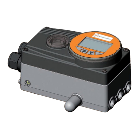
2: Bleed valve Figure 2: Structure, positioner Type EP 501 / process controller EP 501 C The remote design has the position sensor situated outside the device directly on the continuous valve and is connected to the latter by a cable. -
Page 17: Positioner.type.ep.501
Typ EP 501 Description of System POSITIONER TYPE EP 501 The position sensor records the current position (POS) of the pneumatic actuator. The positioner compares this actual position value with the set-point value (CMD) which is specified as a standard signal. If there is a control dif- ference (Xd1), the actuator is aerated and deaerated via the control system. -
Page 18: Schematic.representation.of.the.position.control
Typ EP 501 Description of System 8.1. Schematic representation of the position control Figure 4: Schematic representation of position control english... -
Page 19: Positioner.software
Typ EP 501 Description of System 8.2. Positioner software Configurable.auxiliary.functions Effect Correction line to adjust the operating characteristic Selection of the transfer characteristic between input signal and stroke (correction characteristic) CHARACT Sealing function Valve closes tight outside the control range. Specification of the value (in %), from which the actuator is completely CUTOFF deaerated (when 0%) or aerated (when 100%). - Page 20 Typ EP 501 Description of System Configurable.auxiliary.functions Effect Setting display Adjustment of the display of the process level EXTRAS SERVICE For internal use only POS.SENSOR Setting interface remote path sensor (available for Type EP 501 L only. See chapter “24.2.19. POS.SENSOR – Setting interface remote path sensor”.
-
Page 21: Process.controller.type.ep.501.C
PROCESS CONTROLLER TYPE EP 501 C In the case of process controller Type EP 501 C the position control mentioned in Chapter “8” becomes the subor- dinate auxiliary control circuit; this results in a cascade control. The process controller in the main control circuit of Type EP 501 C has a PID function. -
Page 22: Schematic.representation.of.process.control
Typ EP 501 Description of System 9.1. Schematic representation of process control Figure 6: Schematic representation of process control english... -
Page 23: Type.ep.501.L.with.external.position.sensor
Description of System 9.2. Type EP 501 L with external position sensor In the case of this model, the Type EP 501 C has no position sensor in the form of a rotary position sensor, but an external path sensor. Function. -
Page 24: The.process.controller.software
Typ EP 501 Description of System 9.3. The process controller software Configurable.auxiliary.functions Effect Correction line to adjust the operating characteristic Selection of the transfer characteristic between input signal and stroke (correction characteristic) CHARACT Sealing function Valve closes tight outside the control range. Specification of the value (in %), from which the actuator is completely CUTOFF deaerated (when 0%) or aerated (when 100%). - Page 25 Typ EP 501 Description of System Configurable.auxiliary.functions Effect SERVICE For internal use only Simulation software For simulation of the device functions SIMULATION DIAGNOSE (Option) Monitoring of processes POS.SENSOR Setting interface remote path sensor (available for Type EP 501 L only. See chapter “24.2.19. POS.SENSOR – Setting interface remote path sensor”.
-
Page 26: Interfaces.of.the.positioner./.Process.controller
Figure 7: Interfaces of the positioner / process controller The Types EP 501 and EP 501 C are 3-wire devices, i.e. the power (24 V DC) is supplied separately from the set-point value signal. * only for process controller Type EP 501 C... -
Page 27: Technical.data
Typ EP 501 Description of System TECHNICAL DATA 11.1. Conformity The device conforms with the EU Directives according to the EU Declaration of Conformity. 11.2. Standards The applied standards, which verify conformity with the EU Directives, can be found on the EU-Type Examination Certificate and / or the EU Declaration of Conformity. -
Page 28: Mechanical.data
Typ EP 501 Description of System Additional.plate.for.Ex.devices: Devices, which may be used in the explosion-protected area, are identified by the additional plate for Ex devices. 1. Do not open under II 3 G Ex nA IIC T4 explosive atmosphere 2. In Hazardous Areas the surface II 3 D Ex tD A22 T135°C may only be cleaned with a wet towel Figure 9:... -
Page 29: Electrical.data
Typ EP 501 Description of System 11.6. Electrical data Connections 2 cable glands (M20 x 1.5) with screw-type terminals 0.14 – 1.5 mm circular plug-in connector Operating voltage 24 V DC ± 10% max. residual ripple 10% Power consumption < 5 W Input data for actual value signal 180 Ω... -
Page 30: Pneumatic.data
Typ EP 501 Description of System 11.7. Pneumatic data Control medium Neutral gases, air Quality classes in accordance with DIN ISO 8573-1 Dust content Class 7, max. particle size 40 µm, max. particle density 10 mg/m³ Water content Class 3, max. pressure dew point - 20 °C or min. 10 degrees below the lowest operating temperature Oil content Class X, max. - Page 31 Typ EP 501 Description of System 11.8. Safety end positions after failure of the electrical or pneumatic auxiliary power The safety end position depends on the pneumatic connection of the actuator to the working connections A1 or Safety.end.positions.after.failure.of.the Actuator.system Designation pneumatic..
- Page 32 Typ EP 501 Description of System 11.9. Factory settings The factory settings can be found in Chapter “25. Operating structure and factory settings”, page 156. The factory presets are highlighted in blue to the right of the menu in the operating structure. Examples: Representation Description...
-
Page 33: Installation
Typ EP 501 Installation Installation onTenTs 12.. ATTACHMENT.AND.ASSEMBLY..............................34 12.1.. Safety.instructions:................................34 12.2.. Attachment.to.a.continuous.valve.with.rotary.actuator..................34 12.2.1. Installation ............................34 12.3.. Remote.operation.with.external.position.sensor....................37 12.3.1. Connection and start-up via a 4 – 20 mA path sensor (for Type EP 501 L only) ....37 13.. PNEUMATIC.CONNECTION.................................39 13.1.. -
Page 34: Attachment.and.assembly
Typ EP 501 Installation ATTACHMENT AND ASSEMBLY The dimensions of the device and the different device versions can be found on the data sheet. 12.1. Safety instructions: WARNING! Risk.of.injury.from.improper.installation. ▶ Installation may be carried out by authorised technicians only and with the appropriate tools. Risk.of.injury.from.unintentional.activation.of.the.system.and.an.uncontrolled.restart. - Page 35 Typ EP 501 Installation Anti-twist.safeguard: Note.the.flat.side.of.the.shaft!.. One of the setscrews must be situated on the flat side of the shaft as an anti-twist safeguard (see “Figure 13”). Rotation.range.of.the.position.sensor:. The maximum rotation range of the position sensor is 180°. The shaft of the device may be moved within this range only. 180°...
- Page 36 Typ EP 501 Installation → Place the device with assembly bridge on the rotary actuator and attach (see “Figure 15”) Figure 15: Rotary actuator attachment If the X.TUNE ERROR 5 message is indicated on the graphics display after the X.TUNE function starts, the shaft of the device is not correctly aligned with the shaft of the actuator (see “Table 100: Error and warning message on X.TUNE”, page 185.
-
Page 37: Remote.operation.with.external.position.sensor
Table 9: Connection options of path sensor * If the path sensor is connected to the process controller Type EP 501 C via the analog interface, it can be operated only as a positioner. 12.3.1. Connection and start-up via a 4 – 20 mA path sensor (for Type EP 501 L only) When a 4 –... - Page 38 Typ EP 501 Installation Separate supply of the path sensor: → Connection according to input type “4 ... 20 mA - externally supplied”. → Attach remote sensor on the actuator. The correct procedure is described in the instructions for the path sensor. →...
-
Page 39: Pneumatic.connection
Typ EP 501 Installation PNEUMATIC CONNECTION 13.1. Safety instructions DANGER! Risk.of.injury.from.high.pressure.in.the.equipment. ▶ Before loosening the pneumatic lines and valves, turn off the pressure and vent the pneumatic lines. WARNING! Risk.of.injury.from.improper.installation. ▶ Installation may be carried out by authorized technicians only and with the appropriate tools. Risk.of.injury.from.unintentional.activation.of.the.system.and.an.uncontrolled.restart. - Page 40 Typ EP 501 Installation Procedure: → Apply supply pressure (1.4 – 7 bar) to the supply pressure connection P. For.single-acting.actuators.(control.function.A.and.B): → Connect one working connection (A1 or A2, depending on required safety position) to the chamber of the single-acting actuator. Safety positions see chapter “11.8.
-
Page 41: Electrical.connection.-.Terminal.version.for.cable.gland
▶ Following installation, ensure a controlled restart. Using.the.4.–.20.mA.set-point.value.input If several devices of Type EP 501 / EP 501 C are connected in series and the power supply to a device in this series connection fails, the input of the failed device becomes highly resistive. -
Page 42: Connection.board.of.the.type.ep.501./.Ep.501.C.with.screw-Type.terminals
The procedure is described in the following chapters. for Type EP 501: chapter “14.2. Terminal assignment for cable gland - positioner Type EP 501” for Type EP 501 C: chapter “14.3. Terminal assignment for cable gland - process controller Type EP 501 C” 14.2. -
Page 43: Output Signals To The Control Centre (E.g. Plc) (Required For Analogue Output And/Or Binary Output Option Only)
Typ EP 501 Installation 14.2.2. Output signals to the control centre (e.g. PLC) (required for analogue output and/or binary output option only) → Connect terminals according to the model (options) of the positioner. Terminal Configuration On.the.device.side External.circuit./.Signal.level 83 + Binary output 1 83 + 24 V / 0 V, NC / NO specific to operating voltage GND (terminal GND) -
Page 44: Terminal.assignment.for.cable.gland.-.Process.controller.type.ep.501.C
Typ EP 501 Installation 14.3. Terminal assignment for cable gland - process controller Type EP 501 C → First connect the process controller as described in chapter “14.2. Terminal assignment for cable gland - positioner Type EP 501” 14.3.1. Terminal assignments of the process actual value input Input.type*... -
Page 45: Operation
Typ EP 501 Operation Operation onTenTs 15.. OPERATING.LEVELS..................................46 15.1.. Switching.between.the.operating.levels.........................46 OPERATING.AND.DISPLAY.ELEMENTS..........................47 16.. 16.1.. Description.of.the.operating.and.display.elements..................47 16.1.1. Description of the symbols which are displayed on the process level ........48 16.2.. Function.of.the.keys................................49 16.2.1. Entering and changing numerical values ..................50 16.3.. -
Page 46: Operating.levels
Typ EP 501 Operation OPERATING LEVELS There is the process level and the setting level for the operation and setting of Type EP 501 / EP 501 C. Process.level:. The running process is displayed and operated on the process level. -
Page 47: Operating.and.display.elements
Typ EP 501 Operation OPERATING AND DISPLAY ELEMENTS The following chapter describes the operating and display elements of Type EP 501 / EP 501 C. 16.1. Description of the operating and display elements The device is operated by four keys and a 128x64 dot matrix graphics display. -
Page 48: Description Of The Symbols Which Are Displayed On The Process Level
Diagnosis active (optional; only available if the device has the additional Operation as software for the diagnosis) positioner X.CONTROL / Positioner active (symbol is indicated for Type EP 501 C only) Save EEPROM (is indicated during the save process) CUTOFF active SAFEPOS active... -
Page 49: Function.of.the.keys
Typ EP 501 Operation 16.2. Function of the keys The functions of the 4 operating keys differ depending on the operating state (AUTOMATIC or MANUAL) and operating level (process level or setting level). The key function which is active is displayed in the gray text field which is above the key. The description of the operating levels and operating states can be found in Chapter "15. -
Page 50: Entering And Changing Numerical Values
Typ EP 501 Operation 16.2.1. Entering and changing numerical values Changing.numerical.values.with.fixed.decimal.places: Key. Description.of.the.function Example. function Change to the next decimal place (from right to left). Arrow key After reaching the last decimal place, the display switches back to the first decimal place. Enter date and time. -
Page 51: Adjusting.the.display
Typ EP 501 Operation 16.3. Adjusting the display The display can be individually adjusted for the operation and monitoring of the process. • To do this, menu options can be activated for displaying the process level. POS and CMD are activated in the as-delivered state. - Page 52 Typ EP 501 Operation Possible.displays.in.AUTOMATIC.operating.state Graphical display of POS and CMD with time axis MENU CMD / POS (t) HOLD Time, weekday and date CLOCK 12:00 Thu..01. . . 0 9. . . 1 1 MENU INPUT INPUT X.TUNE Input signal for set-point position INPUT (0 ...
-
Page 53: Date.and.time
Typ EP 501 Operation 16.4. Date and time Date and time are set on the process level in the CLOCK menu. To ensure that the input menu for CLOCK can be selected on the process level, the following functions must be activated in 2 stages: 1. -
Page 54: Setting Date And Time
Typ EP 501 Operation 16.4.1. Setting date and time: → On the process level select the display for CLOCK using the arrow keys. → Press INPUT to open the input screen for the setting. → Set date and time as described in the following table. Key. -
Page 55: Operating.states
Typ EP 501 Operation OPERATING STATES Type EP 501 / EP 501 C has 2 operating states: AUTOMATIC and MANUAL. When the operating voltage is switched on, the device is in the AUTOMATIC operating state. AUTOMATIC In the AUTOMATIC operating state normal controlled operation is implemented. -
Page 56: Activating.and.deactivating.auxiliary.functions
Typ EP 501 Operation ACTIVATING AND DEACTIVATING AUXILIARY FUNCTIONS Auxiliary functions can be activated for demanding control tasks. The auxiliary function is activated via the ADD.FUNCTION basic function and transferred to the main menu (MAIN). The auxiliary functions can then be selected and set in the extended main menu (MAIN). 18.1.1. -
Page 57: Deactivating Auxiliary Functions
Typ EP 501 Operation 18.1.1.1. Principle: Activating auxiliary functions with simultaneous incorporation into the main menu Functions in the main menu Setting.level (Standard) INPUT M A I N INPUT X.TUNE X.TUNE ADD.FUNCTION Activating the auxiliary function EXIT ENTER ADD.FUNCTION ENTER CHARACT EXTRAS DIAGNOSE... -
Page 58: Manually.opening.and.closing.the.valve
Typ EP 501 Operation MANUALLY OPENING AND CLOSING THE VALVE In the MANUAL operating state, the valve can be opened and closed manually using the arrow keys. The MANUAL operating state (key function ) is for the following process value displays: MANU •... -
Page 59: Start-Up
Typ EP 501 Start-Up Start-Up onTenTs START-UP.SEQUENCE...................................60 20.. 20.1.. Safety.instructions................................60 21.. BASIC.SETTING.OF.THE.DEVICE............................61 21.1.. .INPUT.-.Setting.the.input.signal..........................62 21.2.. .X.TUNE.–.Automatic.adjustment.of.the.positioner..................63 21.2.1. X.TUNE.CONFIG – Manual configuration of X.TUNE ..........65 22.. ACTIVATION.OF.THE.PROCESS.CONTROLLER.......................66 BASIC.SETTING.OF.THE.PROCESS.CONTROLLER......................67 23.. 23.1.. .P.CONTROL –.Setting.up.and.parameterization.of.the.process.controller........67 23.2.. .SETUP.–.Setting.up.the.process.controller.....................69 23.2.1. -
Page 60: Start-Up.sequence
Requirement type in.chapter Basic setting of the device: Set input signal INPUT "21.1" EP 510 (standard signal). essential EP 501 C Adjust device to the local X.TUNE "21.2" conditions. Activate process controller. ADD.FUNCTION "22" Basic setting of the process P.CONTROL "23"... -
Page 61: Basic.setting.of.the.device
Typ EP 501 Start-Up BASIC SETTING OF THE DEVICE The following settings must be made for the basic setting of the device: INPUT Selection of the input signal (see Chapter "21.1"). X.TUNE Automatic self-parameterization of the positioner (see Chapter "21.2") Operating structure for the basic setting: Process.level (values are displayed) Press for approx. -
Page 62: Input.-.Setting.the.input.signal
Typ EP 501 Start-Up 21.1. INPUT - Setting the input signal This setting is used to select the input signal for the set-point value. Procedure: Action Description Switching from process level setting level. MENU Press for approx. 3 s Select INPUT The possible input signals for INPUT are displayed. -
Page 63: X.tune.-.Automatic.adjustment.of.the.positioner
• Adjustment of the sensor signal to the (physical) stroke of the actuator used. • Determination of parameters of the PWM signals to control the solenoid valves integrated in Type EP 501 / EP 501 C. • Adjustment of the controller parameters for the positioner. Optimization occurs according to the criteria of the shortest possible transient time without overshoots. - Page 64 Typ EP 501 Start-Up Operating structure: Process.level (values are displayed) Press for approx. 3 s MENU Setting.level INPUT Automatic self-parameterization X.TUNE X.TUNE STARTED Hold.down as long as countdown TUNE #0 (5 ...) is INIT running X.TUNE READY EXIT ADD.FUNCTION EXIT Figure 24: Operating structure X.TUNE Automatically.determining.dead.band.DBND.by.running.X.TUNE:...
-
Page 65: X.tune.config - Manual Configuration Of X.tune
Typ EP 501 Start-Up Display Causes.of.error Remedial.action X.TUNE Control system aeration side leaking Not possible, device defective ERROR 4 X.TUNE The rotation range of the position sensor is Correct attachment of the position sensor ERROR 5 exceeded by 180° shaft on the actuator (see chapter "12.2"). X.TUNE The end positions for POS-MIN and Check compressed air supply... -
Page 66: Activation.of.the.process.controller
Typ EP 501 Start-Up ACTIVATION OF THE PROCESS CONTROLLER The process controller is activated by selecting the P.CONTROL auxiliary function in the ADD.FUNCTION menu. The activation transfers P.CONTROL into the main menu (MAIN) where it is available for further settings. Procedure: Action Description... -
Page 67: Basic.setting.of.the.process.controller
Typ EP 501 Start-Up BASIC SETTING OF THE PROCESS CONTROLLER 23.1. P.CONTROL – Setting up and parameterization of the process controller To start up the process controller, you must make the following settings in the P.CONTROL menu: SETUP Set up the process controller (configuration) PID.PARAMETER Parameterize process controller Operating structure:... - Page 68 Typ EP 501 Start-Up Procedure: Action Description Switching from process level setting level. MENU Press for approx. 3 s Select P.CONTROL Selection in the main menu (MAIN). The submenu options for basic settings can now be selected. ENTER Press 1..Set.up.process.controller.(configuration) Select SETUP The menu for setting up the process controller is displayed.
-
Page 69: Setup.-.Setting.up.the.process.controller
Typ EP 501 Start-Up 23.2. SETUP – Setting up the process controller These functions specify the type of control. The procedure is described in the following Chapters "23.2.1" to "23.2.5". 23.2.1. PV-INPUT – Specifying signal type for the process actual value One of the following signal types can be selected for the process actual value: •... -
Page 70: Pv-Scale - Scaling Of The Process Actual Value
Typ EP 501 Start-Up 23.2.2. PV-SCALE – Scaling of the process actual value The following settings are specified in the submenu of PV-SCALE: 1. The physical unit of the process actual value. PVmin 2. Position of the decimal point of the process actual value. 3. - Page 71 Typ EP 501 Start-Up 23.2.2.1. Effects and dependencies of the settings of PV-INPUT on PV-SCALE The settings in the PV-SCALE menu have different effects, depending on the signal type selected in PV-INPUT. Even the selection options for the units of the process actual value (in PVmin) depend on the signal type selected in PV-INPUT.
- Page 72 Typ EP 501 Start-Up For internal set-point value default (SP-INPUT → intern), the process set-point value is input directly on the process level. Example of a sensor calibration for frequency signal type: Pulses Scaling: Flow-rate Process actual value: K-factor 100 pulses correspond to 10 liters (pulses/liter) Process set-point value: K-factor 1.25 correspond to 8 liters...
- Page 73 Typ EP 501 Start-Up Action Description 3..Setting.K-factor.(only.available.for.frequency.signal.type). Select K-factor The submenu for the setting of the K-factor is displayed. ENTER Press either Select VALUE Manual.input.of.the.K-factor.. The input screen is opened. The decimal point has a dark INPUT Press background. Specify position of the decimal point. Select decimal point The last digit of the value has a dark background.
-
Page 74: Sp-Input - Type Of The Set-Point Value Default (Intern Or Extern)
Typ EP 501 Start-Up 23.2.3. SP-INPUT – Type of the set-point value default (intern or extern) The SP-INPUT menu specifies how the default of the process set-point value is to be implemented. • Intern: Input of the set-point value on the process level •... - Page 75 Typ EP 501 Start-Up Operating structure: SP-SCALE ENTER SPmin INPUT Input lower process set-point value INPUT SPmax Input upper process set-point EXIT value Figure 31: Operating structure SP-SCALE Scaling.process.set-point.value.SETUP.→.SP-SCALE: Action Description Select SP-SCALE The submenu options for scaling of the process set-point value are ENTER Press displayed.
-
Page 76: P.co-Init - Smooth Switchover Manual-Automatic
Typ EP 501 Start-Up 23.2.5. P.CO-INIT – Smooth switchover MANUAL-AUTOMATIC The smooth switchover between the MANUAL and AUTOMATIC states can be activated or deactivated in the P.CO-INIT menu. Factory default setting: bumpless Smooth switchover activated. Operating structure: SELEC Smooth switchover activated P.CO-INIT ENTER bumpless... -
Page 77: Pid.parameter.-.Parameterizing.the.process.controller
Typ EP 501 Start-Up 23.3. PID.PARAMETER – Parameterizing the process controller The following control parameters of the process controller are manually set in this menu. DBND 1.0 % Insensitivity range (dead band) of the process controller 1.00 Amplification factor of the (P-contribution of the PID controller) 999.0 Reset time (I-contribution of the PID controller) Hold-back time (D-contribution of the PID controller) -
Page 78: Dbnd - Insensitivity Range (Dead Band)
Typ EP 501 Start-Up 23.3.2. DBND – Insensitivity range (dead band) This function causes the process controller to respond from a specific control difference only. This protects both the solenoid valves in the device and the pneumatic actuator. Factory setting: 1.0 % with reference to the range of the scaled process actual value (setting in the menu PV-SCALE →... -
Page 79: Tn - Reset Time Of The Process Controller
Typ EP 501 Start-Up 23.3.4. TN – Reset time of the process controller The reset time specifies the I-contribution of the PID controller (can be set with the aid of the P.TUNE function). Factory setting: 999.9 s Operating structure: DBND 1.0 % PID.PARAMETER ENTER Input value... -
Page 80: Filter - Filtering Of The Process Actual Value Input
Typ EP 501 Start-Up 23.3.7. FILTER – Filtering of the process actual value input The filter is valid for all process actual value types and has a low pass behavior (PT1). Factory setting: 0 Operating structure: PID.PARAMETER DBND 1.0 % ENTER FILTER INPUT... -
Page 81: P.q'lin.-.Linearization.of.the.process.characteristic
Typ EP 501 Start-Up 23.4. P.Q‘LIN – Linearization of the process characteristic This function automatically linearizes the process characteristic. In doing so, the nodes for the correction characteristic are automatically determined. To do this, the program moves through the valve stroke in 20 steps and measures the associated process variable. The correction characteristic and the associated value pairs are saved in the menu option CHARACT →... -
Page 82: P.tune.-.Self-Optimization.of.the.process.controller
(KP, TN, TV). This is where they can be viewed and changed. Explanation.of.the.PID.controller: The control system of Type EP 501 C has an integrated PID process controller. Any process variable, such as flow rate, temperature, pressure, etc., can be controlled by connecting an appropriate sensor. - Page 83 Typ EP 501 Start-Up 23.5.2.1. Preparatory measures for execution of P.TUNE in the MANUAL operating state Moving.process.actual.value.PV.to.the.operating.point: Action Description Setting.on.the.process.level: Select PV The process actual value PV is indicated on the display. Change to MANUAL operating state.The input screen for manually MANU Press opening and closing the valve is displayed.
-
Page 84: Starting The Function
Typ EP 501 Start-Up 23.5.3. Starting the function P.TUNE WARNING! Risk.of.injury.from.uncontrolled.process. While the P.TUNE function is running, the control valve automatically changes the current degree of opening and intervenes in the running process. ▶ Using suitable measures, prevent the permitted process limits from being exceeded. For example by: - an automatic emergency shutdown - stopping the P.TUNE function by pressing the STOP key (press left or right key). -
Page 85: Auxiliary Functions
Typ EP 501 Auxiliary functions Auxiliary functions onTenTs CONFIGURING.THE.AUXILIARY.FUNCTIONS........................86 24.. 24.1.. Activating.and.deactivating.auxiliary.functions....................86 24.1.1. Including auxiliary functions in the main menu ................86 24.1.2. Removing auxiliary functions from the main menu ..............87 24.1.3. Principle of including auxiliary functions in the main menu ............87 24.2.. -
Page 86: Configuring.the.auxiliary.functions
Typ EP 501 Auxiliary functions CONFIGURING THE AUXILIARY FUNCTIONS The device has auxiliary functions for demanding control tasks. This chapter describes how the auxiliary functions are activated, set and configured. 24.1. Activating and deactivating auxiliary functions The required auxiliary functions must be activated by the user initially by incorporation into the main menu (MAIN). The parameters for the auxiliary functions can then be set. -
Page 87: Removing Auxiliary Functions From The Main Menu
Typ EP 501 Auxiliary functions 24.1.2. Removing auxiliary functions from the main menu If a function is removed from the main menu, the settings implemented previously under this function become invalid again. Procedure: Action Description Switching from process level setting level. MENU Press for approx. -
Page 88: Overview.and.description.of.the.auxiliary.functions
Typ EP 501 Auxiliary functions 24.2. Overview and description of the auxiliary functions Selection of the transfer characteristic between input signal ADD.FUNCTION CHARACT ENTER and stroke (correction characteristic) Sealing function for positioner CUTOFF Sense of effective direction between input signal and set- DIR.CMD point position Assignment of the aeration state of the actuator chamber to... -
Page 89: Charact - Select The Transfer Characteristic Between Input Signal (Position Set-Point Value) And Stroke
Typ EP 501 Auxiliary functions 24.2.1. CHARACT – Select the transfer characteristic between input signal (position set-point value) and stroke Characteristic (customer-specific characteristic) Use this auxiliary function to select a transfer characteristic with reference to set-point value (nominal position, CMD) and valve stroke (POS) for correction of the flow-rate or operating characteristic. - Page 90 Typ EP 501 Auxiliary functions Standardised valve stroke [%] (POS) Position set-point value [%] Figure 43: Characteristics In the case of control tasks for closed-loop control systems it is usually particular demands which are placed on the course of the operating characteristic, e.g. linearity. For this reason it is occasionally necessary to correct the course of the operating characteristic in a suitable way.
- Page 91 Typ EP 501 Auxiliary functions Procedure: Action Description Switching from process level setting level. MENU Press for approx. 3 s Select CHARACT (To do this, the auxiliary function must be incorporated into the main menu). Menu options of CHARACT are displayed. ENTER Select FREE The graphical display of the characteristic is displayed.
- Page 92 Typ EP 501 Auxiliary functions Example.of.a.programmed.characteristic Valve stroke [%] (POS) Standard signal [%] (CMD) 90 100 4 ... 20 mA 0 ... 20 mA 0 ... 10 V 0 ... 5 V Figure 45: Example of a programmed characteristic In the section “Tables for customer-specific settings” in chapter “37.1. Settings of the freely program- mable characteristic”...
-
Page 93: Cutoff - Sealing Function
Typ EP 501 Auxiliary functions 24.2.2. CUTOFF – Sealing function This function causes the valve to be sealed outside the control area. This is where you input the limits for the position set-point value (CMD) as a percentage, from which the actuator is fully deaerated or aerated. - Page 94 Typ EP 501 Auxiliary functions Valve stroke [%] Adjustable from 75 ... 100 % (POS) Set-point value [%] (CMD) einstellbar von 0 ... 25 % Figure 47: Graph - CUTOFF; english...
-
Page 95: Dir.cmd - Sense Of Effective Direction Of The Positioner Set-Point Value
Typ EP 501 Auxiliary functions 24.2.3. DIR.CMD – Sense of effective direction of the positioner set-point value Use this auxiliary function to set the sense of effective direction between the input signal (INPUT) and the nominal position (CMD) of the actuator. Each auxiliary function, which is to be set, must be incorporated initially into the main menu (MAIN). -
Page 96: Dir.act - Sense Of Effective Direction Of The Actuator Drive
Typ EP 501 Auxiliary functions 24.2.4. DIR.ACT – Sense of effective direction of the actuator drive Use this auxiliary function to set the sense of effective direction between the aeration state of the actuator and the actual position (POS). Factory setting: Rise Direct effective direction Rise DIR.ACT... -
Page 97: Spltrng - Signal Split Range
Typ EP 501 Auxiliary functions 24.2.5. SPLTRNG – Signal split range Min. and max. values of the input signal as % for which the valve runs through the entire stroke range. Factory setting: Min = 0 %; Max = 100 % Type.EP.501.C: The SPLTRNG auxiliary function can only be selected when operating as a positioner. -
Page 98: X.limit - Limits The Mechanical Stroke Range
Typ EP 501 Auxiliary functions 24.2.6. X.LIMIT – Limits the mechanical stroke range This auxiliary function limits the (physical) stroke to specified % values (minimum and maximum). In doing so, the stroke range of the limited stroke is set equal to 100 %. If the limited stroke range is left during operation, negative POS values or POS values greater than 100 % are indicated. -
Page 99: X.time - Limiting The Control Speed
Typ EP 501 Auxiliary functions 24.2.7. X.TIME – Limiting the control speed Use this auxiliary function to specify the opening and closing times for the entire stroke and limit the control speeds. When the X.TUNE function is running, the minimum opening and closing time for the entire stroke is auto- matically entered for Open and Close. -
Page 100: X.control - Parameterization Of The Positioner
Typ EP 501 Auxiliary functions 24.2.8. X.CONTROL – Parameterization of the positioner This function can be used to re-adjust the parameters of the positioner. The re-adjustment should only be made if it is required for the application. The parameters for X.CONTROL are automatically set with the exception of DBND (dead band) when specifying the basic settings by running X.TUNE. -
Page 101: P.control - Setting Up And Parameterization Of The Process Controller
Typ EP 501 Auxiliary functions Xd1‘ Position set- Control to the point value difference controller Xd1‘ Dead zone Position actual value Figure 59: Graph - X.CONTROL 24.2.9. P.CONTROL – Setting up and parameterization of the process controller Parameterization of the process controller is described in Chapter “23.1. P.CONTROL – Setting up and param- eterization of the process controller”... -
Page 102: Security - Code Protection For The Settings
Typ EP 501 Auxiliary functions 24.2.10. SECURITY – Code protection for the settings Use the SECURITY function to prevent the device or individual functions from being accessed unintentionally. Factory setting: Access Code: 0000 If the code protection is activated, the code (set access code or master code) must be input whenever operator action is disabled. - Page 103 * If you have forgotten the set code: All operator actions can be implemented with the non-changeable master code. This 4-digit master code can be found in the printed brief instructions for Type EP 501 C. english...
-
Page 104: Safepos - Input The Safety Position
Typ EP 501 Auxiliary functions 24.2.11. SAFEPOS – Input the safety position This function specifies the actuator safety position which is started at defined signals. The set safety position is only started • if there is a corresponding signal on the binary input (Configuration see chapter “24.2.13. -
Page 105: Sig.error - Configuration Of Signal Level Fault Detection
1. INPUT (for Types EP 501 and EP 501 C): See Chapter “21.1. INPUT - Setting the input signal”. 2. P.CONTROL (for Type EP 501 C and when process controller activated): See Chapter “23.2.1. PV-INPUT – Specifying signal type for the process actual value”. -
Page 106: Binary.in - Activation Of The Binary Input
Typ EP 501 Auxiliary functions 24.2.12.1. Behavior of the actuator when safety position deactivated or activated Selection SafePos off – The actuator remains in the position which corresponds to the set-point value last transferred (default setting). Selection SafePos on – Approaching the safety position activated: In the event of a signal fault detection, the behavior of the actuator depends on the activation of the SAFEPOS auxiliary function. - Page 107 X.TUNE.–.Starting.the.function.X.TUNE: → Binary input = 1 Starting X.TUNE X.CO/P.CO.–.Switching.between.position.and.process.controller: This menu option stands only for Type EP 501 C and is available when process controller (P.CONTROL) has been activated. → Positioner (X.CO) Binary input = 0 → Process controller (P.CO) Binäreingang = 1...
-
Page 108: Output - Configuring The Outputs (Option)
Typ EP 501 Auxiliary functions 24.2.14. OUTPUT – Configuring the outputs (option) The OUTPUT menu option is only indicated in the selection menu of ADD.FUNCTION if the device has outputs (option). The.device.which.has.the.outputs.option.is.available.in.the.following.versions: • one analogue output • one analogue and two binary outputs •... - Page 109 Typ EP 501 Auxiliary functions 24.2.14.2. OUT BIN1 / OUT BIN2 - Configuring the binary outputs The following description is valid for both binary outputs OUT BIN 1 and OUT BIN 2, as the operation in the menu is identical. The binary outputs 1 and 2 can be used for one of the following outputs: POS.Dev Exceeding the permitted control deviation...
- Page 110 Typ EP 501 Auxiliary functions Alarm output for exceeding the permitted control deviation OUT BIN1 Tolerance for the POS.Dev ENTER SELEC Input value OUT BIN2 permitted control Deviation: deviation Adjustment range: 1 ... 50 %** Output: current position with respect to a specified limit position Input the limit POS.Lim-1/2...
- Page 111 Typ EP 501 Auxiliary functions 24.2.14.3. Setting of the submenu options of OUT BIN 1 / OUT BIN 2 Action Description Switching from process level setting level. MENU Press for approx. 3 s Select OUTPUT (To do this, the auxiliary function must be incorporated into the main menu).
- Page 112 Typ EP 501 Auxiliary functions • Safepos.-.Outputting.the.message:.Actuator.in.safety.position • ERR.SP/CMD.-.Outputting.the.message:.Sensor.break.for.process.set-point.value/set-point.position. Only available if the function in the SIG.ERR menu has been activated (SIG.ERR → SP/CMD input → Error on). See Chapter “24.2.12. SIG.ERROR – Configuration of signal level fault detection”. • ERR.PV -.Outputting.the.message:.Sensor.break.for.process.actual.value.(only.for.Type.EP.501.C). Only available if the function in the SIG.ERR menu has been activated (SIG.ERR →...
- Page 113 Typ EP 501 Auxiliary functions • OUT.type.-.Setting.the.switching.status.. In addition to selecting the output, the switching status required for the binary output must be input. See “Table 55”. Action Description Select OUT.type The switching statuses normally open and normally closed are SELEC Press displayed.
-
Page 114: Cal.user - Calibration Of Actual Value And Set-Point Value
For the calibration process the signal type is displayed which was specified for the input signal. See Chapter “21.1. INPUT - Setting the input signal”. Type.EP.501.C: The following values can be calibrated only for Type EP 501 C and activated process controller (P.CONTROL). calibr. SP • Process set-point value (4 - 20 mA, 0 - 20 mA, 0 - 5 V, 0 - 10 V) For the calibration process the signal type is displayed which was specified for the input signal. - Page 115 ENTER INPUT Input value (POS.lower:) POS. pMAX INPUT EXIT Input value (POS.upper:) Only.for.positioner.Type.EP.501. (or for Type EP 501 C if P.CONTROL not activated). calibr. INP INP 4mA 0** ENTER INPUT Create and confirm minimum value INP 20mA 0** INPUT EXIT...
- Page 116 Typ EP 501 Auxiliary functions 24.2.15.1. Calibration of the position actual value and the position set- point value Action Description Switching from process level setting level. MENU Press for approx. 3 s Select CAL.USER (To do this, the auxiliary function must be incorporated into the main menu).
- Page 117 Typ EP 501 Auxiliary functions 24.2.15.2. Calibration of the process set-point value and process actual value Action Description Switching from process level setting level. MENU Press for approx. 3 s Select CAL.USER (To do this, the auxiliary function must be incorporated into the main menu).
- Page 118 Typ EP 501 Auxiliary functions 24.2.15.3. Resetting the settings under CAL.USER to the factory settings Action Description Switching from process level setting level. MENU Press for approx. 3 s Select CAL.USER (To do this, the auxiliary function must be incorporated into the main menu).
-
Page 119: Set.factory - Resetting To The Factory Settings
Typ EP 501 Auxiliary functions 24.2.16. SET.FACTORY – Resetting to the factory settings This function allows all settings implemented by the user to be reset to the delivery status. All EEPROM parameters with the exception of the calibration values are reset to default values. Then a hardware reset is implemented. -
Page 120: Ser. I\O - Settings Of The Serial Interface
Typ EP 501 Auxiliary functions 24.2.17. SER. I\O – Settings of the serial interface This function can be used to set the type of the serial interface and the baud rate. SELEC SER. I/O I/O.MODE HART ENTER ENTER Burst Automatic Auto EXIT switchover to... -
Page 121: Extras - Setting The Display
Typ EP 501 Auxiliary functions 24.2.18. EXTRAS – Setting the display This function can be used to individually set the display. • In DISP.ITEMS the display of the process level can be individually set. To do this, further menu options can be activated for the display of the process level. POS and CMD are acti- vated in the as-delivered state. - Page 122 The possible menu options are displayed. ENTER Press POS, CMD, CMDIPOS, CMD/POS(t), CLOCK, INPUT, TEMP, X.TUNE. Additionally for process controller Type EP 501 C: PV, SP, SPlPV, SP/PV(t), P.TUNE, P.LIN. Select required menu options SELEC Press Activate the selection by checking the box...
- Page 123 Typ EP 501 Auxiliary functions DISP.MODE.-.. S elect.type.of.display.. (black.font.on.light.background.or.white.font.on.dark.background): Action Description Switching from process level setting level. MENU Press for approx. 3 s Select ADD.FUNCTION The possible auxiliary functions are displayed. ENTER Press Select EXTRAS ENTER Press Activate the EXTRAS auxiliary function by checking the box transfer into the main menu.
-
Page 124: Pos.sensor - Setting Interface Remote Path Sensor
ANALOG): Type EP 501 C is connected via a 4 ... 20 mA interface to any path sensor with 4 ... 20 mA output signal. To do this, the path sensor is connected to the process actual value input (see Chapter “Terminal assignments of the process actual value input”, page 44). -
Page 125: Simulation - Menu For Simulation Of Set-Point Value, Process And Process Valve
Typ EP 501 Auxiliary functions 24.2.21. SIMULATION – Menu for simulation of set-point value, process and process valve This function can be used to simulate set-point value, process and process valve independently of each other. Caution! Restarting the device deactivates the simulation. The settings of SIGNAL.form, x.SIM and p.SIM are reset to the factory setting. - Page 126 Typ EP 501 Auxiliary functions 24.2.21.1. SIGNAL.sim – Simulation of the set-point value The settings to simulate the set-point value are made in the SIGNAL.sim menu. Activation.of.the.simulation: In the SIGNAL.form submenu by selecting one of the following waveforms Sine wave Sine Square wave Square...
- Page 127 Typ EP 501 Auxiliary functions Action Description Select SIGNAL.sim The submenu for activating and parameterizing the set-point value ENTER Press simulation is displayed. Select SIGNAL.form The menu options for activating and for selecting the waveform are ENTER Press displayed. Select required menu option Externally Selection = simulation inactive.
- Page 128 Typ EP 501 Auxiliary functions 24.2.21.2. CONTROL.sim – Simulation of the process and process valve The settings to simulate the process and the process valve are made in the CONTROL.sim menu. Settings Type of simulation: Simulation of the process valve. x.SIM Simulation of the process.
- Page 129 Typ EP 501 Auxiliary functions Action Description Select required simulation Selection x.SIM = simulation process. Selection p.SIM = simulation process valve. SELEC Press Activate the selection by checking the box or deactivate it by unchecking the box Setting the parameters for simulation of the process and/or the process valve: Select SIM.Gain (Amplification factor).
-
Page 130: Diagnose - Menu For Monitoring Valves (Option)
Typ EP 501 Auxiliary functions 24.2.22. DIAGNOSE – Menu for monitoring valves (option) The optional function DIAGNOSE can be used to monitor the state of the valve. If there are deviations from the set-point state, messages are output according to NE 107. Example of the output of a diagnosis message: Status signal Symbol for:... - Page 131 Typ EP 501 Auxiliary functions 24.2.22.3. DIAGNOSE – Operating structure Display all generated Select a diagnosis diagnosis messages message DIAGNOSE D. MSG ENTER SERVICE.TIME ENTER CLEAR ENTER Diagnosis Delete. message message POS.MONITOR EXIT displayed EXIT Assignment of status signals Display the diagnosis according to NE 107** functions* SELEC...
- Page 132 Direction reversal counter CYCLE.COUNTER Temperature monitor TEMP.CHECK Monitoring of the mechanical end positions in the armature STROKE.CHECK Process actual value monitoring (only for Type EP 501 C, process control) PV.MONITOR Position monitoring POS.MONITOR Table 67: ADD.DIAGNOSE; overview of diagnosis functions The exact description can be found in Chapter “24.2.22.6.
- Page 133 Typ EP 501 Auxiliary functions 24.2.22.5. Description of the DIAGNOSE main menu D.MSG –.Diagnosis.messages All generated diagnosis messages are listed in the D.MSG menu where they can be viewed and deleted. The status signal, which is assigned to the diagnosis message, is indicated by a symbol. Display example of a list with diagnosis messages Symbol for the assigned status Diagnosis...
- Page 134 Typ EP 501 Auxiliary functions If several diagnosis messages are available with different status signals, the status signal with the highest priority is shown on the display. Overview.of.the.status.signals.according.to.NE.107.(NE.=.NAMUR.recommendation):. Priority Status.signal Description Failure Function check Out of specification Maintenance required Table 70: CONFIG.MSG;...
- Page 135 Typ EP 501 Auxiliary functions ADD.DIAGNOSE –.Activation.and.deactivation.of.diagnosis.functions Diagnosis functions can be activated in this menu and incorporated into the DIAGNOSE main menu or already activated diagnosis functions can be deactivated again. Activation.of.diagnosis.functions: For description see Chapter “24.2.22.4. Activation of diagnosis functions” Deactivation.of.diagnosis.functions: The procedure is the same as for activation.
- Page 136 Typ EP 501 Auxiliary functions 24.2.22.6. Description of the diagnosis functions HISTOGRAM –.Output.of.histograms The HISTOGRAM menu is divided into 2 parts: 1... O utputting.the.histograms for POS class (dwell time density) and DIR class (movement range) 2. List.of.the.characteristic.values for CMD Set-point position valve actuator Actual position valve actuator Deviation from POS to CMD TEMP Temperature...
- Page 137 Typ EP 501 Auxiliary functions POS-Class - Description.of.the.histogram.of.the.dwell.time.density The histogram indicates how long the actuator has stopped in a specific position. For this purpose the stroke range is divided into 10 classes. The current position of one of the 10 classes is assigned to each scan time. <10 11 - 20 21 - 30...
- Page 138 Typ EP 501 Auxiliary functions DIR-Class - Description.of.the.histogram.of.the.movement.range The histogram indicates the movement ranges of the actuator between two direction reversal points. For this purpose the movement range between two changes in direction is divided into 10 classes. The current position of one of the 10 classes is assigned to each scan time. 0 - 10 11 - 20 21 - 30...
- Page 139 Typ EP 501 Auxiliary functions Starting,.stopping.and.deleting.the.histograms Action Description Select HISTOGRAM (To do this, the HISTOGRAM function must be incorporated into the DIAGNOSE main menu. See Chapter “24.2.22.4. Activation of diagnosis functions”). The empty matrix of the POS-Class submenu (dwell time density) is ENTER Press displayed.
- Page 140 Typ EP 501 Auxiliary functions SERVICE.TIME –.Operating-hours.counter The operating-hours counter records the time during which the device was switched on. If the duty cycle reaches the specified time limit, a message is generated. • To do this, a history entry is made in the HISTORY submenu. For description see “24.2.22.7. History entries in the HISTORY submenu”.
- Page 141 Typ EP 501 Auxiliary functions TRAVEL.ACCU –.Path.accumulator The path accumulator records and adds up the path which the actuator piston covers. A movement of the actuator piston is detected when the position changes by at least 1 %. The interval for outputting messages is specified by inputting a limit for the total number of piston movements. •...
- Page 142 Typ EP 501 Auxiliary functions Specifying.interval.for.the.output.of.messages Action Description Select TRAVEL.ACCU (To do this, the TRAVEL.ACCU function must be incorporated into the DIAGNOSE main menu. See Chapter “24.2.22.4. Activation of diagnosis functions”). The menu is displayed. ENTER Press * Required for analog position sensor only (setting the STROKE submenu) Select STROKE The preset value is displayed.
- Page 143 Typ EP 501 Auxiliary functions Operating structure: CYCLE.COUNTER LIMIT INPUT ENTER Input change in direction Display the remaining changes in direction until the next NEXT M. message Delete.history.entry HISTORY ENTER CLEAR EXIT History entry is displayed EXIT Figure 85: Operating structure CYCLE.COUNTER Specifying.interval.for.the.output.of.messages Action Description...
- Page 144 Typ EP 501 Auxiliary functions Display.TEMP.CHECK Description.of.the.functions CURRENT indicates the current temperature. TEMP.CHECK MAX indicates the highest temperature of the slave pointer 21.7. * C CURRENT 21.7 * C MIN indicates the lowest temperature of the slave pointer 21.7 * C The permitted temperature range can be changed in the LIMIT submenu.
- Page 145 Typ EP 501 Auxiliary functions Action Description Input upper temperature limit TEMP.MAX. Increase value < Changing the decimal place Acknowledge value. Press Select TEMP.MIN Open factory setting for lower temperature limit. INPUT Press Input lower temperature limit TEMP.MIN. Increase value <...
- Page 146 Typ EP 501 Auxiliary functions CAUTION! If a stroke limit was set in the X.LIMIT menu, the mechanical end position monitor has only limited relevance. The end positions indicated on the process level under POS are not the physically caused end positions in this case.
- Page 147 Typ EP 501 Auxiliary functions Action Description Acknowledge value. Press Return to the STROKE.CHECK menu. EXIT Press Return to the DIAGNOSE main menu. EXIT Press Table 84: STROKE.CHECK; end position monitor. POS.MONITOR –Position.monitoring The POS.MONITOR function monitors the current position of the actuator. The tolerance band for the set-point value is specified in the DEADBAND submenu.
- Page 148 Typ EP 501 Auxiliary functions Operating structure: ENTER DEADBAND POS.MONITOR INPUT Input tolerance band COMP.TIME INPUT Input compensation time Delete.history.entry HISTORY ENTER CLEAR EXIT History entry is displayed EXIT Figure 89: Operating structure POS.MONITOR Inputting.tolerance.band.and.compensation.time Action Description Select POS.MONITOR (To do this, the POS.MONITOR function must be incorporated into the DIAGNOSE main menu.
- Page 149 Typ EP 501 Auxiliary functions 24.2.22.7. History entries in the HISTORY submenu Each diagnosis function, which can output a message, has the HISTORY submenu. When the diagnosis message is actuated, a history entry is created with date and value. The history entries of the respective diagnosis function can be viewed and deleted in the HISTORY submenu.
-
Page 150: Manual.configuration.of.x.tune
Typ EP 501 Auxiliary functions 24.3. Manual configuration of X.TUNE This.function.is.needed.for.special.requirements.only.. For standard applications the X.TUNE function has been preset at the factory. See chapter “21.2. X.TUNE – Automatic adjustment of the positioner”. For special requirements the X.TUNE function, as described below, can be manually configured. Opening.the.menu.for.the.manual.configuration.of.X.TUNE Action Description... -
Page 151: Description Of The Menu For The Manual Configuration Of X.tune
Typ EP 501 Auxiliary functions 24.3.1. Description of the menu for the manual configuration of X.TUNE Configuration.of.the.X.TUNE. Specify which functions are to be executed when X.TUNE.CONFIG function X.TUNE is running (automatic self-optimization). Position.of.the.end.positions - Specify whether the pneumatic actuator has M.TUNE.POS mechanical end positions. - Page 152 Typ EP 501 Auxiliary functions 24.3.1.2. X.TUNE.POS – Setting of the end positions In this menu you can specify whether the pneumatic actuator has mechanical end positions or not. If there are no mechanical end positions available, these are not approached by the X.TUNE and must be man- ually specified.
- Page 153 Typ EP 501 Auxiliary functions 24.3.1.3. M.TUNE.PWM – Optimization of the PWM signals In this menu the PWM signals for control of the aeration valves and bleed valves are manually optimized. For optimization the actuator is aerated and bled. A progress bar on the display indicates the position of the actuator and the speed of aeration and deaeration.
- Page 154 Typ EP 501 Auxiliary functions 24.3.1.4. M.TUNE.AIR – Determination of the opening and closing times By running this function, the opening and closing times of the valve are determined continuously. A change to the supply pressure will affect the aeration time which can be optimized in this way. For the setting the effects, which a change to the supply pressure has on the aeration time, can be continuously monitored via the M.TUNE.AIR function.
-
Page 155: Operating Structure / Factory Settings
Typ EP 501 Operating structure / Factory settings Operating structure / Factory settings onTenTs 25.. OPERATING.STRUCTURE.AND.FACTORY.SETTINGS....................156 english... -
Page 156: Operating.structure.and.factory.settings
P.CONTRL active BUS PDO / Setpoint Operation mode Error reset P.CONTRL active X.TUNE Figure 91: Operating structure - 1 1) only process controller Type EP 501 C 2) only for positioner mode 3) only field bus 5) only PROFIBUS DP english... - Page 157 TUNE.yE M.TUNE.AIR time.open time.close P.Q‘LIN Q.LIN#0 Q.LIN#1 Q.LIN CMD=0% CMD=10% ... ready P.TUNE starting identifying calculating TUNE process tune control process PID parameters ready ADD.FUNCTION Figure 92: Operating structure - 2 1) only process controller Type EP 501 C english...
- Page 158 CHARACT Figure 93: Operating structure - 3 1) only process controller Type EP 501 C 2) only for positioner mode 6) only for signal type 4-20 mA and Pt 100 7) Optional. The number of outputs varies depending on the version.
- Page 159 100 % 100 % Type PCO CUT-type Type XCO DIR.CMD Rise Fall DIR.ACT Rise Fall SPLTRNG 100 % 100 % X.LIMIT Figure 94: Operating structure - 4 1) only process controller Type EP 501 C 2) only for positioner mode english...
- Page 160 1.0 % P.CONTROL PID.PARAMETER DBND 1.0 % 1.00 1.00 999.9 sec 999.9 0.0 sec FILTER SETUP PV-INPUT 4- 20 mA Frequenz PT 100 SECURITY PV-SCALE Figure 95: Operating structure - 5 1) only process controller Type EP 501 C english...
- Page 161 Type EP 501 C → → → only for signal type frequency (P.CONTROL SETUP PV-INPUT Frequency) → → 10) Only process controller Type EP 501 C and for external set-point value default (P.CONTROL SETUP SP-INPUT → external) english...
- Page 162 0 - 5 V CAL.USER OUT BIN 1 Figure 97: Operating structure - 7 only process controller Type EP 501 C only for signal type 4-20 mA and Pt 100 Optional. The number of outputs varies depending on the version english...
- Page 163 11) only if fault detection is activated for the input signal → → (SIG.ERROR SP/CMD Input or PV-Input Error on) 12) Only process controller Type EP 501 C and if fault detection is activated for the input signal → → (SIG.ERROR SP/CMD Input or PV-Input Error on)
- Page 164 38400 EXTRAS SERIAL.CONFIG Figure 99: Operating structure - 9 only process controller Type EP 501 C only for positioner mode 10) Only process controller Type EP 501 C and for external set-point value default → → → (P.CONTROL SETUP SP-INPUT...
- Page 165 ODD par., 2 Stop EXTRAS DISP.ITEMS CMD /POS CMD /POS (t ) SP /PV SP /PV (t ) CLOCK INPUT TEMP X.TUNE P.TUNE P.LIN SERVICE START-UP.ITEMS Figure 100: Operating structure- 10 only process controller Type EP 501 C 16) nicht bei Feldbus english...
- Page 166 TAN.CORRECTION tan.corr SERVICE 0° ALPHA +/- 0° SIMULATION Figure 101: Operating structure - 11 1) only process controller Type EP 501 C 8) for Type EP 501 L only 16) not for field bus 18) only NAMUR-version english...
- Page 167 DIAGNOSE SERVICE.TIME D.MSG TRAVEL.ACCU CYCLE.COUNTER TEMP.CHECK STROKE.CHECK PV.MONITOR POS.MONITOR SERVICE.TIME CONFIG.MSG FAILURE FUNC.CHECK OUT.SPEC MAINTENANCE ADD.DIAGNOSE TRAVEL.ACCU Figure 102: Operating structure - 12 only process controller Type EP 501 C 17) The submenu lists only the activated diagnosis functions english...
- Page 168 CYCLE.COUNTER FAILURE FUNC.CHECK OUT.SPEC MAINTENANCE TEMP.CHECK FAILURE FUNC.CHECK OUT.SPEC MAINTENANCE STROKE.CHECK FAILURE FUNC.CHECK OUT.SPEC MAINTENANCE FAILURE PV.MONITOR FUNC.CHECK OUT.SPEC MAINTENANCE POS.MONITOR FAILURE FUNC.CHECK OUT.SPEC MAINTENANCE ADD.DIAGNOSE Figure 103: Operating structure - 13 only process controller Type EP 501 C english...
- Page 169 Typ EP 501 Operating structure / Factory settings ADD.DIAGNOSE HISTOGRAM SERVICE.TIME TRAVEL.ACCU CYCLE.COUNTER TEMP.CHECK STROKE.CHECK PV.MONITOR POS.MONITOR RESET.HISTORY Reset done Aktivierbare.Diagnosefunktionen HISTOGRAM POS-Class DIR-Class SYSTEM-DATA SERVICE.TIME LIMIT 90d. 00h NEXT M. HISTORY 20.0 mm TRAVEL.ACCU 1000000 cm LIMIT NEXT.M HISTORY 1000000 CYCLE.COUNTER LIMIT...
- Page 170 0,5 % LIMIT LIMIT ZERO.TOL 0,5 % MAX.TOL HISTORY ZERO 2.0 % POS.MONITOR DEADBAND 10.0 sec COMP.TIME HISTORY 2.0 % DEADBAND PV.MONITOR 10.0 sec COMP.TIME HISTORY Figure 105: Operating structure - 15 only process controller Type EP 501 C english...
-
Page 171: Profibus Dp
Typ EP 501 PROFIBUS DP PROFIBUS DP onTenTs 26.. DESCRIPTION.OF.THE.PROFIBUS.DP..........................172 26.1.. Technical.data..................................172 26.2.. Interfaces....................................172 26.3.. Changing.the.operating.state............................. 173 26.4.. Safety.settings.if.the.bus.fails........................... 173 26.5.. Bus.status.display................................173 26.6.. Differences.between.the.field.bus.devices.and.devices.without.a.field.bus........173 ELECTRICAL.CONNECTIONS..............................174 27.. -
Page 172: Description.of.the.profibus.dp
Typ EP 501 PROFIBUS DP DESCRIPTION OF THE PROFIBUS DP 26.1. Technical data The protocol sequence complies with the standard DIN 19245 Part 3. GSD.file BUER0C1E.gsd Bitmap.files BUER0C1E.bmp PNO-ID. 0C1E Hex Baud.rate Max. 12 mbaud (is automatically set by the device) Sync.and.Freeze.mode Are not supported Diagnosis.telegram No device-specific diagnosis... -
Page 173: Changing.the.operating.state
Typ EP 501 PROFIBUS DP 26.3. Changing the operating state There are two ways of switching between the MANUAL and AUTOMATIC operating states for the PROFIBUS DP: • Input via the keyboard on the device: On the process level using the key function MANU AUTO •... -
Page 174: Electrical.connections
Typ EP 501 PROFIBUS DP ELECTRICAL CONNECTIONS DANGER! Risk.of.injury.due.to.electrical.shock. ▶ Before reaching into the device or the equipment, switch off the operating voltage and secure to prevent reactivation. ▶ Observe applicable accident prevention and safety regulations for electrical equipment. Risk.of.explosion.if.used.in.Ex.area. To avoid the risk of explosion, connect the Ex device to the power supply as described below: ▶... -
Page 175: Connection.diagram.type.ep.501
Typ EP 501 PROFIBUS DP 27.1. Connection diagram Type EP 501 X1 - M12, 8-pole circular connector X3 - M12, 5-pole X2 - M12, 5-pole socket *. circular connector * Functional earth FE *. (inversely coded, PROFIBUS DP) Figure 107: Connection PROFIBUS DP, positioner Typ EP 501 27.2. -
Page 176: X2/X3.-.M12,.5-Pole.socket/Circular.connector.-.Bus.connection
Typ EP 501 PROFIBUS DP 27.3. X2/X3 - M12, 5-pole socket/circular connector - bus connection Configuration External.circuit./.Signal.level Supply the terminating resistors VP+5 Received/transmitted data -N, A-line RxD/TxD-N Data transmission potential (earth to 5 V) DGND Received/transmitted data -P, B-line RxD/TxD-P Shielding / protective earth Shielding Table 94:... -
Page 177: Start-Up.profibus.dp
Typ EP 501 PROFIBUS DP START-UP PROFIBUS DP 28.1. Safety instructions WARNING! Risk.of.injury.from.improper.operation. Improper operation may result in injuries as well as damage to the device and the area around it ▶ Before start-up, ensure that the operating personnel are familiar with and completely understand the contents of the operating instructions. -
Page 178: Bus.comm - Settings.on.type.ep.501
Typ EP 501 PROFIBUS DP 28.3. BUS.COMM – Settings on Type EP 501 Set the following menu options in the BUS.COMM menu for start-up of the PROFIBUS DP: Enter.a.device.address.(value between 0 and 126) Address 0 Activate.or.deactivate.approach.of.the.safety.position BUS FAIL Selection SafePos off –... - Page 179 Typ EP 501 PROFIBUS DP Input device address. BUS.COMM ENTER Address INPUT Enter Adjustment range: 0 ... 126 value SELEC SafePos off Activating / BUS FAIL ENTER deactivating approach of the SafePos on EXIT safety position Setting.of.BUS.PDI.and.BUS.PDO.is.made.via.GSD.file SELEC Position BUS PDI ENTER Process values which are trans-...
-
Page 180: Configuration.via.the.control.(Profibus.dp.master)
Typ EP 501 PROFIBUS DP 28.4. Configuration via the control (PROFIBUS DP Master) The configuration requires the following components: • Software suitable for the configuration. For example Step7 from Siemens A brief description of this can be found in the following chapter “28.5. Configuration with Siemens Step7”. •... - Page 181 Typ EP 501 PROFIBUS DP Name Description Identifier PDI:ERR Error GSD file: PDI:ERR Indicates the number of the process value (output) which was not written. The value is retained until it is deleted with PDO:ERR. 14 PDO:CMD / SP 16 PDO:MODE Identifier (HEX): 41, 00, 06 Table 97: Process Data Input, PROFIBUS DP...
-
Page 182: Configuration.with.siemens.step7
Typ EP 501 PROFIBUS DP 28.5. Configuration with Siemens Step7 28.5.1. Example of a positioner (Type EP 501): Transfer of set- point and actual value Figure 109: ScreenShot PROFIBUS → Pull the slave Type EP 501 onto the bus line with drag-and-drop. Figure 110: ScreenShot positioner →... -
Page 183: Maintenance And Troubleshooting
Typ EP 501 Maintenance and Troubleshooting Maintenance and Troubleshooting onTenTs 29.. MAINTENANCE....................................184 30.. ERROR.MESSAGES.AND.MALFUNCTIONS........................184 30.1.. Error.messages.on.the.display..........................184 30.1.1. General error messages ......................184 30.1.2. Error and warning messages while the X.TUNE function is running ......185 30.1.3. -
Page 184: Maintenance
Typ EP 501 Maintenance and Troubleshooting MAINTENANCE The.device.is.maintenance-free.when.operated.according.to.the.instructions.in.this.manual. ERROR MESSAGES AND MALFUNCTIONS 30.1. Error messages on the display 30.1.1. General error messages Display Causes.of.error Remedial.action Minimum input value has been reached Do not reduce value further Maximum input value has been reached Do not increase value further CMD error Signal error Check signal... -
Page 185: Error And Warning Messages While The X.tune Function Is Running
Typ EP 501 Maintenance and Troubleshooting 30.1.2. Error and warning messages while the X.TUNE function is running Display Causes.of.error Remedial.action TUNE Manual termination of self-parameterization err/break by pressing the EXIT X.TUNE locked The X.TUNE function is blocked Input access code X.TUNE No compressed air connected Connect compressed air... -
Page 186: Error Messages While The P.q'lin Function Is Running
P.Q’LIN running. Automatic adjustment of the X.TUNE Run X.TUNE. positioner not run. Table 101: Error message on P.Q.‘LIN; process controller Type EP 501 C 30.1.4. Error messages while the P.TUNE function is running Display Cause of fault Remedial action TUNE... -
Page 187: Error Messages On Field Bus Devices
Typ EP 501 Maintenance and Troubleshooting 30.1.5. Error Messages on Field Bus Devices Display Causes.of.error Remedial.action MFI fault Field bus board defective. Not possible, device defective. Table 103: Error Messages on Field Bus Devices On.PROFIBUS: Display Device.status Explanation Troubleshooting • Check bus connection including BUS offline Device is not connected to the plug... -
Page 188: Packaging, Storage, Disposal
Typ EP 501 Packaging, Storage, Disposal Packaging, Storage, Disposal onTenTs 31.. PACKAGING.AND.TRANSPORT............................. 189 32.. STORAGE......................................189 DISPOSAL......................................189 33.. english... -
Page 189: Packaging.and.transport
Typ EP 501 Packaging, Storage, Disposal PACKAGING AND TRANSPORT NOTE! Transport.damages. Inadequately protected equipment may be damaged during transport. • During transportation protect the device against wet and dirt in shock-resistant packaging. • Avoid exceeding or dropping below the allowable storage temperature. STORAGE NOTE! Incorrect.storage.may.damage.the.device. -
Page 190: Additional Technical Information
Typ EP 501 Additional technical information Additional technical information onTenTs 34.. SELECTION.CRITERIA.FOR.CONTINUOUS.VALVES....................191 35.. PROPERTIES.OF.PID.CONTROLLERS..........................193 35.1.. P-portion....................................193 35.2.. I-portion....................................194 35.3.. D-portion....................................195 35.4.. Superposition.of.P,.I.and.D.Portions........................196 35.5.. Implemented.PID.controller............................197 35.5.1. D Portion with delay ........................ -
Page 191: Selection.criteria.for.continuous.valves
Typ EP 501 Additional technical information SELECTION CRITERIA FOR CONTINUOUS VALVES The following criteria are crucial for optimum control behavior and to ensure that the required maximum flow is reached: • the correct selection of the flow coefficient which is defined primarily by the orifice of the valve; •... - Page 192 Typ EP 501 Additional technical information The k value of the continuous valve should have at least the value which is calculated according to equation (1) or (2) which is appropriate to the application, however it should never be far above the calcu- lated value.
-
Page 193: Properties.of.pid.controllers
Typ EP 501 Additional technical information PROPERTIES OF PID CONTROLLERS A PID controller has a proportional, an integral and a differential portion (P, I and D portion). 35.1. P-portion Function: Y=Kp . Xd Kp is the proportional coefficient (proportional gain). It is the ratio of the adjusting range ∆Y to the proportional range ∆Xd. -
Page 194: I-Portion
Typ EP 501 Additional technical information 35.2. I-portion Function: ∫ Ti is the integral action time or actuating time. It is the time which passes until the actuating variable has run through the whole adjustment range. Characteristic.and.step.response.of.the.I.portion.of.a.PID.controller Ymax Ymin Characteristic Step response Figure 112: Characteristic and step response of the I portion of a PID controller... -
Page 195: D-Portion
Typ EP 501 Additional technical information 35.3. D-portion Function: ⋅ Kd is the derivative action coefficient. The larger Kd is, the greater the D-effect is. Characteristic.and.step.response.of.the.D-portion.of.a.PID.controller Step response Ramp response Figure 113: Characteristic and step response of the D portion of a PID controller Properties A controller with a D portion responds to changes in the control variable and may therefore reduce any control dif- ferences more quickly. -
Page 196: Superposition.of.p,.I.and.d.portions
Typ EP 501 Additional technical information 35.4. Superposition of P, I and D Portions Function: ∫ ⋅ Where Kp · Ti = Tn and Kd/Kp = Tv the function of the PID controller is calculated according to the following equation: ∫... -
Page 197: Implemented.pid.controller
Typ EP 501 Additional technical information 35.5. Implemented PID controller 35.5.1. D Portion with delay In the process controller Type EP 501 C the D portion is implemented with a delay T. Function: ⋅ ⋅ Superposition.of.P,.I.and.DT.Portions Figure 115: Characteristic of superposition of P, I and DT Portions 35.5.2. -
Page 198: Adjustment.rules.for.pid.controllers
Additional technical information ADJUSTMENT RULES FOR PID CONTROLLERS The control system Type EP 501 C features a self-optimization function for the structure and parameters of the integrated process controller. The determined PID parameters can be seen via the operating menu and re-optimized at will for an empirical path. - Page 199 Typ EP 501 Additional technical information The controller parameters can then be calculated from K and T according to the following table. krit krit Adjustment.of.the.parameters.according.to.Ziegler.and.Nichols Controller type Adjustment of the parameters P controller Kp = 0.5 K krit PI controller Kp = 0.45 K Tn = 0.85 T krit...
-
Page 200: Adjustment.rules.according.to.chien,.Hrones.and.reswick
Typ EP 501 Additional technical information 36.2. Adjustment rules according to Chien, Hrones and Reswick (actuating variable jump method) With this method the controller parameters are adjusted on the basis of the transient behavior of the controlled system. An actuating variable jump of 100% is output. The times Tu and Tg are derived from the progress of the actual value of the control variable. - Page 201 Typ EP 501 Additional technical information Adjustment.of.the.parameters.according.to.Chien,.Hrones.and.Reswick Adjustment of the parameters Controller type for aperiodic control process for control process (0% overshoot) with 20% overshoot Reference Malfunction Reference Malfunction P controller Kp = 0,3 · Kp = 0,3 · Kp = 0,7 · Kp = 0,7·...
-
Page 202: Tables For Customer-Specific Settings
Typ EP 501 Tables for customer-specific settings Tables for customer-specific settings onTenTs 37.. TABLE.FOR.YOUR.SETTINGS.ON.THE.POSITIONER....................203 37.1.. Settings.of.the.freely.programmable.characteristic..................203 TABLE.FOR.YOUR.SETTINGS.ON.THE.PROCESS.CONTROLLER.TYPE.EP.501.C........204 38.. 38.1.. Set.parameters.of.the.process.controller......................204 english... - Page 203 Typ EP 501 Tables for customer-specific settings TABLE FOR YOUR SETTINGS ON THE POSITIONER 37.1. Settings of the freely programmable characteristic Node (position Valve stroke [%] set-point Date: Date: Date: Date: value as %) english...
- Page 204 Typ EP 501 Tables for customer-specific settings TABLE FOR YOUR SETTINGS ON THE PROCESS CONTROLLER TYPE EP 501 C 38.1. Set parameters of the process controller Date: Date: Date: Date: DBND PVmin PVmax SPmin SPmax UNIT K factor FILTER english...
- Page 205 www.ebro-armaturen.com...
Need help?
Do you have a question about the EP 501 C and is the answer not in the manual?
Questions and answers