Sign In
Upload
Manuals
Brands
Eaton Manuals
Power distribution unit
Powerware 9390
Eaton Powerware 9390 Manuals
Manuals and User Guides for Eaton Powerware 9390. We have
22
Eaton Powerware 9390 manuals available for free PDF download: Installation And Operation Manual, Installation Manuals, Manual, Brochure & Specs, Specifications Manual
Eaton Powerware 9390 Installation And Operation Manual (238 pages)
20–80 kVA
Brand:
Eaton
| Category:
UPS
| Size: 2 MB
Table of Contents
Table of Contents
7
Introduction
13
Figure 1-1. Eaton 9390 UPS (20-80 Kva) and 9390IT (20-40 Kva) UPS
13
UPS Standard Features
14
Control Panel
14
Customer Interface
14
Figure 1-2. Eaton 9390IT UPS (20-40 Kva) Internal Battery Configuration
14
X-Slot Communication Bay
15
Mini-CSB (Communication Server Board)
15
Connectups-X Web/Snmp Card X-Slot Card
15
Powerware Lansafe Power Management Software
15
Installation Features
15
Options and Accessories
16
Integrated Battery Cabinets
16
Integrated Accessory Cabinets (IAC-B, IAC-T, and IAC-D)
16
Powerware Hot Sync Parallel System
16
Sync Control
17
Optional X-Slot Cards
17
Remote Monitor Panel
17
Relay Interface Module
17
Supervisory Contact Module
17
Energy Saver and High Alert Modes
17
Basic System Configurations
18
Conventions Used in this Manual
19
For more Information
19
Getting Help
20
Safety Warnings
21
Section I - Installation
23
UPS Installation Plan and Unpacking
25
Creating an Installation Plan
25
Preparing the Site
25
Environmental Considerations
25
Preparing for Wiring the UPS System
26
Inspecting and Unpacking the UPS Cabinet
26
Figure 3-1. Eaton 9390 UPS (20-80 Kva) as Shipped on Pallet
26
Figure 3-2. Eaton 9390IT UPS (20-40 Kva) as Shipped on Pallet
27
Installing the UPS System
29
Preliminary Installation Information
29
Unloading the Eaton 9390 UPS Cabinet from the Pallet
29
Unloading the Standard 9390 Cabinet
29
Figure 4-1. Removing the Front Shipping Bracket on the Eaton 9390 UPS
31
Figure 4-2. Removing the Rear Shipping Bracket on the Eaton 9390 UPS
32
Unloading the 9390IT Cabinet
33
Figure 4-3. Removing the Front Shipping Bracket on the Eaton 9390IT UPS
35
Figure 4-4. Removing the Rear Shipping Bracket on the Eaton 9390IT UPS
36
Battery Cabinet Installation
37
Integrated Distribution Cabinet Installation
38
Integrated Accessory Cabinet Installation
38
UPS Sidecar Wiring
38
Installing UPS External and Battery Power Wiring
38
Installing Interface Connections
41
TB1 and TB2 Connections
41
TB1 Battery Cabinet Connections
42
X-Slot Connections
43
Installing Accessories and Parallel System Control Wiring
44
Initial Startup
44
Completing the Installation Checklist
44
Installing a Remote Emergency Power-Off Control
49
REPO Installation
49
Figure 5-1. Eaton REPO Switch
49
Figure 5-2. REPO Wiring
50
Installing Options and Accessories
51
Installing a Powerware Hot Sync CAN Bridge Card
51
Figure 6-1. Powerware Hot Sync CAN Bridge Card
51
Installing Parallel System Control Wiring
52
Installing a Remote Monitor Panel
53
Installing a Relay Interface Module
54
Installing a Supervisory Contact Module
56
Figure 6-2. Supervisory Contact Module II TB2
57
Section II - Operation
59
Understanding UPS Operation
61
Figure 7-1. Main Elements of the UPS System
61
Single Module Reverse Transfer (RT)
62
Single Module RT Modes
62
Normal Mode - RT
63
Figure 7-2. Path of Current through the UPS in Normal Mode - RT
63
Bypass Mode - RT
64
Figure 7-3. Path of Current through the UPS in Bypass Mode - RT
64
Energy Saver Mode - RT
66
Figure 7-4. Path of Current through the UPS in Energy Saver Mode - RT
66
Battery Mode - RT
67
Figure 7-5. Path of Current through the UPS in Battery Mode - RT
67
Advertisement
Eaton Powerware 9390 Installation And Operation Manual (226 pages)
100-160 kVa
Brand:
Eaton
| Category:
UPS
| Size: 4 MB
Table of Contents
Important Safety Instructions
2
Table of Contents
3
1 Introduction
11
Figure 1-1. Powerware 9390 UPS (100-160 Kva) Cabinet
11
Basic System Configurations
12
Using this Manual
13
Appendix A - Installation Information
14
Conventions Used in this Manual
14
Warranty
14
Safety Warnings
15
Batteries
15
Important Safety Instructions
15
For more Information
16
Getting Help
16
Section I - Installation
17
2 UPS Installation Plan and Unpacking
19
Creating an Installation Plan
19
Preparing the Site
19
Environmental Considerations
20
Preparing for Wiring the UPS System
20
Inspecting and Unpacking the UPS Cabinet
20
Figure 2-1. Powerware 9390 UPS (100-160 Kva) Cabinet as Shipped on Pallet
21
3 Installing the UPS System
23
Preliminary Installation Information
23
UPS Cabinet Installation
23
Unloading the Powerware 9390 UPS Cabinet from the Pallet
24
Figure 3-1. Removing Front Shipping Bracket on the Powerware 9390 UPS
25
Front View
25
Figure 3-2. Removing Rear Shipping Bracket on the Powerware 9390 UPS
26
Battery Cabinet Installation
27
Installing UPS External and Battery Power Wiring
28
Integrated Accessory Cabinet Installation
28
Integrated Distribution Cabinet Installation
28
UPS Sidecar Wiring
28
220V Input External Wiring Installation
29
Input External Wiring Installation
31
Battery Wiring
32
Installing Interface Connections
33
TB1 and TB2 Connections
33
TB1 Battery Cabinet Connections
34
X-Slot Connections
35
Installing Accessories and Parallel System Control Wiring
36
Initial Startup
36
Completing the Installation Checklist
36
Installation Checklist
37
4 Batteries
41
Important Safety Instructions
41
Installing Batteries
42
Recycling the Used Battery or UPS
42
Figure 5-1. REPO Switch
43
5 Installing a Remote Emergency Power-Off Switch
43
6 Installing Options and Accessories
47
Installing a Powerware Hot Sync CAN Bridge Card
47
Figure 6-1. Powerware Hot Sync CAN Bridge Card
47
Installing Parallel System Control Wiring
48
Installing a Remote Monitor Panel
49
Installing a Relay Interface Module
50
Installing a Supervisory Contact Module
52
Figure 6-2. Supervisory Contact Module II TB2
53
Section II - Operation
55
7 Understanding UPS Operation
57
Looking Inside the UPS System
57
Figure 7-1. Main Elements of the UPS System
57
Single Module Reverse Transfer (RT)
58
Single Module RT Modes
58
Normal Mode - RT
60
Figure 7-2. Path of Current through the UPS in Normal Mode - RT
60
Figure 7-3. Path of Current through the UPS in Bypass Mode - RT
62
Figure 7-4. Path of Current through the UPS in Battery Mode - RT
64
Multiple Module Parallel System
65
Multiple Module Parallel System Modes
66
Normal Mode - Parallel
67
Figure 7-5. Path of Current through the Upms in Normal Mode - Parallel
67
Bypass Mode - Parallel
68
Figure 7-6. Path of Current through the Upms in Bypass Mode - Parallel
68
Battery Mode - Parallel
70
Figure 7-7. Path of Current through the Upms in Battery Mode - Parallel
70
Functional Description
71
Input Rectifier
71
Inverter
71
Battery Charger and Advanced Battery Management
71
Bypass
72
Batteries
72
8 Features, Options, and Accessories
73
Eaton Powerware 9390 Installation And Operation Manual (232 pages)
20-80 kVa
Brand:
Eaton
| Category:
UPS
| Size: 3 MB
Table of Contents
Important Safety Instructions
2
Table of Contents
3
1 Introduction
11
Basic System Configurations
12
Using this Manual
13
Appendix A - Installation Information
14
Conventions Used in this Manual
14
Warranty
14
Safety Warnings
15
Important Safety Instructions
15
For more Information
16
Getting Help
16
Section I - Installation
17
2 UPS Installation Plan and Unpacking
19
Creating an Installation Plan
19
Preparing the Site
19
Environmental Considerations
20
Preparing for Wiring the UPS System
20
Inspecting and Unpacking the UPS Cabinet
21
3 Installing the UPS System
23
Preliminary Installation Information
23
UPS Cabinet Installation
23
Unloading the Powerware 9390 UPS Cabinet from the Pallet
24
Figure 3-1. Removing the Front Shipping Bracket on the Powerware 9390 UPS
25
Figure 3-2. Removing the Rear Shipping Bracket on the Powerware 9390 UPS
26
Battery Cabinet Installation
27
Installing UPS External and Battery Power Wiring
28
Integrated Accessory Cabinet Installation
28
Integrated Distribution Cabinet Installation
28
UPS Sidecar Wiring
28
Installing Interface Connections
31
TB1 and TB2 Connections
31
TB1 Battery Cabinet Connections
32
X-Slot Connections
33
Installing Accessories and Parallel System Control Wiring
34
Initial Startup
34
Completing the Installation Checklist
34
Installation Checklist
35
4 Batteries
39
Important Safety Instructions
39
Installing Batteries
40
Recycling the Used Battery or UPS
40
Figure 5-1. REPO Switch
41
5 Installing a Remote Emergency Power-Off Switch
41
6 Installing Options and Accessories
45
Installing a Powerware Hot Sync CAN Bridge Card
45
Figure 6-1. Powerware Hot Sync CAN Bridge Card
45
Installing Parallel System Control Wiring
46
Installing a Remote Monitor Panel
47
Installing a Relay Interface Module
48
Installing a Supervisory Contact Module
50
Figure 6-2. Supervisory Contact Module II TB2
51
Section II - Operation
53
7 Understanding UPS Operation
55
Looking Inside the UPS System
55
Figure 7-1. Main Elements of the UPS System
55
Single Module Reverse Transfer (RT)
56
Single Module RT Modes
56
Normal Mode - RT
58
Figure 7-2. Path of Current through the UPS in Normal Mode - RT
58
Figure 7-3. Path of Current through the UPS in Bypass Mode - RT
60
Figure 7-4. Path of Current through the UPS in Battery Mode - RT
62
Multiple Module Parallel System
63
Multiple Module Parallel System Modes
64
Normal Mode - Parallel
65
Figure 7-5. Path of Current through the Upms in Normal Mode - Parallel
65
Bypass Mode - Parallel
66
Figure 7-6. Path of Current through the Upms in Bypass Mode - Parallel
66
Battery Mode - Parallel
68
Figure 7-7. Path of Current through the Upms in Battery Mode - Parallel
68
Functional Description
69
Input Rectifier
69
Inverter
69
Battery Charger and Advanced Battery Management
69
Bypass
70
Batteries
70
8 Features, Options, and Accessories
71
Advertisement
Eaton Powerware 9390 Installation And Operation Manual (226 pages)
40–80 kVA
Brand:
Eaton
| Category:
UPS
| Size: 3 MB
Table of Contents
Important Safety Instructions
2
Table of Contents
3
1 Introduction
11
Figure 1-1. Powerware 9390 UPS (40-80 Kva) Cabinet
11
Basic System Configurations
12
Using this Manual
13
Appendix A - Installation Information
14
Conventions Used in this Manual
14
Warranty
14
Safety Warnings
15
Batteries
15
Important Safety Instructions
15
For more Information
16
Getting Help
16
Section I - Installation
17
2 UPS Installation Plan and Unpacking
19
Creating an Installation Plan
19
Preparing the Site
19
Environmental Considerations
20
Preparing for Wiring the UPS System
20
Inspecting and Unpacking the UPS Cabinet
20
Figure 2-1. Powerware 9390 UPS (40-80 Kva) Cabinet as Shipped on Pallet
21
3 Installing the UPS System
23
Preliminary Installation Information
23
UPS Cabinet Installation
23
Unloading the Powerware 9390 UPS Cabinet from the Pallet
24
Figure 3-1. Removing the Front Shipping Bracket on the Powerware 9390 UPS
25
Figure 3-2. Removing the Rear Shipping Bracket on the Powerware 9390 UPS
26
Battery Cabinet Installation
27
Installing UPS External and Battery Power Wiring
28
Integrated Accessory Cabinet Installation
28
Integrated Distribution Cabinet Installation
28
UPS Sidecar Wiring
28
Installing Interface Connections
31
TB1 and TB2 Connections
31
TB1 Battery Cabinet Connections
32
X-Slot Connections
33
Installing Accessories and Parallel System Control Wiring
34
Initial Startup
34
Completing the Installation Checklist
34
Installation Checklist
35
4 Batteries
39
Important Safety Instructions
39
Installing Batteries
40
Recycling the Used Battery or UPS
40
Figure 5-1. REPO Switch
41
5 Installing a Remote Emergency Power-Off Switch
41
6 Installing Options and Accessories
45
Installing a Powerware Hot Sync CAN Bridge Card
45
Figure 6-1. Powerware Hot Sync CAN Bridge Card
45
Installing Parallel System Control Wiring
46
Installing a Remote Monitor Panel
47
Installing a Relay Interface Module
48
Installing a Supervisory Contact Module
50
Figure 6-2. Supervisory Contact Module II TB2
51
Section II - Operation
53
7 Understanding UPS Operation
55
Looking Inside the UPS System
55
Figure 7-1. Main Elements of the UPS System
55
Single Module Reverse Transfer (RT)
56
Single Module RT Modes
56
Normal Mode - RT
58
Figure 7-2. Path of Current through the UPS in Normal Mode - RT
58
Figure 7-3. Path of Current through the UPS in Bypass Mode - RT
60
Figure 7-4. Path of Current through the UPS in Battery Mode - RT
62
Multiple Module Parallel System
63
Multiple Module Parallel System Modes
64
Normal Mode - Parallel
65
Figure 7-5. Path of Current through the Upms in Normal Mode - Parallel
65
Bypass Mode - Parallel
66
Figure 7-6. Path of Current through the Upms in Bypass Mode - Parallel
66
Battery Mode - Parallel
68
Figure 7-7. Path of Current through the Upms in Battery Mode - Parallel
68
Functional Description
69
Input Rectifier
69
Inverter
69
Battery Charger and Advanced Battery Management
69
Bypass
70
Batteries
70
8 Features, Options, and Accessories
71
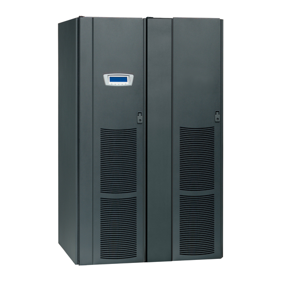
Eaton Powerware 9390 Installation And Operation Manual (218 pages)
Powerware Series 100–160 kVA
Brand:
Eaton
| Category:
UPS
| Size: 2 MB
Table of Contents
Important Safety Instructions
4
Save These Instructions
4
Special Symbols
5
Table of Contents
7
1 Introduction
13
Figure 1-1. Eaton 9390 UPS (100-160 Kva) Cabinet
13
UPS Standard Features
14
Control Panel
14
Customer Interface
14
X-Slot Communication Bay
14
Mini-CSB (Communication Server Board)
14
Connectups-X Web/Snmp Card X-Slot Card
14
Installation Features
15
Options and Accessories
15
Integrated Battery Cabinets
15
Integrated Accessory Cabinets (IAC-B, IAC-T, and IAC-D)
15
Powerware Hot Sync Parallel System
16
Sync Control
16
Optional X-Slot Cards
16
Remote Monitor Panel
16
Relay Interface Module
16
Supervisory Contact Module
16
Energy Saver and High Alert Modes
16
Basic System Configurations
17
Conventions Used in this Manual
18
For more Information
18
Getting Help
19
2 Safety Warnings
21
Section I - Installation
23
Eaton 9390 UPS (100-160 Kva) Installation and Operation Manual S 164201604 Rev E Www.eaton.com/Powerquality
24
3 UPS Installation Plan and Unpacking
25
Creating an Installation Plan
25
Preparing the Site
25
Environmental Considerations
25
Preparing for Wiring the UPS System
26
Inspecting and Unpacking the UPS Cabinet
26
Figure 3-1. Eaton 9390 UPS (100-160 Kva) Cabinet as Shipped on Pallet
26
15 Warranty
25
4 Installing the UPS System
29
Preliminary Installation Information
29
Unloading the UPS Cabinet from the Pallet and Mechanical Installation
30
Figure 4-1. Removing Front Shipping Bracket on the Eaton 9390 UPS
31
Figure 4-2. Removing Rear Shipping Bracket on the Eaton 9390 UPS
32
Battery Cabinet Installation
33
Integrated Distribution Cabinet Installation
33
Integrated Accessory Cabinet Installation
34
UPS Sidecar Wiring
34
Installing UPS External and Battery Power Wiring
34
External Wiring Installation Procedure a
35
External Wiring Installation Procedure B
36
Battery Wiring
38
Installing Interface Connections
38
TB1 and TB2 Connections
38
TB2 Battery Cabinet Connections
39
X-Slot Connections
40
Installing Accessories and Parallel System Control Wiring
41
Initial Startup
41
Completing the Installation Checklist
41
Installation Checklist
42
5 Installing a Remote Emergency Power-Off Control
45
REPO Installation
45
Figure 5-1. Eaton REPO Switch
45
Figure 5-2. REPO Wiring
46
6 Installing Optional Accessories
47
Installing a Powerware Hot Sync CAN Bridge Card
47
Figure 6-1. Powerware Hot Sync CAN Bridge Card
47
Installing Parallel System Control Wiring
48
Installing an RMP
49
Installing a RIM
50
Installing a SCM
52
Figure 6-2. Supervisory Contact Module TB2
53
Section II Operation
55
Eaton Powerware 9390 Installation And Operation Manual (226 pages)
100–160 kVA
Brand:
Eaton
| Category:
UPS
| Size: 4 MB
Table of Contents
Consignes de Sécurité
2
Important Safety Instructions
2
Table of Contents
3
1 Introduction
11
Basic System Configurations
12
Using this Manual
13
Appendix A - Installation Information
14
Conventions Used in this Manual
14
Warranty
14
Important Safety Instructions
15
Safety Warnings
15
For more Information
16
Getting Help
16
Section I - Installation
17
2 UPS Installation Plan and Unpacking
19
Creating an Installation Plan
19
Preparing the Site
19
Environmental Considerations
20
Preparing for Wiring the UPS System
20
Inspecting and Unpacking the UPS Cabinet
21
3 Installing the UPS System
23
Preliminary Installation Information
23
UPS Cabinet Installation
23
Unloading the Powerware 9390 UPS Cabinet from the Pallet
24
Front View
25
Battery Cabinet Installation
27
Installing UPS External and Battery Power Wiring
28
Integrated Accessory Cabinet Installation
28
Integrated Distribution Cabinet Installation
28
UPS Sidecar Wiring
28
External Wiring Installation Procedure a
29
External Wiring Installation Procedure B
31
Battery Wiring
32
Installing Interface Connections
33
TB1 and TB2 Connections
33
TB2 Battery Cabinet Connections
34
X-Slot Connections
35
Installing Accessories and Parallel System Control Wiring
36
Initial Startup
36
Completing the Installation Checklist
36
Installation Checklist
37
Parallel System Installation Checklist
38
4 Batteries
41
Important Safety Instructions
41
Installing Batteries
42
Recycling the Used Battery or UPS
42
5 Installing a Remote Emergency Power-Off Switch
43
6 Installing Options and Accessories
47
Installing a Powerware Hot Sync CAN Bridge Card
47
Installing Parallel System Control Wiring
48
Installing a Remote Monitor Panel
49
Installing a Relay Interface Module
50
Installing a Supervisory Contact Module
52
Section II - Operation
55
Eaton Powerware 9390 Installation And Operation Manual (226 pages)
Brand:
Eaton
| Category:
UPS
| Size: 4 MB
Table of Contents
Table of Contents
3
Introduction
11
Figure 1-1. Powerware 9390 UPS (100-160 Kva) Cabinet
11
Basic System Configurations
12
Using this Manual
13
Conventions Used in this Manual
14
Safety Warnings
15
For more Information
16
Getting Help
16
Section I - Installation
17
UPS Installation Plan and Unpacking
19
Creating an Installation Plan
19
Preparing the Site
19
Environmental Considerations
20
Preparing for Wiring the UPS System
20
Inspecting and Unpacking the UPS Cabinet
20
Figure 2-1. Powerware 9390 UPS (100-160 Kva) Cabinet as Shipped on Pallet
21
Installing the UPS System
23
Preliminary Installation Information
23
UPS Cabinet Installation
23
Unloading the Powerware 9390 UPS Cabinet from the Pallet
24
Figure 3-1. Removing Front Shipping Bracket on the Powerware 9390 UPS
25
Figure 3-2. Removing Rear Shipping Bracket on the Powerware 9390 UPS
26
Battery Cabinet Installation
27
Integrated Distribution Cabinet Installation
28
Integrated Accessory Cabinet Installation
28
UPS Sidecar Wiring
28
Installing UPS External and Battery Power Wiring
28
220V Input External Wiring Installation
29
Input External Wiring Installation
31
Battery Wiring
32
Installing Interface Connections
33
TB1 and TB2 Connections
33
TB1 Battery Cabinet Connections
34
X-Slot Connections
35
Installing Accessories and Parallel System Control Wiring
36
Initial Startup
36
Completing the Installation Checklist
36
Batteries
41
Important Safety Instructions
41
Installing Batteries
42
Recycling the Used Battery or UPS
42
Installing a Remote Emergency Power-Off Switch
43
Figure 5-1. REPO Switch
43
Installing Options and Accessories
47
Installing a Powerware Hot Sync CAN Bridge Card
47
Figure 6-1. Powerware Hot Sync CAN Bridge Card
47
Installing Parallel System Control Wiring
48
Installing a Remote Monitor Panel
49
Installing a Relay Interface Module
50
Installing a Supervisory Contact Module
52
Figure 6-2. Supervisory Contact Module II TB2
53
Section II - Operation
55
Understanding UPS Operation
57
Looking Inside the UPS System
57
Figure 7-1. Main Elements of the UPS System
57
Single Module Reverse Transfer (RT)
58
Single Module RT Modes
58
Normal Mode - RT
60
Figure 7-2. Path of Current through the UPS in Normal Mode - RT
60
Eaton Powerware 9390 Installation And Operation Manual (213 pages)
Brand:
Eaton
| Category:
UPS
| Size: 4 MB
Table of Contents
Table of Contents
9
Safety Warnings
24
UPS Installation Plan and Unpacking
27
Chapter 15 Installation Information
29
Integrated Distribution Cabinet (Distibuted Bypass) Installation
30
Installing UPS External and Battery Power Wiring
30
Installing the UPS System
31
Front View
31
Rear View
32
External Wiring Installation Procedure a
34
External Wiring Installation Procedure B
34
Battery Wiring
35
Chapter 14 Product Specifications
36
Installing Interface Connections
36
Chapter 9 UPS Operating Instructions
37
TB2 Battery Cabinet Connections
37
X-Slot Connections
38
Installing a Remote Emergency Power-Off Control
44
Installing an Eaton Hot Sync CAN Bridge Card
46
6.2 Installing Parallel System Control Wiring
46
Installing a Remote Monitor Panel (RMP)
46
Installing a Remote Interface Module (RIM)
46
Installing a Supervisory Contact Module (SCM)
46
Installing Optional Accessories
49
Chapter 14 Product
51
Understanding UPS Operation
52
Multiple Module UPS Distributed Bypass System
52
Single Module Reverse Transfer (RT)
52
Using the Control Panel
64
E Control Panel
67
Event Screens
68
System Unit
69
Battery - Unit
71
Active Events
75
Kw Demand Log
75
MIMIC Screen
77
System Meters
92
Total System
92
System Unit
93
Output Unit
94
Input Unit
95
Enter Password
99
Change Password
106
Com Port Setup
110
Com 1 Setup
111
Using the Control Panel
112
Chapter 9 UPS Operating
114
System Controls
114
Using Features and Options
134
Responding to System Events
140
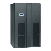
Eaton Powerware 9390 Installation And Operation Manual (124 pages)
Powerware Corporation Powerware 9390 UPS Sidecar Installation and Operation Manual
Brand:
Eaton
| Category:
UPS
| Size: 3 MB
Table of Contents
Consignes de Sécurité
2
Important Safety Instructions
2
Table of Contents
3
List of Figures
6
1 Introduction
7
Configurations
7
Figure 1-1. Powerware 9390 UPS (40-80 Kva) with UPS Sidecar
8
Figure 1-2. Powerware 9390 UPS (100-160 Kva) with UPS Sidecar
9
Using this Manual
10
5 Warranty
10
Conventions Used in this Manual
11
Safety Warnings
12
For more Information
12
Getting Help
13
6 Installation Information
10
Section I - Installation
15
2 Installing the UPS Sidecar
17
Installation Plan and Unpacking
17
Preliminary Installation Information
17
UPS Sidecar Installation - Maintenance Bypass Configuration
17
Installing the UPS Cabinet with UPS Sidecar
17
Installing Maintenance Bypass Power Wiring
17
Figure 2-1. 80 Kva UPS with UPS Sidecar
19
UPS Sidecar Installation - Parallel Redundant Configuration
20
Line-Up-And-Match Parallel Redundant Installation
20
Figure 2-2. Typical Line-Up-And-Match Parallel Redundant System (80 Kva System Shown)
20
Figure 2-3. UPM 1 to UPM 2 Joining Brackets
22
Installing Line-Up-And-Match Parallel Redundant Power Wiring
23
Standalone Parallel Redundant Installation
24
Figure 2-4. Typical Standalone Parallel Redundant System (80 Kva System Shown)
24
Installing Standalone Parallel Redundant Power Wiring
25
Installing UPS Sidecar TB1 Interface Connections
26
Initial Startup
26
Completing the Installation Checklist
26
Installation Checklist
27
Section II - Operation
29
3 Understanding Operation
31
Maintenance Bypass Configuration
31
UPS Mode
31
Figure 3-1. Path of Current through the UPS Sidecar in UPS Mode
31
Maintenance Bypass Mode with UPS Sidecar
32
Parallel Redundant Configuration
32
Figure 3-2. Path of Current through the UPS Sidecar in Maintenance Bypass Mode
32
4 UPS Sidecar Features, Controls, and Operation
33
UPS Sidecar Standard Features
33
Parallel Redundant Configuration
33
Customer Interface
33
Installation Features
33
Expansion
33
Options
33
Bypass Input Breaker (BIB)
33
Rectifier Input Breaker (RIB)
34
System Load Breaker (SLB)
34
Symbols
34
UPS Sidecar Controls
35
Figure 4-1. UPS Sidecar Controls (Bypass) - 40/20, 40/30, 40/40 Kva, 480/480V with MBP and MIS
36
Figure 4-2. UPS Sidecar Controls (Bypass) - 40/20, 40/30, 40/40 Kva, 480/480V with Optional BIB and RIB
37
Figure 4-3. UPS Sidecar Controls (Bypass) - 40/20, 40/30, 40/40 Kva, 208/208V and 80/40, 80/50, 80/60, 80/80 Kva and 120/100 and 120/120 Kva, 480/480V with MBP and MIS
38
Figure 4-4. UPS Sidecar Controls (Bypass) - 40/20, 40/30, 40/40 Kva, 208/208V and 80/40, 80/50, 80/60, 80/80 Kva and 120/100 and 120/120 Kva, 480/480V with Optional BIB and RIB
39
Figure 4-5. UPS Sidecar Controls (Bypass) - 80/40, 80/50, 80/60, 80/80 Kva, 208/208V and 160/100, 160/120, and 160/160 Kva, 480/480V with MBP and MIS
40
Figure 4-6. UPS Sidecar Controls (Bypass) - 80/40, 80/50, 80/60, 80/80 Kva, 208/208V and 160/100, 160/120, and 160/160 Kva, 480/480V with Optional BIB and RIB
41
Figure 4-7. UPS Sidecar Controls (Parallel Redundant) - 40/20, 40/30, 40/40 Kva, 480/480V with Mobs and Optional SLB
42
Figure 4-8. UPS Sidecar Controls (Parallel Redundant) - 40/20, 40/30, 40/40 Kva, 208/208V and
43
Figure 4-9. UPS Sidecar Controls (Parallel Redundant) - 80/40, 80/50, 80/60, 80/80 Kva, 208/208V
44
And 160/100, 160/120, and 160/160 Kva, 480/480V with Mobs and Optional SLB
44
Transferring the UPS to Maintenance Bypass
45
UPS Sidecar Operation – Maintenance Bypass Configuration
45
Using the UPS When a UPS Sidecar Is Installed
45
Transferring the UPS from Maintenance Bypass
46
UPS Sidecar Operation – Parallel Redundant Configuration
47
Maintaining the UPS Sidecar
47
Product Specifications
47
Limited Factory Warranty
49
Limitation of Liability
49
Other Limitations
49
Installation Information
51
Battery Cabinet
52
Physical Features and Requirements
55
Power Wiring Installation Notes
67
Bottom View
77
Top View
77
Inside Panel
79
Right Side View
79
Power Terminal Locations
80
Maintenance Bypass Configuration
88
Parallel Redundant Configuration
90
Front View
118
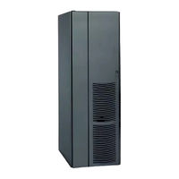
Eaton Powerware 9390 Installation And Operation Manual (100 pages)
40–80 kVA UPS, Integrated Distribution Cabinet
Brand:
Eaton
| Category:
UPS
| Size: 6 MB
Table of Contents
Table of Contents
3
Figure 1-1. the Eaton 9390 40-80 Kva IDC
7
IDC Features
8
Maintenance Bypass and Maintenance Isolation Breakers
8
Output Transformer
8
Installation Features
8
Expansion
8
IDC Options
8
Bypass Input Breaker
8
Rectifier Input Breaker
8
Distribution Panel
8
Distribution Breakers
8
Output Isolation Transformer
9
IDC Configurations
9
Safety Warnings
9
Conventions Used in this Manual
10
For more Information
11
Symbols, Controls and Indicators
11
Getting Help
12
Section 1 - Installation
13
2 IDC Installation Plan and Unpacking
15
Creating an Installation Plan
15
Preparing the Site
15
Environmental Considerations
15
Preparing for Wiring the IDC
15
Inspecting and Unpacking the IDC
16
Figure 2-1. Eaton 9390 40-80 Kva IDC as Shipped on Pallet
16
3 Installing the IDC
19
Preliminary Installation Information
19
Unloading the Cabinet from the Pallet
19
Figure 3-1. Removing the Front Shipping Bracket
20
Figure 3-2. Removing the Rear Shipping Bracket
21
IDC Installation
22
Line-Up-And-Match IDC Installation
22
Figure 3-3. UPS with Line-Up-And-Match IDC
22
Figure 3-4. IDC Knockout Plug and Hanger Bracket Locations
24
Figure 3-5. UPS to IDC Joining Brackets
25
Standalone IDC Installation
28
Figure 3-6. Eaton 9390 UPS with Standalone IDC
28
Initial Startup
30
Completing the Installation Checklist
30
Section 2 - Operation
33
4 Understanding IDC Operation
35
UPS Mode
35
Maintenance Bypass Mode
35
Figure 4-1. Path of Current through the IDC in UPS Mode
36
Figure 4-2. Path of Current through the IDC in Maintenance Bypass Mode
37
5 IDC Controls and Operation
39
IDC Controls
39
Figure 5-1. Eaton 9390 40-80 Kva IDC Controls - with Distribution Panel Option (208V)
40
Figure 5-2. Eaton 9390 40-80 Kva IDC Controls - with Distribution Breaker Option (208V)
41
Figure 5-3. Eaton 9390 40-80 Kva IDC Controls - with no Distribution (208V)
42
Figure 5-4. Eaton 9390 40-80 Kva IDC Controls - with Distribution Panel Option (480V)
43
Figure 5-5. Eaton 9390 40-80 Kva IDC Controls - with Distribution Breaker Option (480V)
44
Figure 5-6. Eaton 9390 40-80 Kva IDC Controls - with no Distribution (480V)
45
IDC Operation
46
Using the UPS When an IDC Is Installed
46
Transferring the UPS to Maintenance Bypass
46
Transferring the UPS from Maintenance Bypass
47
Using the Remote Emergency Power-Off (REPO) Switch
47
Figure 5-7. Eaton 9390 IDC Controls - Interlock Operation (208V)
48
Figure 5-8. Eaton 9390 IDC Controls - Interlock Operation (480V)
49
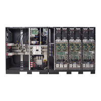
Eaton Powerware 9390 Installation And Operation Manual (96 pages)
Integrated Distribution Cabinet
Brand:
Eaton
| Category:
Power distribution unit
| Size: 4 MB
Table of Contents
Table of Contents
3
1 Introduction
7
Configurations
7
Figure 1-1. Powerware 9390 160 Kva IDC Cabinet
8
Installation Information
9
Using this Manual
9
Warranty
9
Conventions Used in this Manual
10
Safety Warnings
11
For more Information
12
Getting Help
12
Section I - Installation
13
2 IDC Installation Plan and Unpacking
15
Creating an Installation Plan
15
Preparing the Site
15
Environmental Considerations
16
Preparing for Wiring the IDC
16
Inspecting and Unpacking the IDC
16
3 Installing the IDC
19
Preliminary Installation Information
19
IDC Cabinet Installation
23
Figure 3-3. UPS with Integral IDC
23
Line-Up-And-Match IDC Installation
23
Figure 3-4. IDC Knockout Plug and Hanger Bracket Locations
25
Figure 3-5. UPS to IDC Joining Brackets
27
Installing IDC Line-Up-And-Match Power Wiring
28
Installing Line-Up-And-Match P1 and P2 Interface Connections
30
Figure 3-6. UPS with Standalone IDC
31
Standalone IDC Installation
31
Installing IDC Standalone Power Wiring
32
Installing Standalone P1 and P2 Interface Connections
34
Initial Startup
35
Completing the Installation Checklist
35
Section II - Operation
39
4 Understanding IDC Operation
41
UPS Mode
41
Maintenance Bypass Mode
41
Figure 4-1. Path of Current through the IDC in UPS Mode
42
Figure 4-2. Path of Current through the IDC in Maintenance Bypass Mode
43
5 IDC Features, Options, Controls, and Operation
45
IDC Standard Features
45
Customer Interface
45
Installation Features
45
Maintenance Bypass and Maintenance Isolation Switches
45
Output Transformer
45
Expansion
46
Options
46
Bypass Input Breaker (BIB)
46
Distribution Breakers
46
Distribution Panel
46
Lug Output
46
Rectifier Input Breaker (RIB)
46
Remote Emergency Power-Off
46
Symbols
47
IDC Controls
47
IDC Operation
51
Transferring the UPS to Maintenance Bypass
51
Using the UPS When an IDC Is Installed
51
Transferring the UPS from Maintenance Bypass
53
Using the Remote Emergency Power-Off Switch
54
6 Maintaining the IDC
57
Important Safety Instructions
57
Performing Preventive Maintenance
57
DAILY Maintenance
57
ANNUAL Maintenance
58
PERIODIC Maintenance
58
Short Circuits
58
Maintenance Training
58
7 Product Specifications
59
Model Number
59
IDC Input
59
IDC Output
59
Environmental Specifications
59
Installation Information
61
Front View
88
Eaton Powerware 9390 Installation And Operation Manual (130 pages)
40–80 kVA UPS Sidecar
Brand:
Eaton
| Category:
UPS
| Size: 3 MB
Table of Contents
List of Figures
14
Special Symbols
19
Chapter 5 Installation Information
21
Installing the UPS Sidecar
22
UPS Sidecar Features, Controls, and Operation
36
Battery Cabinet
50
Top View
75
Bottom View
75
Right Side View
77
Maintenance Bypass Configuration
86
Parallel Redundant Configuration
88
Top View
117
Bottom View
117
Eaton Powerware 9390 Manual (62 pages)
Brand:
Eaton
| Category:
UPS
| Size: 6 MB
Table of Contents
Table of Contents
4
Table 1. 9X55 Unit and Fastener Requirements from Unit to Floor
8
Table 2. 9X55 Unit Seismic Displacement Requirements
8
Table 3. 9X55 Unit Center of Gravity Specifications
9
Figure 1. 9X55 Stackable Unit Seismic Mounting Detail
10
Figure 2. 9X55 20-30 Kva Cabinet Seismic Mounting Detail
11
Table 4. 9390 Unit and Fastener Requirements from Unit to Floor
12
Table 5. 9390 Unit Seismic Displacement Requirements
12
Table 6. 9390 Unit Center of Gravity Specifications
13
Figure 3. 9390 80 Kva UPS Seismic Mounting Detail
14
Figure 4. 9390 160 Kva UPS Seismic Mounting Detail
15
Figure 5. 9390 20-80 Kva IDC Seismic Mounting Detail
16
Figure 6. 9390 20-80 Kva with Sidecar Seismic Mounting Dimensions
17
Figure 7. 9390 100-160 Kva with Sidecar Seismic Mounting Dimensions
17
Figure 8. 9390 160 Kva IDC Seismic Mounting Dimensions
18
Figure 9. 9390 80 Kva and 160 Kva IAC (B, D, & T)
19
Table 7. 9395/P/XC Unit and Fastener Requirements from Unit to Floor
20
Table 8. 9395/P/XC Unit Seismic Displacement Requirements
22
Table 9. 9395/P/XC Unit Center of Gravity Specifications
23
Figure 10. 9395 275 Kva or 9395P 300/600 UPS Seismic Mounting Dimensions
24
Figure 11. 9395 275 Kva or 9395P 300/600 Kva UPS and FI-UPM Seismic Mounting Dimensions
24
Figure 12. 9395 550 Kva or 9395P 600 Kva UPS Seismic Mounting Dimensions
25
Figure 13. 9395 550 Kva or 9395P 600 Kva UPS and FI-UPM Seismic Mounting Dimensions
25
Figure 14. 9395 825 Kva or 9395P 900 Kva UPS Seismic Mounting Dimensions
26
Figure 15. 9395 825 Kva UPS (2X-UPM) Seismic Mounting Dimensions
26
Figure 16. 9395 825 Kva or 9395P 900 Kva UPS (2X-UPM and FI-UPM) Seismic Mounting Dimensions
26
Figure 17. 9395 1100 Kva UPS or 825 Kva +1 or 9395P 1200 Kva UPS Seismic Mounting Dimensions
27
Figure 18. 9395 MBM Seismic Mounting Dimensions
27
Figure 19. 9395 MBM and 275 Kva UPS Seismic Mounting Dimensions
28
Figure 20. 9395 MBM and 550 Kva UPS Seismic Mounting Dimensions
28
Figure 21. 9395XC 1500 Kw (HD) UPS Seismic Mounting Dimensions
29
Figure 22. 9395XC 1500 Kw (LD) UPS Seismic Mounting Dimensions
29
Figure 23. 9395 Seismic Door Securing Hardware Detail
30
Figure 24. 9395 I/O Intercabinet Shim Location and Seismic Floor Bracket Attachment Detail
31
Figure 25. 9395 FI-UPM Shim Location Detail for Seismic Kit
32
Figure 26. 9395 Attachment Detail for FI-UPM and I/O Module
33
Table 10. 93PM Unit and Fastener Requirements from Unit to Floor
34
Table 11. 93PM Unit Seismic Displacement Requirements
35
Table 12. 93PM Unit Center of Gravity Specifications
36
Figure 27. 93PM-L UPS 60 and 120 Kw (208V) /93PM UPS 50, 100, and 150 Kw Frame (480V) Seismic Mounting Dimensions
39
Figure 28. 93PM-L UPS 60 Kw (208V) with Top Entry Sidecar /93PM UPS 50, 100, and 150 Kw Frame (480V) with
40
Figure 29. 93PM-L UPS 60 Kw with and 120 Kw (208V) with Large Sidecar
41
Figure 30. 93PM UPS 100 Kw and 150 Kw Frames with Large Sidecar (480V)
42
Figure 31. 93PM-L UPS 160 Kw (208V) Seismic Mounting Dimensions
43
Figure 32. 93PM-L UPS 200 Kw (208V) Seismic Mounting Dimensions
44
Figure 33. 93PM UPS (200 Kw Frame) Seismic Mounting Dimensions (480V)
45
Figure 34. 93PM UPS (200 Kw Frame with Sidecar) Seismic Mounting Dimensions (480V)
46
Figure 35. 93PM UPS (400 Kw Frame) Seismic Mounting Dimensions (480V)
47
Figure 36. 93PM-L (208V) and 93PM (480V) IAC-D Seismic Mounting Dimensions
48
Figure 37. 93PM (480V) IAC-T Seismic Mounting Dimensions
49
Eaton Powerware 9390 Installation Manuals (70 pages)
Powerware 9390 Integrated Battery Cabinet
Brand:
Eaton
| Category:
Enclosure
| Size: 1 MB
Table of Contents
Table of Contents
3
1 Introduction
7
Figure 1-1. Powerware 9390 Model IBC-S Battery Cabinet
7
Battery Cabinet Configurations
8
Figure 1-2. Powerware 9390 Model IBC-L Battery Cabinet
8
UPS Systems Using Powerware 9390 Battery Cabinets
8
Conventions Used in this Manual
9
Using this Manual
9
Safety Warnings
10
For more Information
11
Getting Help
12
2 Battery Cabinet Installation Plan and Unpacking
13
Installation Sequence
13
Creating an Installation Plan
13
Preparing the Site
13
Environment Considerations
14
Preparing for Wiring the Battery System
14
Inspecting and Unpacking the Battery Cabinet
15
Figure 2-1. Powerware 9390 Battery Cabinet as Shipped on Pallet (Model IBC-L Shown)
15
3 Installing Battery Cabinets
17
Preliminary Installation Information
17
Figure 3-1. Removing Shipping Supports
18
Unloading the Battery Cabinet from the Pallet
18
Model IBC-S Battery Cabinet Installation
20
Line-Up-And-Match IBC-S Installation
20
Figure 3-2. UPS with Line-Up-And-Match IBC-S
20
Figure 3-3. UPS to IBC-S Joining Brackets
21
Figure 3-4. IBC-S Bottom Joining Brackets and Ground Wire
22
Figure 3-5. IBC-S Hanger Brackets
23
Line-Up-And-Match IBC-S Electrical Connections
24
Figure 3-6. IBC-S Battery String Connection
25
Figure 3-7. UPS with Standalone IBC-S
26
Standalone IBC-S Installation
26
Standalone IBC-S Electrical Connections
28
Model IBC-L Battery Cabinet Installation
29
Figure 3-8. UPS with Line-Up-And-Match IBC-L
30
Figure 3-9. UPS to IBC-L Joining Brackets
31
Figure 3-10. IBC-L Bottom Joining Brackets and Ground Wire
32
Figure 3-11. IBC-L Battery Cabinet Hanger Brackets
33
Line-Up-And-Match IBC-L Electrical Connections
34
Figure 3-12. IBC-L Battery String Connection
35
Figure 3-13. UPS with Standalone IBC-L
36
Standalone IBC-L Installation
36
Standalone Battery Cabinet Electrical Connections
38
Completing the Installation Checklist
40
Eaton Powerware 9390 Installation And Operation Manual (48 pages)
Fixed Master Sync Control
Brand:
Eaton
| Category:
UPS
| Size: 0 MB
Table of Contents
Important Safety Instructions
2
Save These Instructions
2
Table of Contents
3
1 Introduction
5
Figure 1-1. Eaton Fixed Master Sync Control
5
Figure 1-2. Eaton Fixed Master Sync Control with Door Open
6
Figure 1-3. Eaton Sync Control Master Interface Panel
6
Conventions Used in this Manual
7
Safety Warnings
7
For more Information
8
Getting Help
8
2 Installation Plan and Unpacking
9
Creating an Installation Plan
9
Preparing the Site
9
Environmental and Installation Considerations
9
Figure 2-1. Eaton Fixed Master Sync Control Dimensions - Front View
10
Figure 2-2. Eaton Fixed Master Sync Control Dimensions - Side Views
11
Figure 2-3. Eaton Master Interface Enclosure Dimensions - Front View
12
Figure 2-4. Eaton Master Interface Enclosure Dimensions - Side. Rear, and Bottom Views
13
Eaton Fixed Master Sync Control and Master Interface Wiring Preparation
14
Inspecting and Unpacking the Eaton Fixed Master Sync Control or Master Interface
14
Figure 3-1. Fixed Master Sync Control with Master Interface Enclosure Functional Diagram
15
3 Installation
16
Figure 3-2. Typical Eaton Fixed Master Sync Control Control Wiring Termination Locations
16
Figure 3-3. Eaton Fixed Master Sync Control TB1 Terminal Block Detail
17
Figure 3-4. Typical Control Wiring Termination Locations for Eaton Master Interface Enclosure
18
Installation and Wiring with an Eaton 9315 UPS
19
Figure 3-5. TB6 Terminal Block Detail (All Systems)
24
Figure 3-6. Fixed Master Sync Control Interface Location for 30-80 Kva Single Module 9315 UPS System
24
Figure 3-7. Fixed Master Sync Control Interface Location for 100-160 Kva Single Module 9315 UPS System
25
Figure 3-8. Fixed Master Sync Control Interface Locations for 200-300 Kva Single Module 9315 UPS System
26
Figure 3-9. Fixed Master Sync Control Interface Location for 400-500 Kva Single Module 9315 UPS System
27
Figure 3-10. Fixed Master Sync Control Interface Location for 750 Kva Single Module 9315 UPS System
28
Installation and Wiring with an Eaton 9390 UPS
29
Figure 3-11. Eaton 9390 UPS (40-80 Kva) Interface Locations for Eaton Fixed Master Sync Control
31
Figure 3-12. Eaton 9390 UPS (100-160 Kva) Interface Locations for Eaton Fixed Master Sync Control
32
Figure 3-13. TB6 Terminal Block Detail
32
Installation and Wiring with an Power Xpert 9395 UPS
33
Figure 3-14. TB6 Terminal Block Detail (All Systems)
35
Figure 3-15. Power Xpert 9395 UPS (225-275 Kva) Interface Locations for Eaton Fixed Master Sync Control
35
Figure 3-16. Power Xpert 9395 UPS and Plus 1 UPS (450-550 Kva) Interface Locations for Eaton Fixed Master Sync Control
36
Figure 3-17. Power Xpert 9395 UPS and Plus 1 UPS (650-825 Kva) Interface Locations for Eaton Fixed Master Sync Control
37
Figure 3-18. Power Xpert 9395 UPS (1000-1100 Kva) Interface Locations for Eaton Fixed Master Sync Control
38
Figure 3-19. Relay Interface Card
39
Figure 3-20. Relay Interface Card Terminals
39
4 Operation
41
Startup for UPS Systems Equipped with an Eaton Fixed Master Sync Control
41
Understanding Eaton Fixed Master Sync Control Operation
41
Figure 4-1. Synchronization Reference Control
42
Operation
43
Figure 4-2. Eaton Fixed Master Sync Control Controls and Indicators
43
Maintenance Operations
44
5 Warranty
45
Eaton Powerware 9390 Installation And Operation Manual (50 pages)
Brand:
Eaton
| Category:
UPS
| Size: 2 MB
Table of Contents
Table of Contents
9
List of Figures
12
1 Introduction
13
Figure 1-1. Eaton Sync Control
13
Conventions Used in this Manual
14
Figure 1-2. Eaton Sync Control with Door Open
14
Safety Warnings
15
For more Information
16
Getting Help
16
Warranty
16
2 Installation Plan and Unpacking
17
Creating an Installation Plan
17
Preparing the Site
17
Environmental and Installation Considerations
17
Figure 2-1. Eaton Sync Control Dimensions - Front View
18
Figure 2-2. Eaton Sync Control Dimensions - Side Views
19
Eaton Sync Control and Primary Interface Wiring Preparation
20
Inspecting and Unpacking the Eaton Sync Control or Primary Interface
20
3 Installation
21
Installation and Wiring with an Eaton 9390 UPS
21
Figure 3-1. Typical Eaton Sync Control Wiring Terminal Locations
22
Figure 3-2. Eaton Sync Control TB1 Terminal Block Detail
24
Figure 3-3. Eaton 9390 UPS (40-80 Kva) Interface Locations for Eaton Sync Control
25
Figure 3-4. Eaton 9390 UPS (100-160 Kva) Interface Locations for Eaton Sync Control
26
Figure 3-5. TB6 Terminal Block Detail
27
Figure 3-6. Mini CSB Interface Terminals
27
Installation and Wiring with an Eaton 9395 UPS
28
Figure 3-7. Eaton 9395 UPS (225-275 Kva) Interface Locations for Eaton Sync Control
30
Figure 3-8. Eaton 9395 UPS and Plus 1 UPS (450-550 Kva) Interface Locations for Eaton Sync Control
31
Figure 3-9. Eaton 9395 UPS and Plus 1 UPS (650-825 Kva) Interface Locations for Eaton Sync Control
32
Figure 3-10. Eaton 9395 UPS (1000-1100 Kva) Interface Locations for Eaton Sync Control
33
Figure 3-11. Relay Interface Card End View
34
Figure 3-12. Relay Interface Card Terminals
34
Figure 3-13. Industrial Relay Card
35
Installation and Wiring with an Eaton 9395 SBM
36
Figure 3-14. SBM Control Pan Interface Terminal Locations
38
Figure 3-15. TB1 and TB2 Interface Terminal Detail
39
Figure 3-16. TB4 and TB5 Interface Terminal Detail
39
Figure 3-17. Terminal Block TB2 Connector Assignments
40
Figure 3-18. Terminal Block TB3 Connector Assignments
40
Figure 3-19. SBM to UPS Interconnection System Control Wiring
41
4 Operation
43
Startup for UPS Systems Equipped with an Eaton Sync Control
43
Understanding Eaton Sync Control Operation
43
Figure 4-1. Typical Eaton Sync Control Block Diagram with a Eaton 9390 UPS, Eaton 9395 UPS, or 9395 SSBM
44
Figure 4-2. Synchronization Reference Control
45
Figure 4-3. Eaton Sync Control Controls and Indicators
46
Maintenance Operations
47
Eaton Powerware 9390 Installation And Operation Manual (47 pages)
Brand:
Eaton
| Category:
UPS
| Size: 1 MB
Table of Contents
Table of Contents
6
Introduction
8
Figure 1-1. Eaton Sync Control
8
Conventions Used in this Manual
9
Figure 1-2. Eaton Sync Control with Door Open
9
Safety Warnings
10
For more Information
11
Getting Help
11
Installation Plan and Unpacking
12
Creating an Installation Plan
12
Preparing the Site
12
Environmental and Installation Considerations
12
Figure 2-1. Eaton Sync Control Dimensions - Front View
13
Figure 2-2. Eaton Sync Control Dimensions - Side Views
14
Eaton Sync Control Wiring Preparation
15
Inspecting and Unpacking the Eaton Sync Control
15
Installation
16
Installation and Wiring with an Eaton 9390 UPS
16
Figure 3-1. Typical Eaton Sync Control Wiring Terminal Locations
17
Figure 3-2. Eaton Sync Control TB1 Terminal Block Detail
19
Figure 3-3. Eaton 9390 UPS (40-80 Kva) Interface Locations for Eaton Sync Control
20
Figure 3-4. Eaton 9390 UPS (100-160 Kva) Interface Locations for Eaton Sync Control
21
Figure 3-5. TB6 Terminal Block Detail
22
Figure 3-6. Mini CSB Interface Terminals
22
Installation and Wiring with an Eaton 9395 UPS
23
Figure 3-7. Eaton 9395 UPS (225-275 Kva) Interface Locations for Eaton Sync Control
25
Figure 3-8. Eaton 9395 UPS and Plus 1 UPS (450-550 Kva) Interface Locations for Eaton Sync Control
26
Figure 3-9. Eaton 9395 UPS and Plus 1 UPS (650-825 Kva) Interface Locations for Eaton Sync Control
27
Figure 3-10. Eaton 9395 UPS (1000-1100 Kva) Interface Locations for Eaton Sync Control
28
Installation and Wiring with an Eaton 9395 SBM
31
Figure 3-14. SBM Control Pan Interface Terminal Locations
33
Figure 3-15. TB1 and TB2 Interface Terminal Detail
34
Figure 3-16. TB4 and TB5 Interface Terminal Detail
34
Figure 3-17. Terminal Block TB2 Connector Assignments
35
Figure 3-18. Terminal Block TB3 Connector Assignments
35
Figure 3-19. SBM to UPS Interconnection System Control Wiring
36
Operating Instructions
38
Startup for UPS Systems Equipped with an Eaton Sync Control
38
Understanding Eaton Sync Control Operation
38
Figure 4-1. Typical Eaton Sync Control Block Diagram with a Eaton 9390 UPS, Eaton 9395 UPS, or 9395 SSBM
39
Operation
40
Figure 4-2. Synchronization Reference Control
40
Figure 4-3. Eaton Sync Control Controls and Indicators
41
Maintenance Operations
42
Warranty
44
Eaton Powerware 9390 Installation And Operation Manual (46 pages)
Brand:
Eaton
| Category:
Control Unit
| Size: 1 MB
Table of Contents
Table of Contents
5
Introduction
7
Figure 1-1. Eaton Sync Control
7
Conventions Used in this Manual
8
Figure 1-2. Eaton Sync Control with Door Open
8
Safety Warnings
9
For more Information
10
Getting Help
10
Installation Plan and Unpacking
11
Creating an Installation Plan
11
Preparing the Site
11
Environmental and Installation Considerations
11
Figure 2-1. Eaton Sync Control Dimensions - Front View
12
Figure 2-2. Eaton Sync Control Dimensions - Side Views
13
Eaton Sync Control Wiring Preparation
14
Inspecting and Unpacking the Eaton Sync Control
14
Installation
15
Installation and Wiring with an Eaton 9390 UPS
15
Figure 3-1. Typical Eaton Sync Control Wiring Terminal Locations
16
Figure 3-2. Eaton Sync Control TB1 Terminal Block Detail
18
Figure 3-3. Eaton 9390 UPS (40-80 Kva) Interface Locations for Eaton Sync Control
19
Figure 3-4. Eaton 9390 UPS (100-160 Kva) Interface Locations for Eaton Sync Control
20
Figure 3-5. TB6 Terminal Block Detail
21
Figure 3-6. Mini CSB Interface Terminals
21
Installation and Wiring with an Eaton 9395 UPS
22
Figure 3-7. Eaton 9395 UPS (225-275 Kva) Interface Locations for Eaton Sync Control
24
Figure 3-8. Eaton 9395 UPS and Plus 1 UPS (450-550 Kva) Interface Locations for Eaton Sync Control
25
Figure 3-9. Eaton 9395 UPS and Plus 1 UPS (650-825 Kva) Interface Locations for Eaton Sync Control
26
Figure 3-10. Eaton 9395 UPS (1000-1100 Kva) Interface Locations for Eaton Sync Control
27
Installation and Wiring with an Eaton 9395 SBM
30
Figure 3-14. SBM Control Pan Interface Terminal Locations
32
Figure 3-15. TB1 and TB2 Interface Terminal Detail
33
Figure 3-16. TB4 and TB5 Interface Terminal Detail
33
Figure 3-17. Terminal Block TB2 Connector Assignments
34
Figure 3-18. Terminal Block TB3 Connector Assignments
34
Figure 3-19. SBM to UPS Interconnection System Control Wiring
35
Operating Instructions
37
Startup for UPS Systems Equipped with an Eaton Sync Control
37
Understanding Eaton Sync Control Operation
37
Figure 4-1. Typical Eaton Sync Control Block Diagram with a Eaton 9390 UPS, Eaton 9395 UPS, or 9395 SSBM
38
Operation
39
Figure 4-2. Synchronization Reference Control
39
Figure 4-3. Eaton Sync Control Controls and Indicators
40
Maintenance Operations
41
Warranty
43
Eaton Powerware 9390 Installation And Operation Manual (36 pages)
Sync Control
Brand:
Eaton
| Category:
UPS
| Size: 0 MB
Table of Contents
Important Safety Instructions
2
Save These Instructions
2
Table of Contents
3
1 Introduction
5
Figure 1-1. Powerware Sync Control
5
Conventions Used in this Manual
6
Figure 1-2. Powerware Sync Control with Door Open
6
Safety Warnings
7
For more Information
8
Getting Help
8
2 Installation Plan and Unpacking
9
Creating an Installation Plan
9
Preparing the Site
9
Environmental and Installation Considerations
9
Figure 2-1. Powerware Sync Control Dimensions - Front View
10
Figure 2-2. Powerware Sync Control Dimensions - Side Views
11
Powerware Sync Control Wiring Preparation
12
Inspecting and Unpacking the Powerware Sync Control
12
3 Powerware Sync Control Installation
13
Installation and Wiring with a Powerware 9390 UPS
13
Figure 3-1. Powerware Sync Control Typical Control Wiring Termination Locations
15
Figure 3-2. Powerware Sync Control TB1 Terminal Block Detail
16
Figure 3-3. Powerware 9390 UPS (40-80 Kva) Interface Locations for Powerware Sync Control
17
Figure 3-4. Powerware 9390 UPS (100-160 Kva) Interface Locations for Powerware Sync Control
18
Figure 3-5. TB6 Terminal Block Detail
18
Installation and Wiring with a Powerware 9395 UPS
19
Figure 3-6. Powerware 9395 UPS (225-275 Kva) Interface Locations for Powerware Sync Control
21
Figure 3-7. Powerware 9395 UPS and Plus 1 UPS (450-550 Kva) Interface Locations for Powerware Sync Control
22
Figure 3-8. Powerware 9395 UPS and Plus 1 UPS (650-825 Kva) Interface Locations for Powerware Sync Control
23
Figure 3-9. Powerware 9395 UPS (1000-1100 Kva) Interface Locations for Powerware Sync Control
24
Figure 3-10. Relay Interface Card
25
Figure 3-11. Relay Interface Card Terminals
25
4 Powerware Sync Control Operating Instructions
27
Startup for UPS Systems Equipped with a Powerware Sync Control
27
Understanding Powerware Sync Control Operation
27
Figure 4-1. Typical Powerware Sync Control Block Diagram with a Powerware 9390 or Powerware 9395 UPS System
28
Operation
29
Figure 4-2. Synchronization Reference Control
29
Figure 4-3. Powerware Sync Control Controls and Indicators
30
Customer Monitoring
31
Maintenance Operations
31
5 Warranty
33
Eaton Powerware 9390 Brochure & Specs (20 pages)
20-160 KVA
Brand:
Eaton
| Category:
UPS
| Size: 1 MB
Table of Contents
Power Conditioner
10
Frequency Converter
10
Battery Cabinet
11
Power Distribution Unit (PDU)
16
Technical Specifications
20
Eaton Powerware 9390 Specifications Manual (16 pages)
Static 20-160 kVa
Brand:
Eaton
| Category:
UPS
| Size: 0 MB
Table of Contents
Environmental Requirements
3
Mechanical Design
11
Controls and Indicators
12
Installation
15
Warranty
16
Eaton Powerware 9390 Brochure & Specs (7 pages)
40 - 160 kVA
Brand:
Eaton
| Category:
UPS
| Size: 0 MB
Advertisement
Related Products
Eaton 9108-22
Eaton Powerware 225 kVA Three-Phase Power Distribution Unit
Eaton Powerware 9390 UPS Sidecar
Eaton Powerware 9390 IAC-D
Eaton Powerware 9390 IAC-B
Eaton Powerware 9390 IAC-T
Eaton 9390P
Eaton 9390IT
Eaton Powerware 9390-120/100
Eaton Powerware 9390-120/120
Eaton Categories
UPS
Circuit breakers
Switch
Industrial Equipment
Industrial Electrical
More Eaton Manuals
Login
Sign In
OR
Sign in with Facebook
Sign in with Google
Upload manual
Upload from disk
Upload from URL