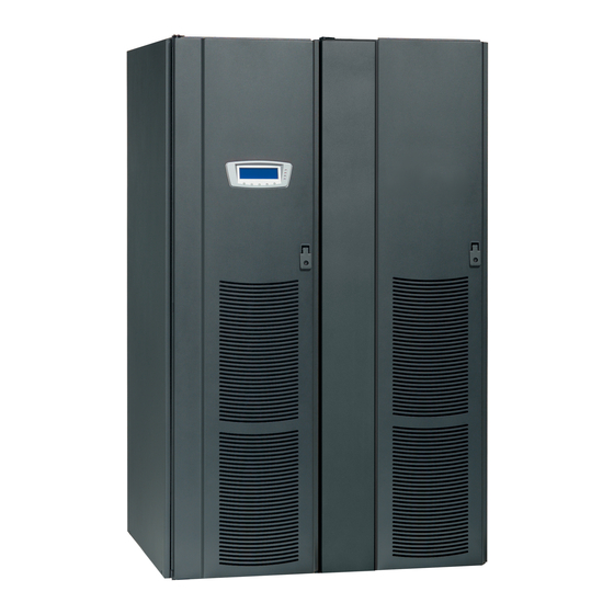
Eaton Powerware 9390 Installation And Operation Manual
100-160 kva
Hide thumbs
Also See for Powerware 9390:
- Installation and operation manual (232 pages) ,
- Brochure & specs (20 pages) ,
- Specifications manual (16 pages)
Table of Contents
Advertisement
Quick Links
Advertisement
Table of Contents

Related Manuals for Eaton Powerware 9390


Summary of Contents for Eaton Powerware 9390
-
Page 2: Important Safety Instructions
Powerware, X-Slot, and ABM are registered trademarks and ConnectUPS is a trademark of Eaton Electrical Inc. Modbus is a registered trademark of Modicon. IBM and AS/400 are registered trademarks of International Business Machines Corp. -
Page 3: Table Of Contents
........... . 3.2.1 Unloading the Powerware 9390 UPS Cabinet from the Pallet .... - Page 4 Table of Contents 4 Batteries ............. . . Important Safety Instructions .
- Page 5 Table of Contents 8 Features, Options, and Accessories ........UPS Standard Features .
- Page 6 Table of Contents System Controls Screen ........... . 9-45 Load Off Screen .
- Page 7 Table of Contents 13 Communication ............13-1 13.1 X-Slot Cards .
- Page 8 Table of Contents This page intentionally left blank. EATON Powerware 9390 UPS (100–160 kVA) Installation and Operation Manual S 164201554 Rev E powerware.com ®...
- Page 9 ........Figure 2-1. Powerware 9390 UPS (100–160 kVA) Cabinet as Shipped on Pallet .
- Page 10 List of Figures Figure 9-24. Maximum Current Log Setup Screen 1 ........9-21 Figure 9-25.
-
Page 11: Introduction
AC power to protect the customer’s load from all nine power failures. The Powerware 9390 UPS is available as a single module or a multiple module parallel system (see paragraph 1.1). -
Page 12: Basic System Configurations
Introduction 1.1 Basic System Configurations The following basic UPS system configurations are possible: Single module UPS and one to four battery cabinets Single module UPS with UPS Sidecar (maintenance bypass or 1+1 tie configuration) and one to four battery cabinets Single module UPS, one to four battery cabinets, and an optional Integrated Distribution Cabinet (IDC) Single module UPS, one to four battery cabinets, and an optional Integrated Accessory... -
Page 13: Using This Manual
Introduction 1.2 Using This Manual This manual describes how to install and operate the Powerware 9390 UPS (100–160 kVA) cabinet. Read and understand the procedures described in this manual to ensure trouble-free installation and operation. In particular, be thoroughly familiar with the REPO procedure (see page 10-7). -
Page 14: Conventions Used In This Manual
Introduction contains maintenance instructions for the Chapter 14, “Maintaining the UPS System” – UPS system. provides detailed specifications for the UPS Chapter 15, “Product Specifications” – system. contains important information on wiring Appendix A, “Installation Information” – requirements and recommendations, and important diagrams of the cabinets’ mechanical details and electrical access. -
Page 15: Safety Warnings
Introduction 1.4 Safety Warnings IMPORTANT SAFETY INSTRUCTIONS SAVE THESE INSTRUCTIONS This manual contains important instructions that should be followed during installation and maintenance of the UPS and batteries. Please read all instructions before operating the equipment and save this manual for future reference. The UPS cabinet is designed for industrial or computer room applications, and contains safety UPS system shields behind the doors. -
Page 16: For More Information
Introduction 1.5 For More Information Refer to the Powerware 9390 Integrated Battery Cabinet (Models IBC-S and IBC-L) Installation Manual (164201536) for the following additional information: Integrated Battery Cabinet (IBC) installation instructions, including site preparation, planning for installation, wiring, and safety information. -
Page 17: Section I - Installation
Section I Installation EATON Powerware 9390 UPS (100–160 kVA) Installation and Operation Manual S 164201554 Rev E powerware.com ®... - Page 18 This page intentionally left blank. EATON Powerware 9390 UPS (100–160 kVA) Installation and Operation Manual S 164201554 Rev E powerware.com ®...
-
Page 19: Ups Installation Plan And Unpacking
Chapter 2 UPS Installation Plan and Unpacking Use the following basic sequence of steps to install the UPS: 1. Create an installation plan for the UPS system (Chapter 2). 2. Prepare your site for the UPS system (Chapter 2). 3. Inspect and unpack the UPS cabinet (Chapter 2). 4. -
Page 20: Environmental Considerations
UPS Installation Plan and Unpacking 2.2.1 Environmental Considerations The life of the UPS system is adversely affected if the installation does not meet the following guidelines: The system must be installed on a level floor suitable for computer or electronic equipment. -
Page 21: Figure 2-1. Powerware 9390 Ups (100-160 Kva) Cabinet As Shipped On Pallet
UPS Installation Plan and Unpacking Figure 2-1. Powerware 9390 UPS (100–160 kVA) Cabinet as Shipped on Pallet C A U T I O N The UPS cabinet is heavy (see Table A on page A-3). If unpacking instructions are not closely followed, the cabinet may tip and cause serious injury. - Page 22 UPS Installation Plan and Unpacking 3. Set the pallet on a firm, level surface, allowing a minimum clearance of 3m (10 ft) on each side for removing the cabinet from the pallet. NOTE The UPS cabinet is shipped with a debris shield covering the ventilation grill on top of the unit.
-
Page 23: Installing The Ups System
Chapter 3 Installing the UPS System 3.1 Preliminary Installation Information W A R N I N G Installation should be performed only by qualified personnel. Refer to the following while installing the UPS system: Appendix A contains installation drawings and additional installation notes. Dimensions are in millimeters and inches. -
Page 24: Unloading The Powerware 9390 Ups Cabinet From The Pallet
Installing the UPS System 3.2.1 Unloading the Powerware 9390 UPS Cabinet from the Pallet The UPS cabinet is bolted to a wooden pallet supported by wood skids. To remove the pallet, perform the following procedure: W A R N I N G The UPS cabinet is heavy. -
Page 25: Figure 3-1. Removing Front Shipping Bracket On The Powerware 9390 Ups
Skid Bolts Shipping Bracket Bolts Pallet Shipping Bracket Bolts Removable Skid Front Shipping Bracket Figure 3-1. Removing Front Shipping Bracket on the Powerware 9390 UPS EATON Powerware 9390 UPS (100–160 kVA) Installation and Operation Manual S 164201554 Rev E powerware.com ®... -
Page 26: Figure 3-2. Removing Rear Shipping Bracket On The Powerware 9390 Ups
Installing the UPS System Rear View Shipping Bracket Bolts Pallet Shipping Bracket Bolts Rear Shipping Bracket Figure 3-2. Removing Rear Shipping Bracket on the Powerware 9390 UPS EATON Powerware 9390 UPS (100–160 kVA) Installation and Operation Manual S 164201554 Rev E powerware.com ®... -
Page 27: Battery Cabinet Installation
3.2.3; otherwise, proceed to paragraph 3.2.6. 3.2.2 Battery Cabinet Installation To install the battery cabinet, refer to the Powerware 9390 Integrated Battery Cabinet (Models IBC-S and IBC-L) Installation Manual. After the battery cabinet is installed, return to paragraph 3.2.6 to wire the UPS and battery cabinet. -
Page 28: Integrated Distribution Cabinet Installation
3.2.6 to complete the UPS cabinet wiring. 3.2.4 Integrated Accessory Cabinet Installation To install and wire an IAC, refer to the Powerware 9390 Integrated Accessory Cabinet (IAC-B and IAC-T Configurations) Installation and Operation Manual or the Powerware 9390 Integrated Accessory Cabinet (IAC-D Configuration) Installation and Operation Manual. -
Page 29: 220V Input External Wiring Installation
Installing the UPS System C A U T I O N DELTA SOURCES (TN-S) - The 9390 UPS system can be operated only from a delta supply source that is fully floating and if the neutral-forming transformer kit (PN 103005400) is installed in the UPS. - Page 30 Installing the UPS System C A U T I O N In the following step, DO NOT move the sensing and EMI wires from the rectifier contactor K1 input terminals. These wires must remain connected to the K1 terminals for proper UPS operation.
-
Page 31: Input External Wiring Installation
Installing the UPS System 3.2.6.2 480V Input External Wiring Installation To install wiring to connections: 1. Slide the air filters up and remove them from the cabinet. 2. Remove the screws securing the control panel door and swing the door open. Retain the hardware for later use. -
Page 32: Battery Wiring
To install wiring to connections: 1. Route and connect the battery cables between the UPS and battery cabinets in accordance with the instructions in the Powerware 9390 Integrated Battery Cabinet (Models IBC-S and IBC-L) Installation Manual. See Appendix A for UPS cabinet wiring access information. -
Page 33: Installing Interface Connections
Installing the UPS System 4. If wiring interface connections, proceed to paragraph 3.2.7; otherwise, proceed to Step 5. 5. When all wiring is complete, reinstall the safety shield panels removed in previous steps. Secure with the retained hardware. 6. Close the control panel door and secure with the retained hardware. 7. -
Page 34: Tb1 Battery Cabinet Connections
Installing the UPS System 11. Route and connect the wiring. 12. If wiring TB1 battery cabinet interface connections, proceed to paragraph 3.2.7.2; if wiring the X-Slot connections only, proceed to paragraph 3.2.7.3; otherwise, proceed to Step 13. 13. When all wiring is complete, reinstall the safety shield panels removed in previous steps. -
Page 35: X-Slot Connections
Installing the UPS System 12. Remove the screws securing the bottom and right side internal safety shield panels and remove the panels to gain access to the bottom conduit landing plate. NOTE When installing UV trip and Aux battery interface wiring to the UPS interface terminals, conduit must be installed between the UPS and battery cabinets. -
Page 36: Installing Accessories And Parallel System Control Wiring
Installing the UPS System 6. When all wiring is complete, reinstall the safety shield panels removed in previous steps. Secure with the retained hardware. 7. Close the control panel door and secure with the retained hardware. 8. Reinstall the doors removed previously and secure with the retained hardware. 9. -
Page 37: Installation Checklist
Installing the UPS System Installation Checklist - All packing materials and restraints have been removed from each cabinet. - Each cabinet in the UPS system is placed in its installed location. - The front shipping bracket is installed and adjusted, if the cabinet is not installed permanently. - A cabinet grounding/mounting kit is installed between any cabinets that are bolted together. - Page 38 Installing the UPS System Parallel System Installation Checklist - Each cabinet in the parallel system is placed in its installed location. - All conduits and cables are properly routed to the UPMs and to the parallel tie or distribution cabinet. - All power cables are properly sized and terminated.
- Page 39 Installing the UPS System Notes _________________________________________________________________________ _________________________________________________________________________ _________________________________________________________________________ _________________________________________________________________________ _________________________________________________________________________ _________________________________________________________________________ _________________________________________________________________________ _________________________________________________________________________ _________________________________________________________________________ _________________________________________________________________________ _________________________________________________________________________ _________________________________________________________________________ _________________________________________________________________________ _________________________________________________________________________ _________________________________________________________________________ _________________________________________________________________________ 3-17 EATON Powerware 9390 UPS (100–160 kVA) Installation and Operation Manual S 164201554 Rev E powerware.com ®...
- Page 40 Installing the UPS System This page intentionally left blank. 3-18 EATON Powerware 9390 UPS (100–160 kVA) Installation and Operation Manual S 164201554 Rev E powerware.com ®...
-
Page 41: Batteries
Chapter 4 Batteries 4.1 Important Safety Instructions This chapter describes installing the UPS batteries. C A U T I O N Only qualified service personnel (such as a licensed electrician) should perform the battery installation. Risk of electrical shock. DO NOT DISCONNECT the batteries while the UPS is in Battery mode. NOTE Consider all warnings, cautions, and notes before installing or replacing batteries. -
Page 42: Installing Batteries
Batteries A V E R T I S S E M E N T ! Les batteries peuvent présenter un risque de décharge électrique ou de brûlure par des courts-circuits de haute intensité. Prendre les précautions nécessaires. Pour le replacement, utiliser le même nombre et modéle des batteries. A T T E N T I O N ! Une mise au rebut réglementaire des batteries est obligatoire. -
Page 43: Installing A Remote Emergency Power-Off Switch
Chapter 5 Installing a Remote Emergency Power-off Switch A latching-type REPO switch can be used in an emergency to shut down the UPS and remove power to the critical load from a location away from where the UPS is installed. Figure 5-1 shows a REPO switch. - Page 44 Installing a Remote Emergency Power-off Switch 6. Remove the screws securing the internal panel covering the TB1 and TB2 terminal blocks at the top of the UPS cabinet (see Drawing 164201554-8 starting on page A-33). 7. If installing interface wiring from the bottom of the cabinet, proceed to Step 8; otherwise, proceed to Step 10.
- Page 45 Installing a Remote Emergency Power-off Switch 13. If you are installing multiple REPO stations, wire additional stations in parallel with the first REPO. 14. If required, install wiring from the REPO station to trip circuitry of upstream protective devices. A normally-open (NO) contact is provided between terminals 6 and 7 of REPO, as shown in Figure 5-1.
- Page 46 Installing a Remote Emergency Power-off Switch This page intentionally left blank. EATON Powerware 9390 UPS (100–160 kVA) Installation and Operation Manual S 164201554 Rev E powerware.com ®...
-
Page 47: Installing Options And Accessories
Chapter 6 Installing Options and Accessories 6.1 Installing a Powerware Hot Sync CAN Bridge Card As an option, a Powerware Hot Sync Computer Area Network Bridge Card shown in Figure 6-1, can be installed to provide connectivity for operational mode control and metering of a parallel system at any UPM in the system. -
Page 48: Installing Parallel System Control Wiring
Installing Options and Accessories 4. Install wiring from the Powerware Hot Sync CAN Bridge Card in accordance with the instructions listed below: Parallel system wiring (see paragraph 6.2) RMP II wiring (see paragraph 6.3) RIM II (see paragraph 6.4) SCM II (see paragraph 6.5) 6.2 Installing Parallel System Control Wiring When installing external wiring to the X-Slot CAN card, conduit must be NOTE... -
Page 49: Installing A Remote Monitor Panel
Installing Options and Accessories 11. Install parallel system backup control (pull chain) wiring between UPMs. See Drawing 164201554-8 starting on page A-33 for terminal locations and wiring information. 12. Install parallel system backup control (pull chain) wiring between the bypass relay and building alarm 2. -
Page 50: Installing A Relay Interface Module
Installing Options and Accessories 7. Install wiring between the UPS and RMP II. See Drawing 164201554-8 starting on page A-33 for Powerware Hot Sync CAN Bridge Card and RMP II location, terminal location, and wiring information. 120 Vac for the RMP II should be supplied from the critical bus by facility NOTE planners or the customer. - Page 51 Installing Options and Accessories When installing signal wiring for CAN card J3 terminals, conduit must be NOTE installed between the device and the UPS cabinet. Remove the UPS cabinet top or bottom conduit landing plate to drill or punch NOTE conduit holes (see Drawing 164201554-6 on page A-27).
-
Page 52: Installing A Supervisory Contact Module
Installing Options and Accessories 6.5 Installing a Supervisory Contact Module II To install SCM II wiring, perform the following procedure: 1. Verify the UPS system is turned off and all power sources are removed. See Chapter 10, “UPS Operating Instructions,” for shutdown instructions. 2. -
Page 53: Figure 6-2. Supervisory Contact Module Ii Tb2
Installing Options and Accessories 9. Install wiring between the SCM II terminal block TB2 and the monitoring equipment. See Figure 6-2 for terminal assignments and Drawing 164201554-8 on page A-33 for terminal block location. System Normal No Redundancy On Generator Bypass Not Available On Battery... - Page 54 Installing Options and Accessories This page intentionally left blank. EATON Powerware 9390 UPS (100–160 kVA) Installation and Operation Manual S 164201554 Rev E powerware.com ®...
-
Page 55: Section Ii - Operation
Section II Operation EATON Powerware 9390 UPS (100–160 kVA) Installation and Operation Manual S 164201554 Rev E powerware.com ®... - Page 56 This page intentionally left blank. 6-10 EATON Powerware 9390 UPS (100–160 kVA) Installation and Operation Manual S 164201554 Rev E powerware.com ®...
-
Page 57: Understanding Ups Operation
Understanding UPS Operation 7.1 Looking Inside the UPS System The Powerware 9390 UPS is a continuous-duty, solid-state, transformerless (at 208 and 480 Vac), three-phase, true online system that provides conditioned and uninterruptible AC power to the UPS system’s output. The UPS supports process control, data processing, telecommunications/PBX, research, and non-patient medical equipment. -
Page 58: Single Module Reverse Transfer (Rt)
7.2.1 Single Module RT Modes The Powerware 9390 UPS supports a critical load in three different modes of operation. The UPS can automatically use all three modes, as required. The standard operation... - Page 59 Understanding UPS Operation The UPS continually monitors itself and the incoming utility power, and automatically switches between these modes as required, without operator intervention. The sophisticated detection and switching logic inside the UPS ensures that operating mode changes are automatic and transparent to the critical load, while internal monitoring systems indicate the current mode of operation.
-
Page 60: Normal Mode - Rt
Understanding UPS Operation 7.2.2 Normal Mode – RT Figure 7-2 shows the path of electrical power through the UPS system when the UPS is operating in Normal mode. Static Static Switch Switch Rectifier Rectifier Inverter Inverter Battery Battery Converter Converter Main Power Flow Main Power Flow Breakers Contactors... - Page 61 Understanding UPS Operation The neutral from the system input is connected to the neutral regulator in the DC capacitors. The output neutral of the system is connected with the required neutral supplied at the utility bypass input and should never be bonded to ground at the module’s output.
-
Page 62: Figure 7-3. Path Of Current Through The Ups In Bypass Mode - Rt
Understanding UPS Operation 7.2.3 Bypass Mode – RT The UPS automatically switches to Bypass mode if it detects an overload, load fault, or internal failure. The bypass source supplies the commercial AC power to the load directly. Figure 7-3 shows the path of electrical power through the UPS system when operating in Bypass mode. - Page 63 Understanding UPS Operation During an outage, the UPS prohibits transfers to bypass and provides upstream protection. The backfeed protection contactor is opened, preventing system output voltage from bleeding across the static switch snubber components to the bypass input source. To ensure the load remains energized, the UPS automatically transfers the output to the internal bypass when one of these abnormal conditions occur: the output of the system exceeds acceptable voltage and frequency tolerances, the system is overloaded, or the inverter fails.
-
Page 64: Figure 7-4. Path Of Current Through The Ups In Battery Mode - Rt
Understanding UPS Operation 7.2.4 Battery Mode – RT The UPS automatically transfers to Battery mode if a utility power outage occurs, or if the utility power does not conform to specified parameters. In Battery mode, the battery provides emergency DC power that the inverter converts to AC power. Figure 7-4 shows the path of electrical power through the UPS system when operating in Battery mode. -
Page 65: Multiple Module Parallel System
7.3 Multiple Module Parallel System Parallel operation extends the normal operation of Powerware 9390 UPS units by offering increased capacity and/or redundant capability. The parallel system continues to maintain power to the critical loads during commercial electrical power brownout, blackout, overvoltage, undervoltage, and out-of-tolerance frequency conditions. -
Page 66: Multiple Module Parallel System Modes
UPMs online than required to support the load. 7.3.1 Multiple Module Parallel System Modes Similar to the single module system, the Powerware 9390 UPS parallel system supports a critical load in three different modes of operation. The standard operation modes are: In Normal mode, the paralleled UPMs supply the critical load with clean, filtered power. -
Page 67: Normal Mode - Parallel
Understanding UPS Operation 7.3.2 Normal Mode – Parallel In Normal mode, utility AC power is supplied to the UPMs. Each UPM then conditions the incoming AC power and provides clean, regulated AC power to either a module tie cabinet or distribution panel for parallel systems up to four modules. The applied load is equally shared among the available UPMs in the system. -
Page 68: Bypass Mode - Parallel
Understanding UPS Operation 7.3.3 Bypass Mode – Parallel In Bypass mode, the output of the system is provided with three-phase AC power directly from the bypass input. While in this mode, the output of the system is not protected from fluctuations, spikes, or power outages from the source. - Page 69 Understanding UPS Operation The parallel system can be transferred from Normal mode to Bypass mode manually. However, the parallel system automatically switches to Bypass mode whenever the UPMs can no longer supply the critical load. If the parallel system transfers to Bypass mode from Normal mode due to an output voltage deviation, the parallel system automatically attempts to return to Normal mode (up to three times within a 10-minute period).
-
Page 70: Battery Mode - Parallel
Understanding UPS Operation 7.3.4 Battery Mode – Parallel The UPMs transfer to Battery mode automatically if a utility power outage occurs, or if the utility power does not conform to specified parameters. In Battery mode, the battery provides emergency DC power that the inverter converts to AC power. Figure 7-7 shows the path of electrical power through the parallel system when operating in Battery mode. -
Page 71: Functional Description
Understanding UPS Operation If the input power fails to return or is not within the acceptance windows required for normal operation, the battery continues discharging until a DC voltage level is reached where the inverter output can no longer support the shared loads. When this event occurs on each UPM, UPMs that are about to be shut down issue another set of audible and visual alarms that indicate a two-minute SHUTDOWN IMMINENT warning. -
Page 72: Bypass
Understanding UPS Operation An ABM charging cycle starts with the charger driving the battery voltage, at maximum current limit, to a battery charge level of 2.34 volts/cell. The time it takes for the voltage to reach to the battery charge level is saved as the battery charge time. If the battery charge time exceeds 100 hours, an alarm sounds. -
Page 73: Using Features And Options
Chapter 8 Features, Options, and Accessories 8.1 UPS Standard Features The UPS has many standard features that provide cost-effective and consistently reliable power protection. 8.1.1 Control Panel The control panel, located on the UPS front door, contains an LCD and pushbutton switches to control the operation of the UPS, and to display the status of the UPS system. -
Page 74: Advanced Battery Management
8.2.1 Integrated Battery Cabinets Battery backup protection can be enhanced by equipping the UPS system with up to four Powerware 9390 battery cabinets containing sealed lead-acid, maintenance-free batteries. The battery cabinets are available in small and large sizes, with 192-cell (208V units only), 216-cell, and 240-cell configurations. -
Page 75: Integrated Accessory Cabinet (Iac-B, Iac-T, And Iac-D)
Features, Options, and Accessories 8.2.3 Integrated Accessory Cabinet (IAC-B, IAC-T, and IAC-D) The following IACs are designed for use with the Powerware 9390 three-phase Uninterruptible Power Systems: The IAC-B provides maintenance bypass functions. The IAC-T provides parallel tie cabinet or parallel tie cabinet with maintenance bypass functions. -
Page 76: Remote Monitor Panel
Features, Options, and Accessories 8.2.8 Remote Monitor Panel II An optional RMP II contains backlit status indicators and a local horn, allowing you to monitor the operational status and alarm condition of the UPS from virtually any location within your facility. This option is described further in Chapter 11, “Using Features and Options.”... -
Page 77: Using The Control Panel
Chapter 9 Using the Control Panel This chapter describes the UPS control panel, including controls and indicators, and how to monitor UPS operation. The control panel (see Figure 9-1) is located on the front door of the UPS. PRESS ANY KEY TO CONTINUE Figure 9-1. -
Page 78: Using The Lcd And Pushbuttons
Using the Control Panel 9.1 Using the LCD and Pushbuttons The LCD on the control panel provides an operator interface with the UPS system. Figure 9-2 identifies the display areas discussed in the following sections. ALARM: INPUT AC UNDER VOLTAGE INPUT BATT STSW... -
Page 79: Using The Main Menu
Using the Control Panel 9.2 Using the Main Menu The UPS main menu bar allows you to display data in the information area to help you monitor and control UPS operation. The following menus and options are available: Menu Description Option EVENTS Displays the list of Active System Events and a historical log of... -
Page 80: Event Screens
Using the Control Panel 9.2.2 Event Screens Press the EVENTS pushbutton on the main menu bar or History Menu bar to display a listing of all system events that are currently active. The most recent event is listed first. As events clear, they are removed from the Active System Events listing. -
Page 81: Figure 9-5. History Screen
Using the Control Panel Press the HISTORY pushbutton on the Active Events Menu bar to display the History Log. The History Log lists up to the 500 system events in chronological order, with the most recent event listed last (once 500 is reached, the earliest event is overwritten). The History Log lists the events in the following groups: User and service status User instruction... -
Page 82: Unit Meter Screens
Using the Control Panel 9.2.3 Unit Meter Screens The Unit Meter screens show the UPS meter readings for the unit (or units, if a parallel system is installed). The default voltage displayed on these screens is phase-to-neutral. However, an authorized Eaton Customer Service Engineer can change the screens to display the voltage phase-to-phase (A-B, B-C, C-A). -
Page 83: Figure 9-7. Unit Input Meter Screen
Using the Control Panel The Input screen shows input voltage (phase-to-neutral), input current (each phase), and frequency of the incoming utility source, as well as the kVA, kW, and power factor measurements. INPUT --- UNIT FREQ LEAD SYSTEM UNIT Figure 9-7. Unit Input Meter Screen The Bypass screen shows the bypass input voltage (phase-to-neutral), input current (each phase), and frequency of the incoming utility source, as well as the kVA, kW, and power factor measurements. -
Page 84: Figure 9-9. Unit Battery Meter Screen
Using the Control Panel The Battery screen displays the battery voltage (Vdc), the battery current (Idc), the minutes of battery time remaining, and battery temperature. Battery temperature must be set up by an authorized Eaton Customer Service Engineer. When battery life decreases to less than 20%, Check Battery is displayed. -
Page 85: Battery Discharge Log
Using the Control Panel 9.2.4 Battery Discharge Log Press the METERS pushbutton on the main menu bar to display the Unit Meter screens. Scroll through the meter screens using the pushbuttons on the menu bar until the Battery Discharge Log Summary screen is displayed. The Battery Discharge Log is available only when the mini-CSB is installed. -
Page 86: Figure 9-12. Battery Discharge Log Screen
Using the Control Panel Press the LOG pushbutton on the Battery Discharge Log Summary Menu bar to display the Battery Discharge Log screen. The Battery Discharge Log screen displays the individual log entries including the date and time of the event, how long it was on battery, the unit load when the event occurred, and the end voltage of the battery for that discharge period. -
Page 87: Kw Demand Log
Using the Control Panel 9.2.5 KW Demand Log Press the METERS pushbutton on the main menu bar to display the Unit Meter screens. Scroll through the meter screens using the pushbuttons on the menu bar until the KW Demand Log Summary screen is displayed. The KW Demand Log is available only when the mini-CSB is installed. -
Page 88: Figure 9-14. Kw Demand Log Screen
Using the Control Panel Press the LOG pushbutton on the KW Demand Log Summary Menu bar to display the KW Demand Log screen. The KW Demand Log screen displays the individual log entries, including the interval date and time frame, the maximum reading during the interval, the total time over limit during the interval, an estimated number of total KWH used during the interval, and the number of times over limit during the interval. -
Page 89: Figure 9-15. Current Kw Demand Log Setup Screen 1
Using the Control Panel Press the SETUP pushbutton on the KW Demand Log Summary Menu bar to display the Current KW Demand Log Setup screen 1. The Current KW Demand Log Setup screen 1 displays the current user-defined log settings. If no log settings are configured, the screen will display KW LOG DISABLED. -
Page 90: Figure 9-16. Current Kw Demand Log Setup Screen 2
Using the Control Panel Press the CHANGE pushbutton on the Current KW Demand Log Setup Menu bar to display the Current KW Demand Log Setup screen 2. The Current KW Demand Log Setup screen can be used to set up or change the time interval and maximum level log settings. -
Page 91: Figure 9-17. Time Interval Monitored Setup Screen
Using the Control Panel Select TIME INTERVAL MONITORED from the Current KW Demand Log Setup screen 2 menu to display the Time Interval Monitored Setup screen. The Time Interval Monitored Setup screen allows the time duration of the event being monitored to be changed. Figure 9-17 shows the Time Interval Monitored Setup screen. -
Page 92: Figure 9-18. Time Interval Monitored Setup Save Screen
Using the Control Panel The Time Interval Monitored Setup Save screen lets you save the new time interval, retry another time interval, or abort the change. Figure 9-18 shows the Time Interval Monitored Setup Save screen. Press SAVE, RETRY, or ABORT. If SAVE or ABORT is pressed, the action is completed, and the Current KW Demand Log Setup screen 2 displays. -
Page 93: Figure 9-19. Maximum Level (Kw) Setup Screen
Using the Control Panel Select MAXIMUM LEVEL (KW) from the Current KW Demand Log Setup screen 2 menu to display the Maximum Level (KW) Setup screen. The Maximum Level (KW) Setup screen allows the KW limit of the event being monitored to be changed. Figure 9-19 shows the Maximum Level (KW) Setup screen. -
Page 94: Figure 9-20. Maximum Level (Kw) Setup Save Screen
Using the Control Panel The Maximum Level (KW) Setup Save screen lets you save the new KW limit, retry another KW limit, or abort the change. Figure 9-20 shows the Maximum Level (KW) Setup Save screen. Press SAVE, RETRY, or ABORT. If SAVE or ABORT is pressed, the action is completed, and the Current KW Demand Log Setup screen 2 displays. -
Page 95: Figure 9-21. Maximum Current Log Summary Screen
Using the Control Panel 9.2.6 Maximum Current Log Press the METERS pushbutton on the main menu bar to display the Unit Meter screens. Scroll through the meter screens using the pushbuttons on the menu bar until the Maximum Current Log Summary screen is displayed. The Maximum Current Log is available only when the mini-CSB is installed. -
Page 96: Figure 9-22. Maximum Current Log Screen (Three-Phase Measurement)
Using the Control Panel Press the LOG pushbutton on the Maximum Current Log Summary Menu bar to display the Maximum Current Log screen. The Maximum Current Log screen displays the individual log entries, including the interval date and time frame, the maximum percent of full load during the interval, the total time over limit during the interval, and the number of times over during the interval. -
Page 97: Figure 9-23. Maximum Current Log Screen (Individual Phase Measurement)
Using the Control Panel MAXIMUM CURRENT LOG MAXIMUM CURRENT EVENT 2/ 5 INTERVAL : 07/30/2005 15 : 26 : 10 – 15 : 30 : 10 MAXIMUM % OF FULL LOAD *** . ** % TIME OVER LIMIT 2 MINUTES NUM TIMES OVER THIS INTERVAL PHASES OVER THIS INTERVAL RESET... -
Page 98: Figure 9-25. Maximum Current Log Setup Screen 2
Using the Control Panel Press the CHANGE pushbutton on the Maximum Current Log Setup Menu bar to display the Maximum Current Log Setup screen 2. The Maximum Current Log Setup screen can be used to set up or change the time interval, the maximum percent of load, and the calculation method (three-phase average or individual phases) log settings. -
Page 99: Figure 9-26. Time Interval Monitored Setup Screen
Using the Control Panel Select TIME INTERVAL MONITORED from the Maximum Current Log Setup screen 2 menu to display the Time Interval Monitored Setup screen. The Time Interval Monitored Setup screen allows the time duration of the event being monitored to be changed. Figure 9-26 shows the Time Interval Monitored Setup screen. -
Page 100: Figure 9-27. Time Interval Monitored Setup Save Screen
Using the Control Panel The Time Interval Monitored Setup Save screen lets you save the new time interval, retry another time interval, or abort the change. Figure 9-18 shows the Time Interval Monitored Setup Save screen. Press SAVE, RETRY, or ABORT. If SAVE or ABORT is pressed, the action is completed, and the Maximum Current Log Setup screen 2 displays. -
Page 101: Figure 9-28. Maximum % Of Full Load Setup Screen
Using the Control Panel Select MAXIMUM % of FULL LOAD from the Maximum Current Log Setup screen (screen 2) menu to display the Maximum % of Full Load Setup screen. The Maximum % of Full Load Setup screen allows the full load limit of the event being monitored to be changed. -
Page 102: Figure 9-29. Maximum % Of Full Load Setup Save Screen
Using the Control Panel The Maximum % of Full Load Setup Save screen lets you save the new load limit, retry another load limit, or abort the change. Figure 9-29 shows the Maximum % of Full Load Setup Save screen. Press SAVE, RETRY, or ABORT. -
Page 103: Figure 9-30. Calculation Method Setup Screen
Using the Control Panel Select CALCULATION METHOD from the Maximum Current Log Setup screen 2 menu to display the Calculation Method Setup screen. The Calculation Method Setup screen allows the full load limit of the event being monitored to be changed. Figure 9-30 shows the Calculation Method Setup screen. -
Page 104: Figure 9-31. System Meters Screen
Using the Control Panel 9.2.7 System Meters Screens The System Meters screens show the total system and individual UPS unit meter readings from any unit, when a parallel system is installed. The default voltage displayed on these screens is phase-to-neutral. However, an authorized Eaton Customer Service Engineer can change the screens to display the voltage phase-to-phase (A-B, B-C, C-A). -
Page 105: Figure 9-32. Total System Output Meter Screen
Using the Control Panel The Output Total System screen shows output voltage (phase-to-neutral), output current (each phase), and frequency being supplied by the UPS, as well as the kVA, kW, and power factor measurements for the total system. The displayed voltages and frequency are the highest measured value of all units. -
Page 106: Figure 9-33. Output Unit X Meter Screen
Using the Control Panel Figure 9-33 through Figure 9-37 show the System Meters screens. To scroll through the meter screens, press the pushbuttons on the menu bar. The current UPS readings for the selected unit are displayed in the information area of the screen. To return to the present Unit Meter screens, press the UNIT pushbutton on the menu bar. -
Page 107: Figure 9-34. Input Unit X Meter Screen
Using the Control Panel The Input screen shows input voltage (phase-to-neutral), output current (each phase), and frequency of the incoming utility source, as well as the kVA, kW, and power factor measurements for the selected unit. INPUT UNIT X FREQ LEAD SYSTEM UNIT... -
Page 108: Figure 9-36. Battery Unit X Meter Screen
Using the Control Panel The Battery screen displays the battery voltage (Vdc), the battery current (Idc), the minutes of battery time remaining, and battery temperature. Battery temperature must be set up by an authorized Eaton Customer Service Engineer When battery life decreases to less than 20%, Check Battery is displayed. -
Page 109: Figure 9-38. System Setup Level 0 Screen
Using the Control Panel 9.2.8 System Setup Level 0 Screens Press the SETUP pushbutton on the main menu bar to display the System Setup Level 0 Screen. This screen can be used to: Enter a password to access Level 1 functions (see paragraph 9.2.9) No password is necessary to access Level 0 functions. -
Page 110: Figure 9-39. Contrast Adjust Screen
Using the Control Panel Select CONTRAST from the System Setup Level 0 menu to display the Contrast Adjust screen. Figure 9-39 shows the Contrast Adjust screen. Use the pushbuttons to adjust the contrast for the LCD. When the contrast adjustment is complete, press the SAVE pushbutton. Once the setting is saved, the System Setup screen displays. -
Page 111: Figure 9-40. Versions Screen
The Unit Type screen provides the model, CTO, and serial numbers of the UPS unit. Figure 9-41 shows the Unit Type screen. To return to the System Setup screen, press the pushbutton. UNIT TYPE MODEL: POWERWARE 9390 CTO: 0000000000000000 SERIAL: 0000000000000000 Figure 9-41. -
Page 112: System Setup Level 1 Screens
Using the Control Panel 9.2.9 System Setup Level 1 Screens A password is required to access the Level 1 functions. To enter the password, select ENTER PASSWORD from the System Setup Level 0 menu to display the Enter Password screen. Figure 9-42 shows the Enter Password screen. Use the pushbuttons to select the password character position. -
Page 113: Figure 9-43. System Setup Level 1 Screen
Using the Control Panel The System Setup Level 1 screen can be used to set the UPS date and time, set the serial ports, change the Level 1 password, and log out of Level 1. In addition, the Level 0 functions are available. -
Page 114: Figure 9-44. Change Password Screen
Using the Control Panel Select CHANGE PASSWORD from the System Setup Level 1 menu to display the Change Password screen. The Change Password screen allows the System Setup Level 1 password to be changed. Figure 9-44 shows the Change Password screen. Use the pushbuttons to select the password character position. -
Page 115: Figure 9-45. Change Password Save Screen
Using the Control Panel The Change Password Save screen lets you save the new password, retry another password, or abort the password change. Figure 9-45 shows the Change Password Save screen. Press SAVE, RETRY, or ABORT. If SAVE or ABORT is pressed, the action is completed, and the System Setup screen displays. -
Page 116: Figure 9-46. Time Format Screen
Using the Control Panel Select DATE AND TIME from the System Setup Level 1 menu to display the Time Format Setup screen. The Time Format Setup screen allows the selection of either month/day/year or day/month/year formats for display on the screen and for logging events in the Event and History Logs. -
Page 117: Figure 9-47. Set Date And Time Mm/Dd/Yyyy Screen
Using the Control Panel The Set Date and Time MM/DD/YYYY screen allows the internal date and time of the UPS to be set in the month/day/year format. The date and time information is used for display on the screen and for logging events in the Event and History Logs. Figure 9-47 shows the Set Date and Time MM/DD/YYYY screen. -
Page 118: Figure 9-48. Set Date And Time Dd/Mm/Yyyy Screen
Using the Control Panel The Set Date and Time DD/MM/YYYY screen allows the internal date and time of the UPS to be set in the day/month/year format. The date and time information is used for display on the screen and for logging events in the Event and History Logs. Figure 9-48 shows the Set Date and Time DD/MM/YYYY screen. -
Page 119: Figure 9-49. Com Port Setup Screen
Using the Control Panel Select COM PORT SETUP from the System Setup Level 1 menu to display the COM Port Setup screen. This screen allows selection of the serial COM port to set up. Figure 9-49 shows the COM Port Setup screen. Use the pushbuttons to highlight the the COM port to be set up, then press the SELECT pushbutton. -
Page 120: Figure 9-50. Com Setup Screen
Using the Control Panel The COM Setup screen is used to change and save the settings for the serial communication ports. The COM port number selected from the COM Port Setup screen displays. If the changes are not wanted, use the ABORT pushbutton to return to the COM Port Setup screen. -
Page 121: Figure 9-51. System Controls Screen 1
Using the Control Panel System Controls Screen Press the CONTROLS pushbutton on the main menu bar to display the System Controls screen. LOAD OFF, normal operation, transfer to bypass, charger control, and power module startup and shutdown functions are controlled from this screen. In addition, the screen displays the current status of the UPS and indicates whether the UPS is in Maintenance Bypass or Bypass, and the state of the power module (PM) and battery charger. -
Page 122: Figure 9-52. System Controls Screen 2
Using the Control Panel SYSTEM CONTROLS MAINTENANCE BYPASS BYPASS ONLINE POWER MODULE (PM) CHARGER LOAD OFF CHGR ON PM OFF Figure 9-52. System Controls Screen 2 The CHGR pushbutton switch toggles the charger function On and Off. The PM pushbutton switch toggles the power module function On and Off. -
Page 123: Figure 9-53. Load Off Screen
Using the Control Panel Load Off Screen The Load Off screen appears when the LOAD OFF pushbutton is selected from the main menu bar or System Controls menu bar. This screen allows the LOAD OFF process to be aborted if the LOAD OFF pushbutton was pressed accidentally. Figure 9-53 shows the Load Off screen. -
Page 124: Reading The Status Indicators
Using the Control Panel Reading the Status Indicators The four symbols on the right side of the control panel are status indicators. They are colored light emitting diode (LED) lamps, and they work in conjunction with the alarm horn to let you know the operating status of the UPS. Normal This green indicator is illuminated when the UPS is operating in Normal mode. -
Page 125: Ups Operating Instructions
Chapter 10 UPS Operating Instructions The following procedures provide instructions for operating the UPS or parallel system. For a description of the UPS control panel functions, see Chapter 9, “Using the Control Panel.” Before starting the UPS or parallel system, ensure all installation tasks are NOTE complete and a preliminary startup has been performed by authorized service personnel. -
Page 126: Starting The Ups In Bypass Mode
UPS Operating Instructions 7. Observe the following messages appear sequentially on the power module (PM) status line: DC STARTING INVERTER STARTING INVERTER SYNCING READY ONLINE The rectifier and inverter turn on. The inverter continues to ramp up to full voltage. 8. -
Page 127: Starting The Power Module
UPS Operating Instructions 10.1.3 Starting the Power Module To start the power module without transferring the critical load to normal, perform the following procedure: 1. Close the UPS input feeder circuit breaker. 2. If the UPS is dual feed, close the UPS Bypass input feeder circuit breaker. 3. -
Page 128: Transfer From Bypass To Normal Mode
UPS Operating Instructions 3. The UPS is now operating in Bypass mode and the BYPASS status indicator is illuminated. The power module (PM) status indicates READY. The system is now on bypass and the UPS power processor remains on. W A R N I N G Power is present inside the UPS cabinets. -
Page 129: Ups And Critical Load Shutdown
UPS Operating Instructions 10.1.7 UPS and Critical Load Shutdown To perform maintenance or service on the critical load, shut down power to the load by performing the following procedure: 1. Turn off all equipment that is being powered by the UPS. 2. -
Page 130: Using The Ups Load Off Pushbutton
UPS Operating Instructions 10.1.9 Using the UPS LOAD OFF Pushbutton A UPS Load Off is initiated by the LOAD OFF pushbutton from the main menu bar or the System Controls menu bar. This pushbutton can be pressed to control the UPS output. The UPS LOAD OFF pushbutton de-energizes the critical load and powers down the UPS. -
Page 131: Using The Remote Emergency Power-Off Switch
UPS Operating Instructions 10.1.10 Using the Remote Emergency Power-off Switch A UPS emergency power-off is initiated by the REPO pushbutton switch. In an emergency, you can use this switch to control the UPS output. The REPO switch de-energizes the critical load and powers down the UPS immediately, without asking for verification. The UPS, including Bypass, remains off until restarted. -
Page 132: Multiple Module Parallel Operation
UPS Operating Instructions 10.2 Multiple Module Parallel Operation 10.2.1 Starting the Parallel System in Normal Mode To start the parallel system, perform the following procedure: 1. Close all uninterruptible power module input feeder circuit breakers. 2. If the UPMs are dual feed, close all UPM Bypass input feeder circuit breakers. 3. -
Page 133: Starting The Parallel System In Bypass Mode
UPS Operating Instructions 10.2.2 Starting the Parallel System in Bypass Mode If the inverter output of the UPMs is not available and the critical load needs to be energized, perform the following procedure: C A U T I O N In Bypass mode, the critical load is not protected from commercial power interruptions and abnormalities. -
Page 134: Transfer Parallel System From Normal To Bypass Mode
UPS Operating Instructions 10.2.3 Transfer Parallel System from Normal to Bypass Mode To transfer the critical load to Bypass mode, perform the following procedure: C A U T I O N In Bypass mode, the critical load is not protected from commercial power interruptions and abnormalities. -
Page 135: Single Upm Shutdown
UPS Operating Instructions 10.2.5 Single UPM Shutdown To shut down a single UPM, perform the following procedure: NOTE The UPM can be shut down only if remaining UPMs can support the critical load without being overloaded. 1. Press the CONTROLS pushbutton on the main menu bar on the UPM to be shut down. -
Page 136: Parallel System And Critical Load Shutdown
UPS Operating Instructions 7. Press the NORMAL pushbutton on the System Controls menu bar of the UPM. 8. Observe the following messages appear sequentially on the power module (PM) status line of the UPM: DC STARTING INVERTER STARTING INVERTER SYNCING READY ONLINE The rectifier and inverter turn on. -
Page 137: Using The Ups Load Off Pushbutton
UPS Operating Instructions 7. To shut down the last UPM, press the REPO pushbutton switch. See “Using the Parallel System Remote Emergency Power-off Switch” in paragraph 10.2.9. The input, output, and bypass backfeed contactors open, the battery breaker or disconnect is tripped, and the power module is turned off immediately, without asking for verification. -
Page 138: Using The Parallel System Remote Emergency Power-Off Switch
UPS Operating Instructions C A U T I O N Do not attempt to restart the system after Load Off until the cause of the shutdown has been identified and cleared. 3. To restart the UPS after pressing the LOAD OFF pushbutton, follow the procedure in paragraph 10.2.1 or 10.2.2. -
Page 139: General Purpose Relay Contact
Chapter 11 Using Features and Options The many standard features of your UPS system provide consistent, economical, and dependable power protection. In addition, you can add available options to enhance the performance of your system. This chapter provides descriptions of some of the features and options introduced earlier in this manual. -
Page 140: Figure 11-1. Remote Monitor Panel Ii
Using Features and Options 11.3 Optional Remote Monitor Panel II As an option, a Remote Monitor Panel II (RMP II) can be installed to monitor the operation of the UPS system from virtually any location within the facility, up to 152.4m (500 ft) from the UPS. - Page 141 Using Features and Options The RMP II contains a local horn and the backlit status indicators listed in Table 11-1. Table 11-1. RMP II Status Indicators SYSTEM NORMAL The UPS is energized (either with utility power or battery backup) and is supplying conditioned power to the critical load.
-
Page 142: Figure 11-2. Relay Interface Module Ii
Using Features and Options 11.4 Relay Interface Module II An optional RIM II uses relay contact closures to indicate the operating status and alarm condition of the UPS system. The RIM II can be flush-mounted or surface-mounted on a desktop, or secured to a wall. Figure 11-2 shows the RIM II with its four 15-pin connectors labeled J1 through J4. -
Page 143: Figure 11-3. Supervisory Contact Module Ii
Using Features and Options 11.5 Supervisory Contact Module II An optional SCM II establishes an interface between the UPS system and the customer’s monitor. This interface allows the customer to monitor operational status of the UPS system equipment. The SCM II can be flush-mounted or surface-mounted on a desktop, or secured to a wall. - Page 144 Using Features and Options This page intentionally left blank. 11-6 EATON Powerware 9390 UPS (100–160 kVA) Installation and Operation Manual S 164201554 Rev E powerware.com ®...
-
Page 145: Responding To System Events
Chapter 12 Responding to System Events 12.1 General When the UPS system is running in Normal mode, it continually monitors itself and the incoming utility power. In Battery or Bypass modes, the UPS may issue alarms to let you know exactly what event caused the change from Normal mode. System events on the UPS can be indicated by horns, lights, messages, or all three. - Page 146 Responding to System Events ALARMS Horn Phone Relay Log* Indication Message Battery Totally Discharged Shutdown Imminent Battery Totally Discharged OK Condition Cleared Building Alarm 1 User Action Required Building Alarm 1 OK Condition Cleared Building Alarm 2 User Action Required Building Alarm 2 OK Condition Cleared Check Bypass...
- Page 147 Responding to System Events ALARMS Horn Phone Relay Log* Message Indication Configuration Error Service Required Configuration Error OK Condition Cleared External Comm Failure Service Required External Comm Failure OK Condition Cleared Internal Comm Failure Service Required Internal Comm Failure OK Condition Cleared Invalid Board ID Service Required...
- Page 148 Responding to System Events ALARMS Horn Phone Relay Log* Message Indication L3 Overload (High Level) User Action Required L3 Overload (High Level) OK Condition Cleared Low Battery Shutdown User Action Required Low Battery Shutdown OK Condition Cleared Not Enough UPMs User Action Required Not Enough UPMs OK Condition Cleared...
- Page 149 Responding to System Events NOTICES Horn Phone Relay Log* Indication Message Automatic Shutdown Pending Information Only Automatic Shutdown Pending OK Condition Cleared Automatic Startup Pending Information Only Battery Current Limit Information Only Battery Current Limit OK Condition Cleared Battery Voltage High Information Only Battery Voltage High OK Condition Cleared...
- Page 150 Responding to System Events NOTICES Horn Phone Relay Log* Message Indication Input AC Over Voltage Information Only Input AC Over Voltage OK Condition Cleared Input AC Under Voltage Information Only Input AC Under Voltage OK Condition Cleared Input Phase Rotation Information Only Input Phase Rotation OK Condition Cleared...
- Page 151 Responding to System Events NOTICES Horn Phone Relay Log* Message Indication Output AC Under Voltage Information Only Output AC Under Voltage OK Condition Cleared Output Under or Over Frequency Information Only Output Under or Over Frequency OK Condition Cleared Rectifier Current Over 125% Information Only Rectifier Input Over Current Information Only...
- Page 152 Responding to System Events STATUS Horn Phone Relay Log* Indication Message Battery Switchgear Closed User Status Battery Switchgear Open User Status Bypass Switchgear Closed User Status Bypass Switchgear Open User Status Charger Status Off User Status Charger Status On User Status Check Heatsink Temp Sensor Service Status Check Heatsink Temp Sensor OK...
- Page 153 Responding to System Events COMMAND Horn Phone Relay Log* Indication Message Load Off Command Received Information Only To Normal Mode Command Information Only To Bypass Command Information Only *Log codes indicate where the UPS records the event: H = History log; HA = History and Active logs; and A = Active log only.
- Page 154 Responding to System Events This page intentionally left blank. 12-10 EATON Powerware 9390 UPS (100–160 kVA) Installation and Operation Manual S 164201554 Rev E powerware.com ®...
-
Page 155: Communication
Chapter 13 Communication This chapter describes the communication features of the Powerware 9390 100–160 kVA UPS and provides information about connecting hardware and using Terminal mode. 13.1 X-Slot Cards The Powerware 9390 UPS has a standard, factory-installed X-Slot communication bay with two slots. -
Page 156: Figure 13-1. Optional X-Slot Cards
Industrial Relay Card Figure 13-1. Optional X-Slot Cards 13.2 LanSafe Power Management Software Each Powerware 9390 UPS ships with LanSafe Power Management Software. To begin installing LanSafe software, see the instructions accompanying the Powerware Software Suite CD. LanSafe software uses an RS-232 serial link to communicate with the UPS. The software provides up-to-date graphics of UPS power and system data and power flow, a complete record of critical power events, and notification of important UPS or power information. -
Page 157: Terminal Mode
Communication Remote Notification is an extension of the Terminal mode with the additional support algorithms necessary to control an external modem. Connection to the UPS is made when a user calls the UPS on the phone. The user has exactly the same capabilities as if using a terminal connected directly to an RS-232 port. -
Page 158: Event History Log
Communication 13.4.2 Event History Log This key sequence prints the entire Event History Log of the UPS at the time the data is requested. The printout begins with the oldest alarm entry in the queue and ends with the most recent. Any alarms that occur while the Event History Log is printing are included in chronological order. -
Page 159: Figure 13-2. Sample Event History Log
Communication 03/11/2004 14:13:03.000 STATUS: CSB Power Supply On 03/11/2004 14:13:03.043 NOTICE: Inverter Initializing 03/11/2004 14:13:05.721 STATUS: UPS Power Supply OK 03/11/2004 14:13:05.728 NOTICE: Input Under Voltage 03/11/2004 14:13:05.729 NOTICE: Output Under Voltage 03/11/2004 14:13:05.729 NOTICE: Bypass Under Voltage 03/11/2004 14:13:05.749 ALARM: Rectifier Under Voltage 03/11/2004 14:13:10.459 ALARM: Battery Under Voltage 03/11/2004 14:13:12.954 NOTICE: Battery Voltage Low 03/11/2004 14:13:13.165 NOTICE: Battery Not Present... - Page 160 Communication This page intentionally left blank. 13-6 EATON Powerware 9390 UPS (100–160 kVA) Installation and Operation Manual S 164201554 Rev E powerware.com ®...
-
Page 161: Maintaining The Ups System
Chapter 14 Maintaining the UPS System The components inside the UPS cabinet are secured to a sturdy metal frame. All repairable parts and assemblies are located for easy removal, with very little disassembly. This design allows authorized service personnel to perform routine maintenance and servicing quickly. You must schedule periodic performance checks of your UPS system to keep it running properly. -
Page 162: Performing Preventive Maintenance
Maintaining the UPS System Determine if the battery is inadvertently grounded. If it is, remove the source of the ground. Contact with any part of a grounded battery can result in electrical shock. The likelihood of such shock is reduced if such grounds are removed during installation and maintenance. -
Page 163: Monthly Maintenance
Maintaining the UPS System 3. Ensure the operating environment is within the parameters specified in Chapter 15, “Product Specifications,” and Drawing 164201554-2 on page A-3. 4. Ensure the UPS is in Normal mode (Normal status indicator is illuminated). If an alarm lamp is illuminated or the Normal status indicator is not illuminated, contact your Eaton service representative. - Page 164 Maintaining the UPS System This page intentionally left blank. 14-4 EATON Powerware 9390 UPS (100–160 kVA) Installation and Operation Manual S 164201554 Rev E powerware.com ®...
-
Page 165: Product Specifications
The UPS systems are housed in free-standing cabinets with safety shields behind the doors. The UPS systems are available in 50/60 Hz with various output power ratings. System Models Frequency Powerware 9390-120/100 100 kVA 50/60 Hz Powerware 9390-120/120 120 kVA... -
Page 166: Ups System Output
Product Specifications 15.2.2 UPS System Output UPS Output Capacity 100% rated current Output Voltage 1% (10% to 100% load) ¦ Regulation Output Voltage 208 Vac nominal, adjustable from 202 Vac to 214 Vac Adjustment 220 Vac nominal, adjustable from 214 Vac to 226 Vac (Nominal +/–3%) 480 Vac nominal, adjustable from 466 Vac to 494 Vac Output Voltage Harmonic... -
Page 167: Multiple Module Parallel Specifications
Product Specifications 15.3 Multiple Module Parallel Specifications 15.3.1 UPM Input Same as single module. 15.3.2 UPM Output Same as single module. 15.3.3 Environmental Same as single module. 15.3.4 Battery Same as single module. 15.3.5 Module Tie Cabinet Input Operating Input Voltage 208 Vac for operation from 177 Vac to 229 Vac (UPM Dependent) 220 Vac for operation from 187 Vac to 242 Vac... - Page 168 Product Specifications This page intentionally left blank. 15-4 EATON Powerware 9390 UPS (100–160 kVA) Installation and Operation Manual S 164201554 Rev E powerware.com ®...
- Page 169 Installation Information The information in this appendix is helpful during the planning and installation of the UPS system. This appendix contains the following drawings: 164201554-1 Typical Powerware 9390 UPS System 164201554-2 Physical Features and Requirements 164201554-3 UPS System Oneline Configurations...
-
Page 170: Battery Cabinet
Installation Information BATTERY CABINET UPS CABINET DESCRIPTION: TYPICAL POWERWARE 9390 UPS SYSTEM DRAWING NO: SHEET: 164201554---1 1 of 1 REVISION: DATE: 111504 EATON Powerware 9390 UPS (100–160 kVA) Installation and Operation Manual S 164201554 Rev E powerware.com ®... - Page 171 Table A. UPS Cabinet Weight Weight Voltage kg (lb) Model Input Output Shipping Installed Point Loading Powerware 9390---120/100 208V/220V 208V/220V 531 (1170) 504 (1110) 6 at 84 (185) Powerware 9390---120/100 480V 480V 467 (1030) 440 (970) 6 at 73 (162)
- Page 172 Installation Information The basic environmental requirements for operation of the UPS system are: Ambient Temperature Range: 0 ---40˚C (32 ---104˚F) Recommended Operating Range: 20 ---25˚C (68 ---77˚F) Maximum Relative Humidity: 95%, noncondensing The UPS ventilation requirements are shown in Table C. Table C.
- Page 173 Installation Information Table D. UPS System Oneline Configurations Voltage Oneline Drawing System Type 164201554 ---4 Model Input Output 9390---120/100 208/220 208/220 9390---120/120 Single Module --- Reverse Transfer 9390---160/100 Sheet 1 Single-Feed or Dual-Feed 9390---160/120 9390---160/160 9390---120/100 208/220 208/220 Single Module --- Reverse Transfer 9390---120/120 9390---160/100 Single-Feed with Typical...
- Page 174 OUTPUT CONTACTOR BREAKER (K3) INVERTER FUSE POWERWARE 9390 100–160 KVA UPS SYSTEM 480V INPUT AND 480V OUTPUT SINGLE-FEED OR DUAL-FEED NOTE: 1. A minimum of two separate feeds with upstream feeder breakers, or one feed with two upstream feeder breakers, must be provided: one for the UPS and one for the IAC bypass input.
- Page 175 OUTPUT CONTACTOR BREAKER (K3) INVERTER FUSE POWERWARE 9390 100–160 KVA UPS SYSTEM 208V/220V INPUT AND 208V/220V OUTPUT SINGLE-FEED OR DUAL-FEED NOTE: 1. A minimum of two separate feeds with upstream feeder breakers, or one feed with two upstream feeder breakers, must be provided: one for the UPS and one for the IAC bypass input.
- Page 176 Installation Information AC INPUT To UPS Input CRITICAL LOAD DISTRIBUTION Output UNIT from MAINTENANCE BYPASS PANEL (PROVIDED BY OTHERS) STATIC SWITCH Backfeed BATTERY BREAKER BATTERY CABINET MIB: MAINTENANCE ISOLATION BREAKER MBP: MAINTENANCE BYPASS BREAKER TYPICAL MAINTENANCE BYPASS PANEL POWER FLOW NOTE: If installing, as part of the UPS system, a maintenance bypass without a rectifier input breaker, a minimum of two separate feeds with upstream feeder breakers, or one feed...
- Page 177 Installation Information UPM 2 UPM 1 SEE NOTE 2 SEE NOTE 2 FUSE FUSE FUSE FUSE RECTIFIER RECTIFIER STATIC STATIC SWITCH SWITCH BATTERY BATTERY CONVERTER CONVERTER MODULE TIE CABINET (OPTIONAL) INVERTER INVERTER FUSE FUSE E4. E5 E4. E5 BATTERY BATTERY BREAKER BREAKER BATTERY CABINET...
- Page 178 Installation Information UPM 3 UPM 2 UPM 1 SEE NOTE 2 SEE NOTE 2 SEE NOTE 2 FUSE FUSE FUSE FUSE FUSE FUSE RECTIFIER RECTIFIER RECTIFIER STATIC STATIC STATIC SWITCH SWITCH SWITCH BATTERY BATTERY BATTERY CONVERTER CONVERTER CONVERTER MODULE TIE CABINET (OPTIONAL) INVERTER...
- Page 179 Installation Information UPM 4 UPM 3 UPM 2 UPM 1 SEE NOTE 2 SEE NOTE 2 SEE NOTE 2 SEE NOTE 2 FUSE FUSE FUSE FUSE FUSE FUSE FUSE FUSE RECTIFIER RECTIFIER RECTIFIER RECTIFIER STATIC STATIC STATIC STATIC SWITCH SWITCH SWITCH SWITCH BATTERY...
- Page 180 Installation Information Table E. INPUT/OUTPUT Ratings & External Wiring Requirements for the Powerware 9390---120/100 and 9390---160/100 Units Rating 50/60 Hz Basic Unit Rating at 0.9 lagging pF load Input and Bypass Input VOLTS 208/220 Output VOLTS 208/220 AC Input to UPS Rectifier (0.98 min. pF) Full Load Current plus Battery Recharge Current Amps (3) Phases, (1) Ground...
- Page 181 Installation Information Table F. INPUT/OUTPUT Ratings & External Wiring Requirements for the Powerware 9390---120/120 and 9390---160/120 Units Rating 50/60 Hz Basic Unit Rating at 0.9 lagging pF load Input and Bypass Input VOLTS 208/220 Output VOLTS 208/220 AC Input to UPS Rectifier (0.98 min. pF) Full Load Current plus Battery Recharge Current Amps (3) Phases, (1) Ground...
- Page 182 2 of 6, 4 of 6, 5 of 6, and 6 of 6. C A U T I O N DELTA SOURCES (TN-S) The Powerware 9390 UPS system can be operated only from a delta supply source that is fully floating and if the neutral-forming transformer kit (PN 103005400) is installed in the UPS.
- Page 183 Table J for conduit requirements. Drawing 164201554 ---7 shows the location of the power cable terminals inside the UPS cabinet. Table H. UPS Cabinet Power Cable Terminations for the Powerware 9390---120/100, 9390---120/120, 9390---160/100, 9390---160/120 and 9390---160/160 (208V/220V Input and 208V/220V Output)
- Page 184 Installation Information Table I. UPS Cabinet Power Cable Terminations for the Powerware 9390---120/100, 9390---120/120, 9390---160/100, 9390---160/120 and 9390---160/160 (480V Input and 480V Output) Tightening Size of Pressure Type Terminal Function Terminal Function Torque Termination Screw Nm (lb in) AC Input to UPS Rectifier...
- Page 185 Table J. All Powerware 9390 products can accommodate a double size neutral. Conduit sizes were chosen from NEC Table C1, type letters RHH, RHW, RHW-2, TW, THW, THHW, THW-2.
- Page 186 Installation Information Table J. Power Cable Conduit Requirements (Cont’d) Number of Minimum Conduit Number of UPS Model Voltage Terminal Wires in Trade Size (inches) Conduits Conduit AC Input to UPS 3-1/2 (A, B, C, Gnd) AC Input to Bypass 208/220 3-1/2 (A, B, C, Neut, Gnd) Powerware...
- Page 187 Table L. Table K. Maximum Input Circuit Breaker Ratings Input Voltage Rating UPS Model 208V/220V 480V 80% Rated 450A 200A Powerware 9390---120/100 Powerware 9390---160/100 100% Rated 350A 150A 80% Rated 500A 225A Powerware 9390---120/120 Powerware 9390---160/120...
- Page 188 Table M lists the maximum rating for continuous-duty rated circuit breakers satisfying the criteria for both. Table M. Maximum DC Input Circuit Breaker Ratings Input Voltage Rating UPS Model 208V/220V 480V Powerware 9390---120/100 400A 400A Powerware 9390---160/100 Powerware 9390---120/120 450A 450A...
- Page 189 UPS. C A U T I O N DELTA SOURCES (TN-S) - The Powerware 9390 UPS system can be operated only from a delta supply source that is fully floating and if the neutral-forming transformer kit (PN 103005400) is installed in the UPS.
- Page 190 Installation Information See Drawing 164201554 ---7 for UPM terminal locations and Table H or Table I for termination requirements. Setup of the CAN Bridge card for parallel operation must be performed by an authorized Eaton Customer Service Engineer . Contact service to schedule a date. For parallel system circuit breaker ratings, see appropriate information in Table N.
- Page 191 Installation Information Table O. INPUT/OUTPUT Ratings for Powerware 9390---120/100 and 9390---160/100 Parallel Systems Configuration Units Rating 50/60 Hz Basic Unit Rating at 0.9 lagging pF load Input and Bypass Input VOLTS 208/220 Output VOLTS 208/220 AC Input from UPM Amps...
- Page 192 Installation Information Table P. INPUT/OUTPUT Ratings for Powerware 9390---120/120 and 9390---160/120 Parallel Systems Configuration Units Rating 50/60 Hz Basic Unit Rating at 0.9 lagging pF load Input and Bypass Input VOLTS 208/220 Output VOLTS 208/220 AC Input from UPM Amps...
- Page 193 Installation Information Table Q. INPUT/OUTPUT Ratings for Powerware 9390---160/160 Parallel System Configuration Units Rating 50/60 Hz Basic Unit Rating at 0.9 lagging pF load Input and Bypass Input VOLTS 208/220 Output VOLTS 208/220 AC Input from UPM Amps 444/420 Full Load Current for each Module...
- Page 194 Installation Information Required parallel system wiring length must be in accordance with the following formula, as referenced to the diagram below, to ensure approximately equal current sharing when in Static Bypass mode: (Total length of 1A + 1B) ≅ (Total length of 2A + 2B) ≅ (Total length of 3A + 3B) ≅ (Total length of 4A + 4B) (30 + 25) ≅...
- Page 195 Installation Information REMOVE DEBRIS SHIELD COVERING EXHAUST GRILL BEFORE OPERATING SYSTEM. TOP ENTRY CONDUIT LANDING FOR AC INPUT AND OUTPUT, DC INPUT, DC CONTROL, AND INTERFACE CONNECTIONS. (REMOVE PANEL TO DRILL OR PUNCH CONDUIT HOLES.) TOP VIEW CONDUIT LANDINGS FOR X-SLOT CONNECTIONS.
- Page 196 Installation Information INTER-CABINET WIRING ACCESS KNOCKOUTS. REMOVE KNOCKOUTS, AS REQUIRED, TO ROUTE WIRES BETWEEN CABINETS. (INSTALL NYLON GROMMET AFTER REMOVAL OF KNOCKOUTS.) INSIDE PANELS LEFT SIDE VIEW RIGHT SIDE VIEW INTER-CABINET WIRING ACCESS KNOCKOUTS. REMOVE KNOCKOUTS, AS REQUIRED, TO ROUTE WIRES BETWEEN CABINETS.
- Page 197 Installation Information RIGHT SIDE VIEW WIREWAY FOR TOP ENTRY POWER WIRING AC INPUT TO UPS RECTIFIER AND BYPASS (A, B, C, N) AC OUTPUT TO CRITICAL SEE SHEET 2 LOAD FOR DETAILS (A, B, C, N) DC INPUT FROM BATTERY TO UPS (+ AND ---) GROUND TERMINALS...
- Page 198 Installation Information TERMINAL DETAIL RECTIFIER INPUT BYPASS INPUT TERMINALS TERMINALS (LOCATED ON CONTACTOR K1) PHASE A (E6) PHASE A (E1) AC INPUT TO UPS RECTIFIER AC INPUT TO UPS PHASE B (E7) AND BYPASS BYPASS (SINGLE INPUT) (DUAL INPUT) PHASE B (E2) AC INPUT TO UPS RECTIFIER PHASE C (E8)
- Page 199 Installation Information RIGHT SIDE VIEW WIREWAY FOR TOP ENTRY POWER WIRING AC INPUT TO UPS RECTIFIER AND BYPASS (A, B, C, N) AC OUTPUT TO CRITICAL SEE SHEET 4 LOAD FOR DETAILS (A, B, C, N) DC INPUT FROM BATTERY TO UPS (+ AND ---) GROUND TERMINALS...
- Page 200 Installation Information TERMINAL DETAIL BYPASS INPUT SINGLE-FEED RECTIFIER INPUT TERMINALS JUMPER BUS TERMINALS PHASE A (E6) PHASE A (E1) AC INPUT TO UPS RECTIFIER AND BYPASS AC INPUT TO (SINGLE INPUT) PHASE B (E7) PHASE B (E2) UPS RECTIFIER (DUAL INPUT) AC INPUT TO UPS BYPASS (DUAL INPUT)
- Page 201 Installation Information Use Class 1 wiring methods (as defined by the NEC) for interface wiring. Use Class 2 wiring methods (as defined by the NEC) for interface wiring from 30 to 600V. When installing external interface wiring (for example, building alarm, relay output, battery breaker trip, and X-Slot) to the UPS interface terminals, conduit must be installed between each device and the UPS cabinet.
- Page 202 Installation Information INTERFACE TERMINAL LOCATIONS MINI-CSB BUILDING STANDARD ALARM TERMINAL X-SLOT COMMUNICATION BAY BLOCK P5 X-SLOTS OPTIONAL MINI-CSB OPTIONAL X-SLOT COMMUNICATION BAY WIREWAY FOR BOTTOM ENTRY INTERFACE WIRING DESCRIPTION: NOTE: Metal shields covering wiring INTERFACE WIRING INSTALLATION terminals must be removed or NOTES AND TERMINAL LOCATIONS opened to gain access to DRAWING NO:...
- Page 203 Installation Information INTERFACE TERMINALS REMOTE EPO NC JUMPER REQUIRED IF NOT USED EPO COMMON REMOTE EPO NO EPO COMMON BATTERY BREAKER AUX BATTERY BREAKER AUX RETURN BATTERY UVR (+) BATTERY UVR (---) BUILDING ALARM 1 BUILDING ALARM 1 RETURN BUILDING ALARM 2 BUILDING ALARM 2 RETURN ON BYPASS RETURN ON BYPASS NO...
- Page 204 Installation Information MINI-CSB INTERFACE TERMINALS MINI-CSB BUILDING ALARM 3 BUILDING ALARM 3 RETURN BUILDING ALARM 4 BUILDING ALARM 4 RETURN BUILDING ALARM 5 BUILDING ALARM 5 RETURN BUILDING ALARM 6 BUILDING ALARM 6 RETURN NOTE: 1. All building alarm inputs require an isolated normally-open or normally-closed contact or switch (rated at 24 Vdc, 20 mA minimum) connected between the alarm input and common terminal as shown.
- Page 205 Installation Information The UPS DC UVR trip and Battery Aux signal wiring from the UPS must be connected to the DC source disconnect device. Battery Aux and UVR wiring should be a minimum of 18 AWG. Table S. Battery Disconnect Interface BATTERY BREAKER OR DISCONNECT...
- Page 206 Installation Information The Remote EPO feature opens all contactors in the UPS cabinet and isolates power from your critical load. Local electrical codes may also require tripping upstream protective devices to the UPS. The REPO switch must be a latching-type switch with a dedicated circuit.
- Page 207 Installation Information Wire the maintenance bypass auxiliary contacts as applicable. See Table V. Table V. Typical Maintenance Bypass Panel Auxiliary Contact Control Wiring MAINTENANCE BYPASS PANEL (PROVIDED BY OTHERS) NOTE: REFER TO THE INSTRUCTIONS PROVIDED WITH THE MAINTENANCE BYPASS PANEL FOR WIRING INSTRUCTIONS. N.
- Page 208 Installation Information 120 Vac should be provided from the critical bus by facility planners or the customer. See Table W. Table W. Typical Maintenance Bypass Panel Key Switch Control Wiring MAINTENANCE BYPASS PANEL (PROVIDED BY OTHERS) Solenoid Neutral NOTE: THE RED OK TO GO TO Switch MAINTENANCE BYPASS Lamp...
- Page 209 Installation Information Conduit must be installed between the UPM cabinets for parallel interface wiring. Install the interface wiring in separate conduit from the power wiring. Use Class 1 wiring methods (as defined by the NEC) for parallel interface wiring. The wire should be shielded twisted pair, rated for 5 amps maximum.
- Page 210 Installation Information PULL CHAIN (IF INSTALLED) (IF INSTALLED) NOTE: This drawing is for parallel wiring purposes and is not a floor layout plan. UPMs can be placed in any physical order. PARALLEL SYSTEM CAN (PULL CHAIN) WIRING CAN Wiring Terminations To UPM 3 CAN Card To UPM 4 CAN Card From UPM 1 CAN Card...
- Page 211 Installation Information Building Alarm Pull Chain Wiring Terminations To UPM 3 To UPM 4 From UPM 1 To UPM 2 (If Installed) (If Installed) TB2–1 (Bldg Alarm 2) TB2–3 (On Bypass NO) TB2–3 (On Bypass NO) TB2–3 (On Bypass NO) TB2–2 (Bldg Alarm 2 Return) TB2–4 (Byp Common) TB2–4 (Byp Common)
-
Page 212: Supervisory Contact Module
Installation Information GROUND TERMINAL TERMINAL TB–1 SIGNAL CONNECTIONS FROM THE UPS TERMINAL TB–3 120 VAC POWER REMOTE MONITOR PANEL AND RELAY INTERFACE MODULE TERMINAL LOCATIONS TERMINAL TB–3 120 VAC POWER GROUND TERMINAL TERMINAL TB–2 CUSTOMER SUPERVISORY CONTACT INTERFACE TERMINAL TB–1 SIGNAL CONNECTIONS FROM THE UPS SUPERVISORY CONTACT MODULE... - Page 213 Installation Information Conduit must be installed between the UPS cabinet and the RMP II, RIM II, or SCM II for signal wiring. Conduit must be installed between the device and the power source for power wiring. Install the signal wiring in separate conduit from the power wiring. Conduit and wiring between the UPS and the RMP II, RIM II, or SCM II is to be supplied by the customer.
- Page 214 Installation Information FRONT VIEW RIGHT SIDE VIEW DESCRIPTION: UPS CABINET DIMENSIONS DRAWING NO: SHEET: 164201554---9 1 of 4 Dimensions are in millimeters [inches] REVISION: DATE: 111504 A-46 EATON Powerware 9390 UPS (100–160 kVA) Installation and Operation Manual S 164201554 Rev E powerware.com ®...
- Page 215 Installation Information TOP VIEW BOTTOM VIEW DESCRIPTION: UPS CABINET DIMENSIONS DRAWING NO: SHEET: 2 of 4 164201554---9 Dimensions are in millimeters [inches] REVISION: DATE: 111504 A-47 EATON Powerware 9390 UPS (100–160 kVA) Installation and Operation Manual S 164201554 Rev E powerware.com ®...
- Page 216 Installation Information BOTTOM VIEW WITH OPTIONAL FLOOR MOUNTING BRACKETS DESCRIPTION: UPS CABINET DIMENSIONS DRAWING NO: SHEET: 3 of 4 164201554---9 Dimensions are in millimeters [inches] REVISION: DATE: 111504 A-48 EATON Powerware 9390 UPS (100–160 kVA) Installation and Operation Manual S 164201554 Rev E powerware.com ®...
- Page 217 Installation Information SEISMIC KIT INSTALLATION BOTTOM VIEW WITH OPTIONAL SEISMIC MOUNTING BRACKETS DESCRIPTION: UPS CABINET DIMENSIONS DRAWING NO: SHEET: 4 of 4 164201554---9 Dimensions are in millimeters [inches] REVISION: DATE: 081505 A-49 EATON Powerware 9390 UPS (100–160 kVA) Installation and Operation Manual S 164201554 Rev E powerware.com ®...
- Page 218 Installation Information 11.9 (0.47) 115.8 (4.56) 88.9 (3.50) 95.3 114.3 (3.75) (4.50) SQUARE 1/2 in. Knockout Pattern typ. 5 sides NOTE: 1. Conduit and wiring between the Remote Emergency Power-off (REPO) and the UPS to be supplied by the TO OTHER customer.
- Page 219 Installation Information KNOCKOUTS PROVIDED ON FIVE SURFACES FLUSH MOUNT USE #10 PAN HEAD SCREWS (MOUNT WITH VENT HOLES FACING UP) SURFACE MOUNT USE #10 PAN HEAD SCREWS (FOR HANGING) (MOUNT WITH VENT HOLES FACING UP) DESCRIPTION: OPTIONAL REMOTE MONITOR PANEL DRAWING NO: SHEET: 164201554---11...
- Page 220 Installation Information KNOCKOUTS PROVIDED ON FIVE SURFACES FLUSH MOUNT USE #10 PAN HEAD SCREWS (MOUNT WITH VENT HOLES FACING UP) SURFACE MOUNT USE #10 PAN HEAD SCREWS (FOR HANGING) (MOUNT WITH VENT HOLES FACING UP) DESCRIPTION: OPTIONAL RELAY INTERFACE MODULE DRAWING NO: SHEET: 164201554---12...
- Page 221 Installation Information 15–PIN D–SUB CONNECTORS DESCRIPTION: OPTIONAL RELAY INTERFACE MODULE DRAWING NO: SHEET: 164201554---12 2 of 2 REVISION: DATE: 111504 A-53 EATON Powerware 9390 UPS (100–160 kVA) Installation and Operation Manual S 164201554 Rev E powerware.com ®...
- Page 222 Installation Information KNOCKOUTS PROVIDED ON FIVE SURFACES FLUSH MOUNT USE #10 PAN HEAD SCREWS (MOUNT WITH VENT HOLES FACING UP) SURFACE MOUNT USE #10 PAN HEAD SCREWS (FOR HANGING) (MOUNT WITH VENT HOLES FACING UP) DESCRIPTION: OPTIONAL SUPERVISORY CONTACT MODULE DRAWING NO: SHEET: 164201554---13...
- Page 223 PRODUCTS ® WARRANTOR: The warrantor for the limited warranties set forth herein is Eaton Electrical Inc., a Delaware Corporation (“Eaton”). LIMITED WARRANTY: This limited warranty (this “Warranty”) applies only to the original end-user (the “End-User”) of the Powerware Three-Phase UPS Products (the “Product”) and cannot be transferred. This Warranty applies even in the event that the Product is initially sold by Eaton for resale to an End-User.
- Page 224 Warranty This page intentionally left blank. EATON Powerware 9390 UPS (100–160 kVA) Installation and Operation Manual S 164201554 Rev E powerware.com ®...
- Page 226 *164201554E* 164201554 E...
Need help?
Do you have a question about the Powerware 9390 and is the answer not in the manual?
Questions and answers