
Related Manuals for Eaton IBC-S


Summary of Contents for Eaton IBC-S
- Page 1 Powerware 9390 ® Integrated Battery Cabinet (Models IBC-S and IBC-L) Installation Manual...
- Page 2 CE MANUEL CONTIENT DES CONSIGNES DE SÉCURITÉ IMPORTANTES Powerware is a registered trademark of Eaton Electrical Inc. ECopyright 2004–2006 Eaton Corporation, Raleigh, NC, USA. All rights reserved. No part of this document may be reproduced in any way without the express written approval of Eaton Corporation.
-
Page 3: Table Of Contents
..............9390 Integrated Battery Cabinet (Models IBC-S and IBC-L) Installation Manual S 164201536 Rev D EATON Powerware ®... - Page 4 Table of Contents This page intentionally left blank. 9390 Integrated Battery Cabinet (Models IBC-S and IBC-L) Installation Manual S 164201536 Rev D EATON Powerware ® www.eaton.com/powerquality...
- Page 5 ..........3-20 9390 Integrated Battery Cabinet (Models IBC-S and IBC-L) Installation Manual S 164201536 Rev D EATON Powerware ®...
- Page 6 This page intentionally left blank. 9390 Integrated Battery Cabinet (Models IBC-S and IBC-L) Installation Manual S 164201536 Rev D EATON Powerware ® www.eaton.com/powerquality...
-
Page 7: Introduction
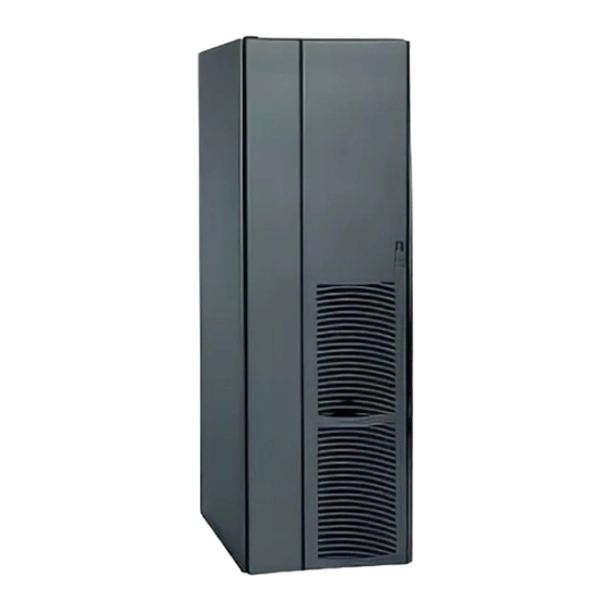
A DC-rated circuit breaker within each cabinet provides protection and servicing isolation. Figure 1‐1. Powerware 9390 Model IBC-S Battery Cabinet 9390 Integrated Battery Cabinet (Models IBC-S and IBC-L) Installation Manual S 164201536 Rev D EATON Powerware ® www.eaton.com/powerquality... -
Page 8: Battery Cabinet Configurations
1.2 UPS Systems Using Powerware 9390 Battery Cabinets Powerware 9390 40–80 kVA UPS (Model IBC-S and Model IBC-L) Powerware 9390 120–160 kVA UPS (Model IBC-L only) 9390 Integrated Battery Cabinet (Models IBC-S and IBC-L) Installation Manual S 164201536 Rev D EATON Powerware ®... -
Page 9: Using This Manual
The term standalonet refers to battery cabinets that are not physically attached to the UPS, are wired with external contractor-supplied wiring, and use a single overcurrent protection and disconnect device located near the batteries. 9390 Integrated Battery Cabinet (Models IBC-S and IBC-L) Installation Manual S 164201536 Rev D EATON Powerware ®... -
Page 10: Safety Warnings
A battery can cause electrical shock, burn from high short‐circuit current, or fire. Observe proper precautions. 9390 Integrated Battery Cabinet (Models IBC-S and IBC-L) Installation Manual S 164201536 Rev D EATON Powerware ® www.eaton.com/powerquality... -
Page 11: For More Information
Communication capabilities of the UPS system. Visit www.powerware.com or contact an Eaton Customer Service Representative for information on how to obtain copies of these manuals. 9390 Integrated Battery Cabinet (Models IBC-S and IBC-L) Installation Manual S 164201536 Rev D EATON Powerware ®... -
Page 12: Getting Help
Please call the Eaton Help Desk for Powerware products at: In the United States 1‐800‐843‐9433 or 1-919-870-3028 In Canada 1‐800‐461‐9166 All other countries Call your service representative 9390 Integrated Battery Cabinet (Models IBC-S and IBC-L) Installation Manual S 164201536 Rev D EATON Powerware ® www.eaton.com/powerquality... -
Page 13: Battery Cabinet Installation Plan And Unpacking
Clearance must be allowed in front of and above each cabinet for proper air circulation. See Drawing 164201536-2 on page A-4 for clearances. 9390 Integrated Battery Cabinet (Models IBC-S and IBC-L) Installation Manual S 164201536 Rev D EATON Powerware ®... -
Page 14: Environment Considerations
Battery control wiring requirements can be found on Drawing 164201536-8, starting on page A-17 and should be connected at the battery interface terminal block located inside the battery cabinet. 9390 Integrated Battery Cabinet (Models IBC-S and IBC-L) Installation Manual S 164201536 Rev D EATON Powerware ®... -
Page 15: Inspecting And Unpacking The Battery Cabinet
Figure 2‐1, and protected with outer protective packaging material. Figure 2‐1. Powerware 9390 Battery Cabinet as Shipped on Pallet (Model IBC-L shown) 9390 Integrated Battery Cabinet (Models IBC-S and IBC-L) Installation Manual S 164201536 Rev D EATON Powerware ®... - Page 16 1. Carefully inspect the outer packaging for evidence of damage during transit. C A U T I O N Do not install a damaged cabinet. Report any damage to the carrier and contact an Eaton Customer Service Representative immediately. 2. Use a forklift or pallet jack to move the packaged cabinet to the installation site, or as close as possible, before unpacking.
-
Page 17: Installing Battery Cabinets
Once the battery cabinets are installed and wired, return to the appropriate Powerware 9390 UPS Installation and Operation Manual, as referenced in paragraph 1.6, to complete the UPS wiring. 9390 Integrated Battery Cabinet (Models IBC-S and IBC-L) Installation Manual S 164201536 Rev D EATON Powerware ®... -
Page 18: Figure 3-1. Removing Shipping Supports
W A R N I N G SERIOUS INJURY MAY OCCUR. Battery cabinets are extremely heavy. If unloading instructions are not closely followed, cabinet may tip. 9390 Integrated Battery Cabinet (Models IBC-S and IBC-L) Installation Manual S 164201536 Rev D EATON Powerware ®... - Page 19 10. The battery cabinet is now ready to be rolled to its final location. 11. Repeat Steps 2 through 10 for each cabinet you are preparing to install. 9390 Integrated Battery Cabinet (Models IBC-S and IBC-L) Installation Manual S 164201536 Rev D EATON Powerware ®...
-
Page 20: Model Ibc-S Battery Cabinet Installation
UPS cabinet. Battery Cabinet UPS Cabinet Figure 3‐2. UPS with Line-up-and-Match IBC-S 9390 Integrated Battery Cabinet (Models IBC-S and IBC-L) Installation Manual S 164201536 Rev D EATON Powerware ® www.eaton.com/powerquality... -
Page 21: Figure 3-3. Ups To Ibc-S Joining Brackets
Refer to Appendix A of the appropriate Powerware 9390 UPS Installation and Operation Manual, as referenced in paragraph 1.6, for the location of the knockout plug. 9390 Integrated Battery Cabinet (Models IBC-S and IBC-L) Installation Manual S 164201536 Rev D EATON Powerware ®... -
Page 22: Figure 3-4. Ibc-S Bottom Joining Brackets And Ground Wire
Ò Ò Ò Ò Ò Ò Ò Ò Ò Ò Ò Ò Ò Ò Ò Ò Ò Ò Ò Ò Ò Ò Ò Ò Front of Battery Cabinet Front of UPS Cabinet Figure 3‐4. IBC-S Bottom Joining Brackets and Ground Wire 9390 Integrated Battery Cabinet (Models IBC-S and IBC-L) Installation Manual S 164201536 Rev D EATON Powerware ® www.eaton.com/powerquality... -
Page 23: Figure 3-5. Ibc-S Hanger Brackets
18. Proceed to paragraph 3.3.2. Hanger Bracket Location (Secured with Screws) Cabinet-to-Cabinet Cable Access Area (Each Side) Figure 3‐5. IBC-S Hanger Brackets 9390 Integrated Battery Cabinet (Models IBC-S and IBC-L) Installation Manual S 164201536 Rev D EATON Powerware ® www.eaton.com/powerquality... -
Page 24: Line-Up-And-Match Ibc-S Electrical Connections
UPS cabinet and connect to terminal strip TB2. Refer to the appropriate Powerware 9390 UPS Installation and Operation Manual, as referenced in paragraph 1.6, for UPS cabinet terminal locations. 9390 Integrated Battery Cabinet (Models IBC-S and IBC-L) Installation Manual S 164201536 Rev D EATON Powerware ®... -
Page 25: Figure 3-6. Ibc-S Battery String Connection
1.6, to complete the UPS wiring. Battery Breaker Fixed Right Battery Power Connector (Black) String Connectors (Red) Figure 3‐6. IBC-S Battery String Connection 9390 Integrated Battery Cabinet (Models IBC-S and IBC-L) Installation Manual S 164201536 Rev D EATON Powerware ® www.eaton.com/powerquality... -
Page 26: Figure 3-7. Ups With Standalone Ibc-S
Additional battery cabinets are supplied without cosmetic covers. Cosmetic covers must be ordered for the UPS cabinet and/or other ancillary cabinets. 9390 Integrated Battery Cabinet (Models IBC-S and IBC-L) Installation Manual S 164201536 Rev D 3-10 EATON Powerware ®... - Page 27 17. If not already secured, secure the side panel at the bottom using M4 hex-head screws previously removed. 18. Proceed to paragraph 3.3.4. 9390 Integrated Battery Cabinet (Models IBC-S and IBC-L) Installation Manual S 164201536 Rev D 3-11 EATON Powerware ®...
-
Page 28: Standalone Ibc-S Electrical Connections
Refer to the appropriate Powerware 9390 UPS Installation and Operation Manual, as referenced in paragraph 1.6, for top or bottom conduit landing locations. 9390 Integrated Battery Cabinet (Models IBC-S and IBC-L) Installation Manual S 164201536 Rev D 3-12 EATON Powerware ®... -
Page 29: Model Ibc-L Battery Cabinet Installation
To install an line-up-and-match battery system, proceed to paragraph 3.4.1. To install a standalone battery system, proceed to paragraph 3.4.3. 9390 Integrated Battery Cabinet (Models IBC-S and IBC-L) Installation Manual S 164201536 Rev D 3-13 EATON Powerware ®... -
Page 30: Figure 3-8. Ups With Line-Up-And-Match Ibc-L
The UPS cabinet, additional battery cabinets, and other ancillary cabinets are supplied without cosmetic covers. 9390 Integrated Battery Cabinet (Models IBC-S and IBC-L) Installation Manual S 164201536 Rev D 3-14 EATON Powerware ®... -
Page 31: Figure 3-9. Ups To Ibc-L Joining Brackets
9. Secure the battery cabinet position by lowering the leveling feet until cabinet is not resting on the casters. Ensure the cabinet is level and matches the height of the installed UPS cabinet. 9390 Integrated Battery Cabinet (Models IBC-S and IBC-L) Installation Manual S 164201536 Rev D 3-15 EATON Powerware ®... -
Page 32: Figure 3-10. Ibc-L Bottom Joining Brackets And Ground Wire
Ò Ò Ò Ò Ò Ò Ò Ò Ò Ò Ò Ò Ò Ò Ò Ò Ò Ò Ò Ò Ò Ò Ò Ò Ò Front of Battery Cabinet Front of UPS Cabinet Nuts from Kit Figure 3‐10. IBC-L Bottom Joining Brackets and Ground Wire 9390 Integrated Battery Cabinet (Models IBC-S and IBC-L) Installation Manual S 164201536 Rev D 3-16 EATON Powerware ® www.eaton.com/powerquality... -
Page 33: Figure 3-11. Ibc-L Battery Cabinet Hanger Brackets
19. Proceed to paragraph 3.4.2. Hanger Bracket Location (Secured with Screws) Cabinet-to-Cabinet Cable Access Area (Each Side) Figure 3‐11. IBC-L Battery Cabinet Hanger Brackets 9390 Integrated Battery Cabinet (Models IBC-S and IBC-L) Installation Manual S 164201536 Rev D 3-17 EATON Powerware ® www.eaton.com/powerquality... -
Page 34: Line-Up-And-Match Ibc-L Electrical Connections
UPS cabinet and connect to terminal strip TB2. Refer to the appropriate Powerware 9390 UPS Installation and Operation Manual, as referenced in paragraph 1.6, for UPS cabinet terminal locations. 9390 Integrated Battery Cabinet (Models IBC-S and IBC-L) Installation Manual S 164201536 Rev D 3-18 EATON Powerware ®... -
Page 35: Figure 3-12. Ibc-L Battery String Connection
1.6, to complete the UPS wiring. Battery Breaker Fixed Right Battery Power Connector (Black) String Connectors (Red) Figure 3‐12. IBC-L Battery String Connection 9390 Integrated Battery Cabinet (Models IBC-S and IBC-L) Installation Manual S 164201536 Rev D 3-19 EATON Powerware ® www.eaton.com/powerquality... -
Page 36: Figure 3-13. Ups With Standalone Ibc-L
(remote) installation, the first battery cabinet is supplied with two cosmetic covers. Additional battery cabinets are supplied without cosmetic covers. Cosmetic covers must be ordered for the UPS cabinet and/or other ancillary cabinets. 9390 Integrated Battery Cabinet (Models IBC-S and IBC-L) Installation Manual S 164201536 Rev D 3-20 EATON Powerware ®... - Page 37 18. If not already secured, secure the side panel at the bottom using M4 hex-head screws previously removed. 19. Proceed to paragraph 3.4.4. 9390 Integrated Battery Cabinet (Models IBC-S and IBC-L) Installation Manual S 164201536 Rev D 3-21 EATON Powerware ®...
-
Page 38: Standalone Battery Cabinet Electrical Connections
Refer to the appropriate Powerware 9390 UPS Installation and Operation Manual, as referenced in paragraph 1.6, for top or bottom conduit landing locations. 9390 Integrated Battery Cabinet (Models IBC-S and IBC-L) Installation Manual S 164201536 Rev D 3-22 EATON Powerware ®... - Page 39 16. After the battery cabinets are installed and wired, return to the appropriate Powerware 9390 UPS Installation and Operation Manual, as referenced in paragraph 1.6, to complete the UPS wiring. 9390 Integrated Battery Cabinet (Models IBC-S and IBC-L) Installation Manual S 164201536 Rev D 3-23 EATON Powerware ®...
-
Page 40: Completing The Installation Checklist
- Adequate lighting is provided around all battery cabinet equipment. - A remote battery disconnect control is mounted in its installed location and its wiring is terminated inside the battery cabinet (OPTIONAL). 9390 Integrated Battery Cabinet (Models IBC-S and IBC-L) Installation Manual S 164201536 Rev D 3-24 EATON Powerware ®... - Page 41 Installing Battery Cabinets Notes _________________________________________________________________________ _________________________________________________________________________ _________________________________________________________________________ _________________________________________________________________________ _________________________________________________________________________ _________________________________________________________________________ _________________________________________________________________________ _________________________________________________________________________ _________________________________________________________________________ _________________________________________________________________________ _________________________________________________________________________ _________________________________________________________________________ _________________________________________________________________________ _________________________________________________________________________ _________________________________________________________________________ _________________________________________________________________________ 9390 Integrated Battery Cabinet (Models IBC-S and IBC-L) Installation Manual S 164201536 Rev D 3-25 EATON Powerware ® www.eaton.com/powerquality...
- Page 42 Installing Battery Cabinets This page intentionally left blank. 9390 Integrated Battery Cabinet (Models IBC-S and IBC-L) Installation Manual S 164201536 Rev D 3-26 EATON Powerware ® www.eaton.com/powerquality...
- Page 43 Conduit and Wire Entry Locations Standalone Battery Cabinets 164201536-7 Battery Power and Interface Terminal Locations 164201536-8 Interface Wiring Installation Notes and Terminal Connections 164201536-9 Battery Cabinet Dimensions 9390 Integrated Battery Cabinet (Models IBC-S and IBC-L) Installation Manual S 164201536 Rev D EATON Powerware ® www.eaton.com/powerquality...
- Page 44 Installation Information MODEL IBC-S DESCRIPTION: POWERWARE 9390 INTEGRATED BATTERY CABINETS (IBC) DRAWING NO: SHEET: 164201536-1 1 of 2 REVISION: B DATE: 091504 9390 Integrated Battery Cabinet (Models IBC-S and IBC-L) Installation Manual S 164201536 Rev D EATON Powerware ® www.eaton.com/powerquality...
- Page 45 Installation Information MODEL IBC-L DESCRIPTION: POWERWARE 9390 INTEGRATED BATTERY CABINETS (IBC) DRAWING NO: SHEET: 164201536-1 2 of 2 REVISION: B DATE: 091504 9390 Integrated Battery Cabinet (Models IBC-S and IBC-L) Installation Manual S 164201536 Rev D EATON Powerware ® www.eaton.com/powerquality...
- Page 46 25°C (77°F). DESCRIPTION: PHYSICAL FEATURES AND REQUIREMENTS DRAWING NO: SHEET: 164201536-2 1 of 1 REVISION: DATE: 070804 9390 Integrated Battery Cabinet (Models IBC-S and IBC-L) Installation Manual S 164201536 Rev D EATON Powerware ® www.eaton.com/powerquality...
- Page 47 Installation Information TWO POLE BREAKER WIRING DESCRIPTION: BATTERY CABINET SCHEMATICS DRAWING NO: SHEET: 164201536-3 1 of 3 REVISION: DATE: 061504 9390 Integrated Battery Cabinet (Models IBC-S and IBC-L) Installation Manual S 164201536 Rev D EATON Powerware ® www.eaton.com/powerquality...
- Page 48 Installation Information THREE POLE BREAKER WIRING DESCRIPTION: BATTERY CABINET SCHEMATICS DRAWING NO: SHEET: 164201536-3 2 of 3 REVISION: DATE: 061504 9390 Integrated Battery Cabinet (Models IBC-S and IBC-L) Installation Manual S 164201536 Rev D EATON Powerware ® www.eaton.com/powerquality...
- Page 49 FIRST AND MIDDLE CABINETS IN MULTI-CABINET INSTALLATIONS DESCRIPTION: BATTERY CABINET SCHEMATICS BATTERY BREAKER CB1 CONTROL DRAWING NO: SHEET: 164201536-3 3 of 3 REVISION: B DATE: 091504 9390 Integrated Battery Cabinet (Models IBC-S and IBC-L) Installation Manual S 164201536 Rev D EATON Powerware ® www.eaton.com/powerquality...
- Page 50 Customer wiring (1): See Table D DRAWING NO: SHEET: 164201536-4 1 of 1 to size customer supplied wiring. REVISION: B DATE: 093004 9390 Integrated Battery Cabinet (Models IBC-S and IBC-L) Installation Manual S 164201536 Rev D EATON Powerware ® www.eaton.com/powerquality...
- Page 51 Nm (lb in) Battery 7/16I slot 5.6 (50) DESCRIPTION: BATTERY WIRING INSTALLATION NOTES DRAWING NO: SHEET: 164201536-5 1 of 3 REVISION: B DATE: 093004 9390 Integrated Battery Cabinet (Models IBC-S and IBC-L) Installation Manual S 164201536 Rev D EATON Powerware ® www.eaton.com/powerquality...
- Page 52 DESCRIPTION: BATTERY WIRING INSTALLATION NOTES DRAWING NO: SHEET: 164201536-5 2 of 3 REVISION: C DATE: 032406 9390 Integrated Battery Cabinet (Models IBC-S and IBC-L) Installation Manual S 164201536 Rev D A-10 EATON Powerware ® www.eaton.com/powerquality...
- Page 53 DESCRIPTION: BATTERY WIRING INSTALLATION NOTES DRAWING NO: SHEET: 164201536-5 3 of 3 REVISION: C DATE: 032406 9390 Integrated Battery Cabinet (Models IBC-S and IBC-L) Installation Manual S 164201536 Rev D A-11 EATON Powerware ® www.eaton.com/powerquality...
- Page 54 MODEL IBC-S DESCRIPTION: CONDUIT AND WIRE ENTRY LOCATIONS STAND‐ALONE BATTERY CABINETS DRAWING NO: SHEET: 164201536-6 1 of 2 REVISION: B DATE: 091504 9390 Integrated Battery Cabinet (Models IBC-S and IBC-L) Installation Manual S 164201536 Rev D A-12 EATON Powerware ® www.eaton.com/powerquality...
- Page 55 MODEL IBC-L DESCRIPTION: CONDUIT AND WIRE ENTRY LOCATIONS STAND‐ALONE BATTERY CABINETS DRAWING NO: SHEET: 164201536-6 2 of 2 REVISION: B DATE: 091504 9390 Integrated Battery Cabinet (Models IBC-S and IBC-L) Installation Manual S 164201536 Rev D A-13 EATON Powerware ® www.eaton.com/powerquality...
- Page 56 GROUNDING STUD MODEL IBC-S DESCRIPTION: BATTERY POWER AND INTERFACE TERMINAL LOCATIONS DRAWING NO: SHEET: 164201536-7 1 of 3 REVISION: B DATE: 091504 9390 Integrated Battery Cabinet (Models IBC-S and IBC-L) Installation Manual S 164201536 Rev D A-14 EATON Powerware ® www.eaton.com/powerquality...
- Page 57 TERMINAL LOCATIONS the UPS and battery cabinet and between DRAWING NO: SHEET: battery cabinets. 164201536-7 2 of 3 REVISION: B DATE: 091504 9390 Integrated Battery Cabinet (Models IBC-S and IBC-L) Installation Manual S 164201536 Rev D A-15 EATON Powerware ® www.eaton.com/powerquality...
- Page 58 TERMINAL LOCATIONS the UPS and battery cabinet and between DRAWING NO: SHEET: battery cabinets. 164201536-7 3 of 3 REVISION: B DATE: 091504 9390 Integrated Battery Cabinet (Models IBC-S and IBC-L) Installation Manual S 164201536 Rev D A-16 EATON Powerware ® www.eaton.com/powerquality...
- Page 59 MULTIPLE BATTERY CABINETS DESCRIPTION: INTERFACE WIRING INSTALLATION NOTES AND TERMINAL CONNECTIONS DRAWING NO: SHEET: 164201536-8 1 of 2 REVISION: C DATE: 032406 9390 Integrated Battery Cabinet (Models IBC-S and IBC-L) Installation Manual S 164201536 Rev D A-17 EATON Powerware ® www.eaton.com/powerquality...
- Page 60 CABINET CABINET DESCRIPTION: INTERFACE WIRING INSTALLATION NOTES AND TERMINAL CONNECTIONS DRAWING NO: SHEET: 164201536-8 2 of 2 REVISION: B DATE: 091504 9390 Integrated Battery Cabinet (Models IBC-S and IBC-L) Installation Manual S 164201536 Rev D A-18 EATON Powerware ® www.eaton.com/powerquality...
- Page 61 MODEL IBC-S DESCRIPTION: BATTERY CABINET DIMENSIONS DRAWING NO: SHEET: 164201536-9 1 of 5 REVISION: B DATE: 091504 Dimensions are in millimeters [inches] 9390 Integrated Battery Cabinet (Models IBC-S and IBC-L) Installation Manual S 164201536 Rev D A-19 EATON Powerware ® www.eaton.com/powerquality...
- Page 62 MODEL IBC-S DESCRIPTION: BATTERY CABINET DIMENSIONS DRAWING NO: SHEET: 164201536-9 2 of 5 REVISION: B DATE: 091504 Dimensions are in millimeters [inches] 9390 Integrated Battery Cabinet (Models IBC-S and IBC-L) Installation Manual S 164201536 Rev D A-20 EATON Powerware ® www.eaton.com/powerquality...
- Page 63 MODEL IBC-L DESCRIPTION: BATTERY CABINET DIMENSIONS DRAWING NO: SHEET: 164201536-9 3 of 5 REVISION: B DATE: 091504 Dimensions are in millimeters [inches] 9390 Integrated Battery Cabinet (Models IBC-S and IBC-L) Installation Manual S 164201536 Rev D A-21 EATON Powerware ® www.eaton.com/powerquality...
- Page 64 MODEL IBC-L DESCRIPTION: BATTERY CABINET DIMENSIONS DRAWING NO: SHEET: 164201536-9 4 of 5 REVISION: B DATE: 091504 Dimensions are in millimeters [inches] 9390 Integrated Battery Cabinet (Models IBC-S and IBC-L) Installation Manual S 164201536 Rev D A-22 EATON Powerware ® www.eaton.com/powerquality...
- Page 65 MODEL IBC-L DESCRIPTION: BATTERY CABINET DIMENSIONS DRAWING NO: SHEET: 164201536-9 5 of 5 REVISION: B DATE: 091504 Dimensions are in millimeters [inches] 9390 Integrated Battery Cabinet (Models IBC-S and IBC-L) Installation Manual S 164201536 Rev D A-23 EATON Powerware ® www.eaton.com/powerquality...
- Page 66 Installation Information This page intentionally left blank. 9390 Integrated Battery Cabinet (Models IBC-S and IBC-L) Installation Manual S 164201536 Rev D A-24 EATON Powerware ® www.eaton.com/powerquality...
- Page 67 OTHER LIMITATIONS: Eaton's obligations under this Warranty are expressly conditioned upon receipt by Eaton of all payments due to it (including interest charges, if any). During such time as Eaton has not received payment of any amount due to it for the Product, in accordance with the contract terms under which the Product is sold, Eaton shall have no obligation under this Warranty.
- Page 68 Warranty This page intentionally left blank. 9390 Integrated Battery Cabinet (Models IBC-S and IBC-L) Installation Manual S 164201536 Rev D EATON Powerware ® www.eaton.com/powerquality...
- Page 70 *164201536D* 164201536 D...
Need help?
Do you have a question about the IBC-S and is the answer not in the manual?
Questions and answers