Eaton Powerware 9390 Installation And Operation Manual
Integrated distribution cabinet
Hide thumbs
Also See for Powerware 9390:
- Installation and operation manual (232 pages) ,
- Brochure & specs (20 pages) ,
- Specifications manual (16 pages)
Table of Contents
Advertisement
Quick Links
Advertisement
Table of Contents

Related Manuals for Eaton Powerware 9390


Summary of Contents for Eaton Powerware 9390
- Page 2 CE MANUEL CONTIENT DES CONSIGNES DE SÉCURITÉ IMPORTANTES Powerware is a registered trademark of Eaton Electrical Inc. ECopyright 2005–2007 Eaton Corporation, Raleigh, NC, USA. All rights reserved. No part of this document may be reproduced in any way without the express written approval of Eaton Corporation.
-
Page 3: Table Of Contents
......... . Unloading the Powerware 9390 IDC-160 from the Pallet . - Page 4 ..............EATON Powerware 9390 IDC Installation and Operation Manual S 164201560 Rev C www.powerware.com...
- Page 5 ......Figure 3-1. Removing Front Shipping Bracket on the Powerware 9390 160 kVA IDC .
- Page 6 This page intentionally left blank. EATON Powerware 9390 IDC Installation and Operation Manual S 164201560 Rev C www.powerware.com ®...
-
Page 7: Introduction
The Powerware 9390 Integrated Distribution Cabinet (IDC) is designed for use with the ® Powerware 9390 family of three-phase uninterruptible power systems (UPSs). The IDC provides the following custom configurable features, enabling adaptation and expansion without costly electrical rework: Power distribution options distribute power to servers or racks via distribution panelboards, or distribute power to larger loads via distribution circuit breakers. -
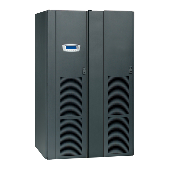
Page 8: Figure 1-1. Powerware 9390 160 Kva Idc Cabinet
- one to six 100-250A adjustable distribution breakers - one 225A distribution panel and one to three 100-250A adjustable distribution breakers Figure 1-1. Powerware 9390 160 kVA IDC Cabinet EATON Powerware 9390 IDC Installation and Operation Manual S 164201560 Rev C www.powerware.com... -
Page 9: Installation Information
Introduction 1.2 Using This Manual This manual describes how to install and operate the Powerware 9390 IDC. Read and understand the procedures described in this manual to ensure trouble-free installation and operation. The information in this manual is divided into the sections and chapters listed. At a minimum, Chapters 1 through 3 and Chapter 5 should be examined. -
Page 10: Conventions Used In This Manual
The term standalone refers to cabinets that are not physically attached to the UPS, and are wired with external contractor-supplied wiring. EATON Powerware 9390 IDC Installation and Operation Manual S 164201560 Rev C www.powerware.com... -
Page 11: Safety Warnings
Keep surroundings uncluttered, clean, and free from excess moisture. Observe all DANGER, CAUTION, and WARNING notices affixed to the inside and outside of the equipment. EATON Powerware 9390 IDC Installation and Operation Manual S 164201560 Rev C www.powerware.com ®... -
Page 12: For More Information
Introduction 1.5 For More Information Refer to the Powerware 9390 UPS (100–160 kVA) Installation and Operation Manual for the following additional information: UPS cabinet, optional components, and accessory installation instructions, including site preparation, planning for installation, and wiring and safety information. Detailed illustrations of cabinets and optional accessories with dimensional and connection point drawings are provided. -
Page 13: Section I - Installation
Section I Installation EATON Powerware 9390 IDC Installation and Operation Manual S 164201560 Rev C www.powerware.com ®... - Page 14 This page intentionally left blank. EATON Powerware 9390 IDC Installation and Operation Manual S 164201560 Rev C www.powerware.com ®...
-
Page 15: Idc Installation Plan And Unpacking
For the IDC to operate at peak efficiency, the installation site should meet the environmental parameters outlined in this manual. If the IDC is to be operated at an altitude higher than 1500m (5000 ft), contact your Eaton service representative for important information about high altitude operation. The operating environment must... -
Page 16: Environmental Considerations
1. Carefully inspect the outer packaging for evidence of damage during transit. C A U T I O N Do not install a damaged cabinet. Report any damage to the carrier and contact your Eaton service representative immediately. 2. Use a forklift or pallet jack to move the packaged cabinet to the installation site, or as close as possible, before unpacking. - Page 17 6. Inspect the contents for any evidence of physical damage, and compare each item with the Bill of Lading. If damage has occurred or shortages are evident, contact your Eaton service representative immediately to determine the extent of the damage and its impact upon further installation.
- Page 18 IDC Installation Plan and Unpacking This page intentionally left blank. EATON Powerware 9390 IDC Installation and Operation Manual S 164201560 Rev C www.powerware.com ®...
-
Page 19: Installing The Idc
Details about control wiring are provided in each procedure. Drawing 164201560-8 and Table J and NO TAG, starting on page A-23, identify the control wiring terminations. Refer to the Powerware 9390 UPS (100–160 kVA) Installation and Operation Manual for UPS cabinet installation, wiring information, and conduit and terminal locations. - Page 20 9. Discard or recycle the pallet and unused shipping brackets in a responsible manner. 10. Roll the cabinet to its final installation location. 11. Proceed to paragraph 3.3. EATON Powerware 9390 IDC Installation and Operation Manual S 164201560 Rev C www.powerware.com ®...
- Page 21 BOLT REMOVABLE SKID PALLET SHIPPING BRACKET SHIPPING BOLTS BRACKET FRONT SHIPPING BOLTS BRACKET FRONT VIEW Figure 3-1. Removing Front Shipping Bracket on the Powerware 9390 IDC EATON Powerware 9390 IDC Installation and Operation Manual S 164201560 Rev C www.powerware.com ®...
- Page 22 SHIPPING BRACKET SHIPPING BRACKET BOLTS REMOVABLE SKID REAR SKID BOLT SHIPPING BRACKET BOLTS REAR VIEW Figure 3-2. Removing Rear Shipping Bracket on the Powerware 9390 IDC EATON Powerware 9390 IDC Installation and Operation Manual S 164201560 Rev C www.powerware.com ®...
-
Page 23: Idc Cabinet Installation
To install a standalone IDC, proceed to paragraph 3.3.2. 3.3.1 Line-up-and-Match IDC Installation Use this procedure to install the IDC adjacent to the Powerware 9390 UPS cabinet (see Figure 3-3). The recommended location is to the right of the UPS cabinet. This procedure assumes the IDC is located to the right of the UPS cabinet. - Page 24 IDC. Save the cover, screws, and brackets for later use. 10. Remove the knockouts, as required, on the bottom right side of the UPS cabinet inside panel. Refer to the Powerware 9390 UPS (100–160 kVA) Installation and Operation Manual for the location of the knockout plug.
-
Page 25: Figure 3-4. Idc Knockout Plug And Hanger Bracket Locations
KNOCKOUTS. REMOVE KNOCKOUTS, AS REQUIRED, TO ROUTE WIRES BETWEEN CABINETS. (INSTALL NYLON GROMMET AFTER REMOVAL OF KNOCKOUTS.) Figure 3-4. IDC Knockout Plug and Hanger Bracket Locations EATON Powerware 9390 IDC Installation and Operation Manual S 164201560 Rev C www.powerware.com ®... - Page 26 IDC cabinet (see Figure 3-5). 25. Secure the bracket to the hinges with hardware from the field kit. 26. Proceed to paragraph 3.3.1.1. EATON Powerware 9390 IDC Installation and Operation Manual S 164201560 Rev C www.powerware.com ®...
-
Page 27: Figure 3-5. Ups To Idc Joining Brackets
Top View with Small Bracket UPS Cabinet Bracket from Kit Existing Hinge Existing Hinge Nuts from Kit Front View with Large Bracket Figure 3-5. UPS to IDC Joining Brackets EATON Powerware 9390 IDC Installation and Operation Manual S 164201560 Rev C www.powerware.com ®... -
Page 28: Installing Idc Line-Up-And-Match Power Wiring
Remove the IDC cabinet top or bottom conduit landing plate to drill or punch NOTE conduit holes, or remove knockouts (see Drawing 164201560-6 on page A-15). Refer to the Powerware 9390 UPS (100–160 kVA) Installation and Operation NOTE Manual for UPS cabinet wiring information, and conduit and terminal locations. - Page 29 11. IDC-to-UPS rectifier and bypass wiring harnesses are supplied inside the IDC. Route the harnesses through the knockouts in the side of the cabinets to the UPS rectifier and bypass terminals. Refer to the Powerware 9390 UPS (100–160 kVA) Installation and Operation Manual for UPS cabinet terminal locations and termination requirements.
-
Page 30: Installing Line-Up-And-Match P1 And P2 Interface Connections
6. Route and connect the Maintenance Bypass switch wiring from the IDC to the UPS cabinet. See Appendix A and refer to the Powerware 9390 UPS (100–160 kVA) Installation and Operation Manual for UPS cabinet terminal locations. -
Page 31: Standalone Idc Installation
Use this procedure to install a separately located IDC (see Figure 3-6). Figure 3-6. UPS with Standalone IDC 1. Verify that the UPS is properly installed and secured. Refer to the Powerware 9390 UPS (100–160 kVA) Installation and Operation Manual for installation instructions. -
Page 32: Installing Idc Standalone Power Wiring
(see Drawing 164201560-6 on page A-15). NOTE Refer to the Powerware 9390 UPS (100–160 kVA) Installation and Operation Manual for UPS cabinet wiring information, and conduit and terminal locations. 1. Verify the UPS system is turned off and all power sources are removed. Refer to the Powerware 9390 UPS (100–160 kVA) Installation and Operation Manual for... - Page 33 Step 13. 11. Route the UPS rectifier and bypass input cables from the UPS to the IDC terminal blocks. Refer to the Powerware 9390 UPS (100–160 kVA) Installation and Operation Manual for UPS cabinet terminal locations and termination requirements. See Drawing 164201560-7, starting on page A-17, for IDC wiring access information and terminal locations.
-
Page 34: Installing Standalone P1 And P2 Interface Connections
6. Route and connect the Maintenance Bypass switch wiring from the IDC to the UPS cabinet. See Appendix A and refer to the Powerware 9390 UPS (100–160 kVA) Installation and Operation Manual for UPS cabinet terminal locations. -
Page 35: Initial Startup
14. Close the door and secure the latch. 3.4 Initial Startup Startup and operational checks must be performed by an authorized Eaton Customer Service Engineer, or the warranty terms as specified on page W-1 become void. This service is offered as part of the sales contract for the UPS system. Contact service in advance (usually a two week notice is required) to reserve a preferred startup date. - Page 36 - Transformer overtemperature shutdown sensor is connected to the REPO. (OPTIONAL) - The debris shield covering the IDC cabinet ventilation grill is removed. - Startup and operational checks are performed by an authorized Eaton Customer Service Engineer. 3-18 EATON Powerware 9390 IDC Installation and Operation Manual S 164201560 Rev C www.powerware.com...
- Page 37 Installing the IDC Notes _________________________________________________________________________ _________________________________________________________________________ _________________________________________________________________________ _________________________________________________________________________ _________________________________________________________________________ _________________________________________________________________________ _________________________________________________________________________ _________________________________________________________________________ _________________________________________________________________________ _________________________________________________________________________ _________________________________________________________________________ _________________________________________________________________________ _________________________________________________________________________ _________________________________________________________________________ _________________________________________________________________________ _________________________________________________________________________ 3-19 EATON Powerware 9390 IDC Installation and Operation Manual S 164201560 Rev C www.powerware.com ®...
- Page 38 Installing the IDC This page intentionally left blank. 3-20 EATON Powerware 9390 IDC Installation and Operation Manual S 164201560 Rev C www.powerware.com ®...
-
Page 39: Section Ii - Operation
Section II Operation 3-21 EATON Powerware 9390 IDC Installation and Operation Manual S 164201560 Rev C www.powerware.com ®... - Page 40 This page intentionally left blank. 3-22 EATON Powerware 9390 IDC Installation and Operation Manual S 164201560 Rev C www.powerware.com ®...
-
Page 41: Understanding Idc Operation
The critical load is not protected while the UPS is in Maintenance Bypass mode. Figure 4-2 shows the path of electrical power through the IDC when operating in Maintenance Bypass mode. EATON Powerware 9390 IDC Installation and Operation Manual S 164201560 Rev C www.powerware.com ®... -
Page 42: Figure 4-1. Path Of Current Through The Idc In Ups Mode
INTEGRATED DISTRIBUTION CABINET MAIN POWER FLOW IN UPS MODE MAIN POWER FLOW IN MAINTENANCE BYPASS MODE Figure 4-1. Path of Current Through the IDC in UPS Mode EATON Powerware 9390 IDC Installation and Operation Manual S 164201560 Rev C www.powerware.com ®... -
Page 43: Figure 4-2. Path Of Current Through The Idc In Maintenance Bypass Mode
INTEGRATED DISTRIBUTION CABINET MAIN POWER FLOW IN UPS MODE MAIN POWER FLOW IN MAINTENANCE BYPASS MODE Figure 4-2. Path of Current Through the IDC in Maintenance Bypass Mode EATON Powerware 9390 IDC Installation and Operation Manual S 164201560 Rev C www.powerware.com ®... - Page 44 Understanding IDC Operation This page intentionally left blank. EATON Powerware 9390 IDC Installation and Operation Manual S 164201560 Rev C www.powerware.com ®...
-
Page 45: Idc Features, Options, Controls, And Operation
Line-up-and-match cabinets are wired through the side panels of the units. EATON Powerware 9390 IDC Installation and Operation Manual S 164201560 Rev C www.powerware.com ®... -
Page 46: Expansion
Maintenance Bypass switch in situations where you must instantaneously control the output to the critical load. An external 120 Vac source is required to operate the shunt trip. EATON Powerware 9390 IDC Installation and Operation Manual S 164201560 Rev C www.powerware.com ®... -
Page 47: Symbols
5.4 IDC Controls Figure 5-1 through Figure 5-3 identify and show the location of the controls on the Powerware 9390 160 kVA IDC. The descriptions provide a brief overview of the IDC controls, and standard and optional features. NOTE Read the operation sections of this manual and the Powerware 9390 UPS (100–160 kVA) Installation and Operation Manual, and have thorough knowledge of... - Page 48 TYPE CH BREAKERS) DISTRIBUTION PANEL PB1 (USE CUTLER-HAMMER TYPE CH BREAKERS) DISTRIBUTION PANEL PB2 INPUT BREAKER CB20 Figure 5-1. Powerware 9390 IDC Controls – with Distribution Panel Option EATON Powerware 9390 IDC Installation and Operation Manual S 164201560 Rev C www.powerware.com ®...
- Page 49 OPTIONAL DISTRIBUTION DISTRIBUTION BREAKER CB22 BREAKER CB12 OPTIONAL OPTIONAL DISTRIBUTION DISTRIBUTION BREAKER CB23 BREAKER CB13 Figure 5-2. Powerware 9390 IDC Controls – with Distribution Breaker Option EATON Powerware 9390 IDC Installation and Operation Manual S 164201560 Rev C www.powerware.com ®...
- Page 50 RECTIFIER INPUT BYPASS INPUT BREAKER (RIB) BREAKER (BIB) MAINTENANCE BYPASS SWITCH MAINTENANCE (MBP) ISOLATION SWITCH (MIS) Figure 5-3. Powerware 9390 IDC Controls – with No Distribution EATON Powerware 9390 IDC Installation and Operation Manual S 164201560 Rev C www.powerware.com ®...
-
Page 51: Idc Operation
Distribution Panel Branch Breakers (if installed) OPEN 3. Start the UPS in Normal mode according to the instructions in the Operation chapter of the Powerware 9390 UPS (100–160 kVA) Installation and Operation Manual. 4. Close the IDC Distribution Panel Input Breakers (if installed) or the Distribution Breakers (if installed). - Page 52 8. Slide the interlock plate up until the standoff aligns with the Bypass arrow (see Figure 5-4). 9. Retighten the interlock knob. 10. Open the MIS. 11. Open the BIB and RIB if installed. EATON Powerware 9390 IDC Installation and Operation Manual S 164201560 Rev C www.powerware.com ®...
-
Page 53: Transferring The Ups From Maintenance Bypass
5. Slide the interlock plate up until the standoff aligns with the Bypass arrow (see Figure 5-4). 6. Retighten the interlock knob. 7. Open the MBP. 8. Transfer the UPS to Normal mode. EATON Powerware 9390 IDC Installation and Operation Manual S 164201560 Rev C www.powerware.com ®... -
Page 54: Using The Remote Emergency Power-Off Switch
Do not attempt to restart the system after REPO until the cause of the shutdown has been identified and cleared. 2. To restart the UPS after using the REPO pushbutton, reset the REPO switch and then follow the procedures in the Operation chapter of the Powerware 9390 UPS (100–160 kVA) Installation and Operation Manual. 5-10 EATON Powerware 9390 IDC Installation and Operation Manual S 164201560 Rev C www.powerware.com... - Page 55 IDC Features, Options, Controls, and Operation INTERLOCK STANDOFF KNOB MAINTENANCE BYPASS POSITION Figure 5-4. Powerware 9390 IDC Controls - Interlock Operation 5-11 EATON Powerware 9390 IDC Installation and Operation Manual S 164201560 Rev C www.powerware.com ®...
- Page 56 IDC Features, Options, Controls, and Operation This page intentionally left blank. 5-12 EATON Powerware 9390 IDC Installation and Operation Manual S 164201560 Rev C www.powerware.com ®...
-
Page 57: Maintaining The Idc
3. Verify the operating environment is within the parameters specified in Chapter 7, “Product Specifications”and Drawing 164201560-2 on page A-4. 4. Record the check results and any corrective actions in a suitable log. EATON Powerware 9390 IDC Installation and Operation Manual S 164201560 Rev C www.powerware.com ®... -
Page 58: Periodic Maintenance
6.4 Maintenance Training A basic training course, available from Eaton, gives you a competent working knowledge of the UPS system operation and teaches you how to perform first level corrective maintenance. For more information about training and other services, contact the Eaton Help Desk for Powerware products (see page 1-6). -
Page 59: Product Specifications
Chapter 7 Product Specifications 7.1 Model Number The IDC is housed in a free-standing cabinet with safety shields behind the doors. System Model Frequency Powerware 9390 160 kVA 60 Hz Powerware 9390 120 kVA 60 Hz 7.2 IDC Input Operating Input Voltage 480 Vac nominal (60 Hz) (Nominal +10/–15%) - Page 60 Product Specifications This page intentionally left blank. EATON Powerware 9390 IDC Installation and Operation Manual S 164201560 Rev C www.powerware.com ®...
-
Page 61: Installation Information
The information in this appendix will help during the planning and installation of the Integrated Distribution Cabinet (IDC). This appendix contains the following drawings: 164201560-1 Typical Powerware 9390 UPS System with Integrated Distribution Cabinet 164201560-2 Physical Features and Requirements 164201560-3... - Page 62 Installation Information BATTERY CABINET UPS CABINET IDC WITHOUT TOP ENTRY OPTION DESCRIPTION: TYPICAL POWERWARE 9390 UPS SYSTEM WITH INTEGRATED DISTRIBUTION CABINET DRAWING NO: SHEET: 164201560---1 1 of 2 REVISION: DATE: 071504 EATON Powerware 9390 IDC Installation and Operation Manual S 164201560 Rev C www.powerware.com...
- Page 63 Installation Information BATTERY CABINET UPS CABINET IDC WITH TOP ENTRY OPTION DESCRIPTION: TYPICAL POWERWARE 9390 UPS SYSTEM WITH INTEGRATED DISTRIBUTION CABINET DRAWING NO: SHEET: 164201560---1 2 of 2 REVISION: DATE: 071504 EATON Powerware 9390 IDC Installation and Operation Manual S 164201560 Rev C www.powerware.com...
- Page 64 Weight kg (lb) Component/Model Shipping Installed Point Loading Powerware 9390 IDC Cabinet with Transformer 1021 (2250) 991 (2185) 4 at 247.8 (546.3) and Maintenance Bypass Breakers NOTES: 1. For IDC with Distribution Panels, add 11.3 kg (25 lb) for each panel.
- Page 65 160 kVA with Transformer 480/208 14.8 (3.6) 120 kVA with Transformer 480/208 11.1 (2.7) DESCRIPTION: PHYSICAL FEATURES AND REQUIREMENTS DRAWING NO: SHEET: 164201560---2 2 of 2 REVISION: DATE: 113004 EATON Powerware 9390 IDC Installation and Operation Manual S 164201560 Rev C www.powerware.com ®...
- Page 66 100--- 250A 100--- 250A ADJUSTABLE ADJUSTABLE DISTRIBUTION DISTRIBUTION BREAKERS BREAKERS OUTPUT TO OUTPUT TO CRITICAL CRITICAL POWERWARE 9390 LOAD LOAD UPS CABINET 480/480V OUTPUT TO OUTPUT CRITICAL TERMINAL LOAD BLOCK AVAILABLE WITH OPTIONS FOR ONE OR TWO 42 POLE 225A...
- Page 67 Installation Information AC INPUT TO BYPASS FACTORY SUPPLIED FOR INTEGRAL CABINET INSTALLATIONS OPTIONS E51, E52, POWERWARE 9390 IDC E57, E58, BYPASS INPUT BREAKER CB3 (BIB) MAINTENANCE E6, E7, E1, E2, E3 BYPASS SWITCH SINGLE FEED E8, E12 JUMPER CB1 (MBP)
- Page 68 100--- 250A 100--- 250A ADJUSTABLE ADJUSTABLE DISTRIBUTION DISTRIBUTION BREAKERS BREAKERS OUTPUT TO OUTPUT TO CRITICAL CRITICAL POWERWARE 9390 LOAD LOAD UPS CABINET 480/480V OUTPUT TO OUTPUT CRITICAL TERMINAL LOAD BLOCK AVAILABLE WITH OPTIONS FOR ONE OR TWO 42 POLE 225A...
- Page 69 NOTE: Branch circuit breakers for PB1 and PB2 provided by customer. DESCRIPTION: IDC DISTRIBUTION PANEL SCHEMATIC DRAWING NO: SHEET: 164201560---4 1 of 1 REVISION: DATE: 113004 EATON Powerware 9390 IDC Installation and Operation Manual S 164201560 Rev C www.powerware.com ®...
- Page 70 (3) Phases, (1) Neutral--- if required, (1) Ground AC Output from Output Terminal Block to Wire output in accordance with national and local electrical codes. Refer to the Powerware 9390 UPS (100–160 kVA) Installation and Operation Critical Load Manual for output current rating and wire size.
- Page 71 Refer to Section I of this manual for installation instructions. Refer to the Powerware 9390 UPS (100–160 kVA) Installation and Operation Manual for UPS cabinet conduit and terminal locations. Terminals are UL and CSA rated at 90˚C. Refer to Table E for power cable terminations.
- Page 72 42 – #4---#14 2.8 (25) Slotted E28, E29 #10---#14: 2.3 (20) DESCRIPTION: POWER WIRING INSTALLATION NOTES DRAWING NO: SHEET: 164201560---5 3 of 4 REVISION: DATE: 123004 A-12 EATON Powerware 9390 IDC Installation and Operation Manual S 164201560 Rev C www.powerware.com ®...
- Page 73 Table F in accordance with the NEC, ANSI/NFPA 70. DESCRIPTION: POWER WIRING INSTALLATION NOTES DRAWING NO: SHEET: 164201560---5 4 of 4 REVISION: DATE: 113004 A-13 EATON Powerware 9390 IDC Installation and Operation Manual S 164201560 Rev C www.powerware.com ®...
- Page 74 Table H. Use the dial on each breaker to adjust as necessary. Table H. MBP , BIB, and RIB Settings 160 kVA Breaker UPS Model Continuous Current (Ir) Setting Powerware 9390---100 150A Powerware 9390---120 175A Powerware 9390---160 250A Verify the settings of the installed MIS matches the values listed in Table I. Use the dial on the breaker to adjust as necessary.
- Page 75 PANEL TO TO DRILL OR PUNCH CONDUIT HOLES, OR REMOVE DESCRIPTION: KNOCKOUTS.) CONDUIT AND WIRE ENTRY LOCATIONS DRAWING NO: SHEET: 164201560---6 1 of 2 REVISION: DATE: 123004 A-15 EATON Powerware 9390 IDC Installation and Operation Manual S 164201560 Rev C www.powerware.com ®...
- Page 76 ROUTE WIRES BETWEEN CABINETS. (INSTALL NYLON GROMMET AFTER REMOVAL OF KNOCKOUTS.) DESCRIPTION: CONDUIT AND WIRE ENTRY LOCATIONS DRAWING NO: SHEET: 164201560---6 2 of 2 REVISION: DATE: 123004 A-16 EATON Powerware 9390 IDC Installation and Operation Manual S 164201560 Rev C www.powerware.com ®...
- Page 77 NOTE: Metal shields covering wiring terminals DRAWING NO: SHEET: 164201560---7 1 of 6 must be removed or opened to gain access to terminals. REVISION: DATE: 123004 A-17 EATON Powerware 9390 IDC Installation and Operation Manual S 164201560 Rev C www.powerware.com ®...
- Page 78 NOTE: Metal shields covering wiring terminals must be removed or opened to gain DRAWING NO: SHEET: 164201560---7 2 of 6 access to terminals. REVISION: DATE: 123004 A-18 EATON Powerware 9390 IDC Installation and Operation Manual S 164201560 Rev C www.powerware.com ®...
- Page 79 NOTE: Metal shields covering wiring terminals must be removed or opened to gain DRAWING NO: SHEET: 164201560---7 3 of 6 access to terminals. REVISION: DATE: 123004 A-19 EATON Powerware 9390 IDC Installation and Operation Manual S 164201560 Rev C www.powerware.com ®...
- Page 80 AC INPUT TO PHASE B (E52) MAINTENANCE BYPASS PHASE A (E51) DESCRIPTION: IDC POWER TERMINAL LOCATIONS DRAWING NO: SHEET: 4 of 6 164201560---7 REVISION: DATE: 123004 A-20 EATON Powerware 9390 IDC Installation and Operation Manual S 164201560 Rev C www.powerware.com ®...
- Page 81 AC OUTPUT TO PHASE B (CB4–4) UPS RECTIFIER PHASE A (CB4–2) DESCRIPTION: IDC POWER TERMINAL LOCATIONS DRAWING NO: SHEET: 164201560---7 5 of 6 REVISION: DATE: 113004 A-21 EATON Powerware 9390 IDC Installation and Operation Manual S 164201560 Rev C www.powerware.com ®...
- Page 82 PHASE B (CB2X–4) CRITICAL LOAD PHASE C (CB2X–6) 208V OUTPUT DESCRIPTION: IDC POWER TERMINAL LOCATIONS DRAWING NO: SHEET: 164201560---7 6 of 6 REVISION: DATE: 123004 A-22 EATON Powerware 9390 IDC Installation and Operation Manual S 164201560 Rev C www.powerware.com ®...
- Page 83 Not Used MIS Aux Contact NC INTERFACE AND CONTROL WIRING DESCRIPTION: INSTALLATION NOTES AND TERMINAL LOCATIONS DRAWING NO: SHEET: 164201560---8 1 of 4 REVISION: DATE: 011207 A-23 EATON Powerware 9390 IDC Installation and Operation Manual S 164201560 Rev C www.powerware.com ®...
- Page 84 NOTE: Metal shields covering wiring terminals TERMINAL LOCATIONS must be removed or opened to gain DRAWING NO: SHEET: 164201560---8 2 of 4 access to terminals. REVISION: DATE: 011207 A-24 EATON Powerware 9390 IDC Installation and Operation Manual S 164201560 Rev C www.powerware.com ®...
- Page 85 INTERFACE AND CONTROL WIRING DESCRIPTION: INSTALLATION NOTES AND TERMINAL LOCATIONS DRAWING NO: SHEET: 164201560---8 3 of 4 REVISION: DATE: 011207 A-25 EATON Powerware 9390 IDC Installation and Operation Manual S 164201560 Rev C www.powerware.com ®...
- Page 86 Installation Information MAINTENANCE POWERWARE 9390 POWERWARE BYPASS UPS CABINET 9390 IDC SWITCH CB1 (MBP) ENSURE JUMPER IS INSTALLED MAINTENANCE ISOLATION BREAKER CB2 UPS BUILDING ALARM #1. (MIS) PROGRAM FOR MAINTENANCE BYPASS SWITCH CLOSED. 120VAC AN EXTERNAL CUSTOMER SUPPLIED 120 VAC...
- Page 87 RIGHT SIDE VIEW IDC WITHOUT TOP ENTRY OPTION DESCRIPTION: IDC DIMENSIONS DRAWING NO: SHEET: 164201560---9 1 of 6 Dimensions are in millimeters [inches] REVISION: DATE: 113004 A-27 EATON Powerware 9390 IDC Installation and Operation Manual S 164201560 Rev C www.powerware.com ®...
-
Page 88: Front View
RIGHT SIDE VIEW IDC WITH TOP ENTRY OPTION DESCRIPTION: IDC DIMENSIONS DRAWING NO: SHEET: 164201560---9 2 of 6 Dimensions are in millimeters [inches] REVISION: DATE: 113004 A-28 EATON Powerware 9390 IDC Installation and Operation Manual S 164201560 Rev C www.powerware.com ®... - Page 89 ENTRY OPTION) TOP VIEW (WITH TOP ENTRY OPTION) DESCRIPTION: IDC DIMENSIONS DRAWING NO: SHEET: 164201560---9 3 of 6 Dimensions are in millimeters [inches] REVISION: DATE: 113004 A-29 EATON Powerware 9390 IDC Installation and Operation Manual S 164201560 Rev C www.powerware.com ®...
- Page 90 Installation Information BOTTOM VIEW DESCRIPTION: IDC DIMENSIONS DRAWING NO: SHEET: 164201560---9 4 of 6 Dimensions are in millimeters [inches] REVISION: DATE: 113004 A-30 EATON Powerware 9390 IDC Installation and Operation Manual S 164201560 Rev C www.powerware.com ®...
- Page 91 Installation Information DESCRIPTION: IDC DIMENSIONS DRAWING NO: SHEET: 164201560---9 5 of 6 Dimensions are in millimeters [inches] REVISION: DATE: 113004 A-31 EATON Powerware 9390 IDC Installation and Operation Manual S 164201560 Rev C www.powerware.com ®...
- Page 92 Installation Information DESCRIPTION: IDC DIMENSIONS DRAWING NO: SHEET: 164201560---9 6 of 6 Dimensions are in millimeters [inches] REVISION: DATE: 113004 A-32 EATON Powerware 9390 IDC Installation and Operation Manual S 164201560 Rev C www.powerware.com ®...
- Page 93 OTHER LIMITATIONS: Eaton’s obligations under this Warranty are expressly conditioned upon receipt by Eaton of all payments due to it (including interest charges, if any). During such time as Eaton has not received payment of any amount due to it for the Product, in accordance with the contract terms under which the Product is sold, Eaton shall have no obligation under this Warranty.
- Page 94 Warranty This page intentionally left blank. EATON Powerware 9390 IDC Installation and Operation Manual S 164201560 Rev C www.powerware.com ®...
- Page 96 *164201560C* 164201560 C...
Need help?
Do you have a question about the Powerware 9390 and is the answer not in the manual?
Questions and answers