AUMA AUMATIC AC 01.1 Operation Instructions Manual
Actuator controls
Hide thumbs
Also See for AUMATIC AC 01.1:
- Manual (112 pages) ,
- Short instructions (16 pages) ,
- Operation instructions manual (68 pages)
Table of Contents
Advertisement
Quick Links
Advertisement
Table of Contents

Related Manuals for AUMA AUMATIC AC 01.1


Summary of Contents for AUMA AUMATIC AC 01.1
- Page 1 Actuator controls AUMATIC AC 01.1 ACExC 01.1 Profibus DP Operation instructions...
-
Page 2: Table Of Contents
SA(R) 07.1 – SA(R) 16.1 and SA(R)ExC 07.1 – SA(R)ExC 16.1 as well as for part-turn actuators of the type ranges SG 05.1 – SG 12.1 and SGExC 05.1 – SGExC 12.1 with the controls AUMATIC AC 01.1 or ACExC 01.1 with Profibus DP interface. Table of contents... -
Page 3: Process Representation Input Arrangement
Actuator controls AUMATIC AC 01.1 / ACExC 01.1 Operation instructions Profibus DP Page Description of actuator functions 12.1 Operation commands for OPEN / CLOSE operation 12.2 Positioner 12.3 Stepping mode Safety function Release function of the local controls (option) Additional control inputs (option) -
Page 4: Safety Instructions
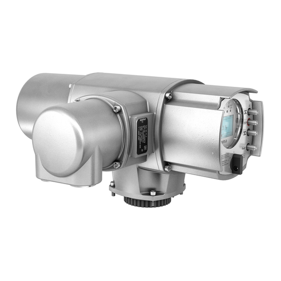
“Warning” marks activities or procedures which, if not carried out correctly, can affect the safety of persons or material. Short description AUMA actuators have a modular design. Motor and gearing are mounted in a common housing. The actuators are driven by an electric motor and controlled with the elec- tronic controls AUMATIC. -
Page 5: Transport And Storage
Masters are also called ‘active stations’ in the Profibus protocol. Slave devices such as AUMA Profibus DP actuators are peripheral devices. Typical slave devices are input/output devices, valves, actuators and measuring sensors. They do not have bus access, i.e. they may only acknowledge received messages or, at the request of a master, transmit messages to that master. -
Page 6: Basic Functions Of Profibus Dp
Device types DP Master class 2 (DPM2), e.g. programming / configuration devices. DP Master class 1 (DPM1), e.g. central controllers such as PLC, PC, ... DP slave, e.g. AUMA Profibus DP devices. Devices with binary or analogue inputs/outputs, actuators, valves. -
Page 7: Technical Data
1) The lifetime guaranteed by the manufacturer amounts to 2 million cycles. In case a higher number of cycles is to be expected, the use of thyristor units with nearly unlimited lifetime is recommended 2) Only partly possible in connection with process controller PID, please contact AUMA 3) Not possible in combination with PTC tripping device... - Page 8 Actuator controls AUMATIC AC 01.1 / ACExC 01.1 Profibus DP Operation instructions Local controls Standard: Selector switch LOCAL – OFF – REMOTE (lockable in all three positions) Push-buttons OPEN – STOP – CLOSE - RESET 5 indication lights: End position CLOSED and running indication CLOSE (yellow),...
- Page 9 Actuator controls AUMATIC AC 01.1 / ACExC 01.1 Operation instructions Profibus DP Electrical connections Standard: AUMA plug/socket connector with screw type connection Threads for cable glands: M-threads: 2 x M 25 x 1.5 / 4 x M 20 x 1.5...
- Page 10 Cable length for Non-intrusive version with MWG in the actuator max. 100 m. Requires separate data cable for MWG. If actuator and AUMATIC are separated at a later date the max. cable length is 10 m. 8) Only in combination with reversing contactors and AUMATIC AC 01.1 in enclosure protection IP 67 or IP 68...
-
Page 11: Design Aumatic Profibus Dp
Operation instructions Profibus DP Design AUMATIC Profibus DP With the AUMATIC Profibus DP, AUMA provides the ideal controls for the connection of multi-turn actuators of the type range SA and part-turn actua- tors of the type range SG to Profibus DP. -
Page 12: Electrical Connection
51.0 tions. In case the wiring diagram is not available, it can be obtained from Mains AUMA (state commission no. refer to name plate) or downloaded directly cable from the Internet (www.auma.com). 51.01... -
Page 13: Fitting Of The Connection Housing
Actuator controls AUMATIC AC 01.1 / ACExC 01.1 Operation instructions Profibus DP Fitting of the connection After mains connection: housing Insert the socket carrier (51.0) into the plug cover (50.0) and fasten it with screws (51.01). Clean sealing faces at the connection housing and the actuator housing. - Page 14 Actuator controls AUMATIC AC 01.1 / ACExC 01.1 Profibus DP Operation instructions Figure C-1: Connection board (standard) Figure C-2: Connection board (for overvoltage protection) Bus termination Bus termination Channel 1 Bus termination Channel 1 Channel 2 Figure C-3: Connection (standard)
-
Page 15: Mains And Bus Connection For Explosion-Proof Version
Actuator controls AUMATIC AC 01.1 / ACExC 01.1 Operation instructions Profibus DP 7.5.2 Mains and bus connection for explosion-proof version For version with FO (fibre optics) refer to separate operation instructions “AUMATIC ACExC 01.1 FO connection”. When working in potentially explosive areas, observe the European Standards EN 60079-14 “Electrical Installations in... - Page 16 Cross section max. 6 mm 6 mm 1.5 mm Material: Pin / socket carrier Araldite / Polyamide Araldite / Polyamide Araldite / Polyamide Contacts Brass (Ms) Brass (Ms) Brass (Ms) tin-plated 1) Suitable for copper wires. For aluminium wires contact AUMA.
-
Page 17: Bus Cables
Actuator controls AUMATIC AC 01.1 / ACExC 01.1 Operation instructions Profibus DP 7.5.3 Bus cables Only cables according to standard DIN 19245 or EN 50170-2, cable type A, may be used for Profibus DP wiring. A maximum of up to 32 Profibus devices may be connected in one segment. -
Page 18: Setting The Profibus Dp Address Via Local Controls
Actuator controls AUMATIC AC 01.1 / ACExC 01.1 Profibus DP Operation instructions Setting the Profibus DP address via local controls This clause only describes the setting of the actuator address (slave address). For further detailed instructions on the indication, operation and setting of the AUMATIC refer to the operation instructions of the actuator (multi-turn actuator SA(R) …... - Page 19 Actuator controls AUMATIC AC 01.1 / ACExC 01.1 Operation instructions Profibus DP Figure ENTER PASSWORD 0 * * * :EDIT C:ESC With the push-buttons the value of the selected position can be changed. To accept the input and move to the next digit, press push-button proceed until all password digits are entered.
-
Page 20: Commissioning With Controls
The parameterization is partly determined in the Profibus standard, e.g. a bit for switching bus monitoring on and off (watchdog). The AUMA Profibus DP controls can additionally receive up to 37 bytes of ‘user parameters’, in which AUMA specific parameters can be set. The AUMA specific parameters are divided into 34 parameters with 1 byte each per parameter.
Need help?
Do you have a question about the AUMATIC AC 01.1 and is the answer not in the manual?
Questions and answers