AUMA Aumatic ACExC 01.1 Operation Instructions Manual
Actuator controls.
Hide thumbs
Also See for Aumatic ACExC 01.1:
- Manual (112 pages) ,
- Operation instructions manual (88 pages) ,
- Short instructions (16 pages)

Related Manuals for AUMA Aumatic ACExC 01.1


Summary of Contents for AUMA Aumatic ACExC 01.1
- Page 1 Actuator controls AUMATIC AC 01.1 ACExC 01.1 DeviceNet Operation instructions Zertifikat-Registrier-Nr. 12 100/104 4269...
-
Page 2: Table Of Contents
Actuator controls AUMATIC AC 01.1 / ACExC 01.1 DeviceNet Operation instructions Scope of these instructions: These instructions are valid for multi-turn actuators of the type ranges SA(R) 07.1 – SA(R) 16.1 and SA(R)ExC 07.1 – SA(R)ExC 16.1 as well as for part-turn actuators of the type ranges SG 05.1 –... - Page 3 Appendix A EDS file Appendix B standard wiring diagram 22.1 Legend to standard wiring diagram Appendix C Proposed wiring diagrams Appendix D Literature references Appendix E Connection of the screen for AUMATIC ACExC 01.1 Index Addresses of AUMA offices and representatives...
-
Page 4: Safety Instructions
“Warning” marks activities or procedures which, if not carried out correctly, can affect the safety of persons or material. Short description AUMA actuators have a modular design. Motor and gearing are mounted in a common housing. The actuators are driven by an electric motor and controlled with the elec- tronic controls AUMATIC. -
Page 5: Transport And Storage
Actuator controls AUMATIC AC 01.1 / ACExC 01.1 Operation instructions DeviceNet Transport and storage Transport to place of installation in sturdy packing. Do not attach ropes or hooks to the handwheel for the purpose of lifting by hoist. Store in well-ventilated, dry room. Protect against floor dampness by storage on a shelf or on a wooden pallet. -
Page 6: Devicenet Cable
Actuator controls AUMATIC AC 01.1 / ACExC 01.1 DeviceNet Operation instructions DeviceNet cable The DeviceNet cable provides both the CAN data signal and the power supply for network and devices. The different system and device require- ments are cover by three cable types: Thick Cable, Thin Cable and Flat Cable. -
Page 7: Devicenet Communication
Actuator controls AUMATIC AC 01.1 / ACExC 01.1 Operation instructions DeviceNet node), or, if this is not possible, has to provide a suitable galvanic isolation within the device (device designation: isolated node). The AUMATIC with DeviceNet has a galvanic isolation within the device and can therefore also be called isolated node. -
Page 8: Protection Functions
Actuator controls AUMATIC AC 01.1 / ACExC 01.1 DeviceNet Operation instructions DeviceNet distinguishes between three types of objects: communication objects, system objects and application specific objects. Communication objects define the data exchanged via DeviceNet, they are also called connection objects. System objects define general DeviceNet specific data and function which are useful for most DeviceNet devices. -
Page 9: Technical Data
1) The lifetime guaranteed by the manufacturer amounts to 2 million cycles. In case a higher number of cycles is to be expected, the use of thyristor units with nearly unlimited lifetime is recommended 2) Only partly possible in connection with process controller PID, please contact AUMA 3) Not possible in combination with PTC tripping device... - Page 10 Additional thermal overload relay in the controls PTC tripping device in combination with PTC thermistors in the actuator motor Electrical connections Standard: AUMA plug/socket connector with screw type connection Threads for cable glands: M-threads: 5 x M 25 x 1.5 Pg-threads:...
- Page 11 Actuator controls AUMATIC AC 01.1 / ACExC 01.1 Operation instructions DeviceNet Further options for Non-intrusive version with MWG in the actuator Setting of limit and torque switching via local controls Electronic timer Start and end of stepping mode as well as ON and OFF time (1 up to 300 seconds) can be programmed individually for the directions OPEN and CLOSE.
- Page 12 Vibration resistance 1 g, from 10 Hz to 200 Hz according to IEC 60 068 Weight approx. 7 kg (including AUMA plug/ socket connector) Accessories Wall bracket AUMATIC mounted separately from the actuator, including plug/ socket connector. Connecting cables on request.
-
Page 13: Aumatic Devicenet Design
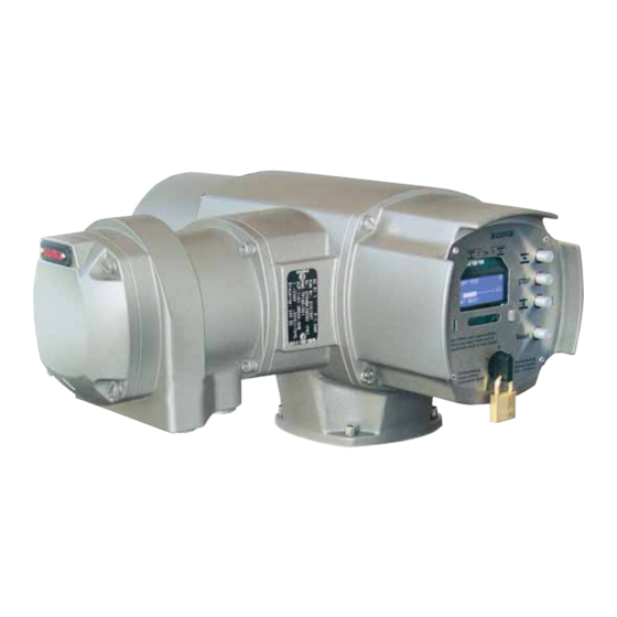
Actuator controls AUMATIC AC 01.1 / ACExC 01.1 Operation instructions DeviceNet AUMATIC DeviceNet design With the AUMATIC DeviceNet, AUMA offers the ideal controls for the connection of multi-turn actuators SA and part-turn actuators SG to DeviceNet. Figure C: AUMATIC DeviceNet... -
Page 14: Electrical Connection
Contacts Brass (Ms) Brass (Ms) gold-plated (option) 1) Suitable for copper wires. For aluminium wires it is necessary to contact AUMA. Remote position transmitter For the connection of remote position transmitters (potentiometer, RWG) screened cables must be used. AUMATIC on wall bracket The AUMATIC can also be mounted separately from the actuator on a wall bracket. -
Page 15: Fitting Of The Connection Housing
Actuator controls AUMATIC AC 01.1 / ACExC 01.1 Operation instructions DeviceNet Fitting of the connection After mains connection: housing Insert the socket carrier (51.0) into the plug cover (50.0) and fasten it with screws (51.01). Clean sealing faces at the connection housing and the actuator housing. Check whether O-ring is in good condition. - Page 16 Actuator controls AUMATIC AC 01.1 / ACExC 01.1 DeviceNet Operation instructions Figure D-4: Connection board (standard) Figure D-5: Connection board (for overvoltage protection) Bus termination channel 1 Bus termination Figure D-6: Connection diagram (standard) Figure D-7: Connection diagram (for overvoltage protection) from previous to next from previous...
-
Page 17: Mains And Bus Connection For Explosion-Proof Version
Actuator controls AUMATIC AC 01.1 / ACExC 01.1 Operation instructions DeviceNet Mains and bus connection for explosion-proof version When working in potentially explosive areas, observe the European Standards EN 60079-14 “Electrical Installations in Hazardous Areas” and EN 60079-17 “Inspection and Mainte- nance of Electrical Installations in Hazardous Areas”. - Page 18 6 mm 1.5 mm Material: Pin / socket carrier Araldite / Polyamide Araldite / Polyamide Araldite / Polyamide Contacts Brass (Ms) Brass (Ms) Brass (Ms) tin-plated 1) Suitable for copper wires. For aluminium wires it is necessary to contact AUMA.
-
Page 19: Bus Cables
Actuator controls AUMATIC AC 01.1 / ACExC 01.1 Operation instructions DeviceNet Bus cables Only cables conforming to the DeviceNet wire specification (www.odva.org) may be used for a DeviceNet network. The bus cable must be laid at a distance of at least 20 cm from other cables. It should be laid in a separate, conductive and earthed cable trunking. -
Page 20: Setting The Devicenet Address And The Baud Rate Via The Local Controls
Drop line Features: Trunk line with optional drop lines AUMA DeviceNet controls can be removed without interrupting the trunk line (the trunk line will remain connected in the bus connection) Up to 64 DeviceNet devices can be connected DeviceNet data signal and 24 V DC DeviceNet voltage supply in a single... - Page 21 Actuator controls AUMATIC AC 01.1 / ACExC 01.1 Operation instructions DeviceNet Select SETTINGS with push-button Figure MAIN MENU LANGUAGE / CONTRAST SETTINGS OPERATIONAL DATA Confirm the selection with SETTINGS Figure SETTINGS SET LIMIT SWITCHES SEATING MODE TORQUE Select DEVICE-NET1 by pushing several times: Figure SETINGS...
- Page 22 Actuator controls AUMATIC AC 01.1 / ACExC 01.1 DeviceNet Operation instructions Setting the baud rate: Confirm with push-button BAUDRATE SW.VALUE Figure EDIT M1M10 BAUDRATE SW.VALUE 125 KBAUD :EDIT C:ESC Change to the edit mode with Figure EDIT M1M10 F-10 BAUDRATE SW.VALUE 125 KBAUD :EDIT C:ESC...
-
Page 23: Further Parameters Of The Devicenet Interface
Actuator controls AUMATIC AC 01.1 / ACExC 01.1 Operation instructions DeviceNet Address 63 (default setting) should not be used since this is the default address for all DeviceNet devices. Use address 64 to activate the MAC ID setting via DeviceNet (in this case the DeviceNet address can be defined via Explicit Messages of the process control system, e.g. -
Page 24: Commissioning With Controls Introduction
The configuration is made using an electronic data sheet (EDS file = Elec- tronic Data Sheet, available at www.auma.com). Functions of the AUMATIC with DeviceNet The DeviceNet interface of the AUMATIC supports the following DeviceNet... -
Page 25: List Of Objects Available In The Aumatic
Actuator controls AUMATIC AC 01.1 / ACExC 01.1 Operation instructions DeviceNet 8.5.1 List of objects available in the AUMATIC Table 9 Object Class Class ID Instance IDs Messages Explicit Identity Object Message Router Object Explicit Explicit DeviceNet Object 100 – 107, Explicit &... -
Page 26: Poll I/O Data Interface Of The Aumatic
Actuator controls AUMATIC AC 01.1 / ACExC 01.1 DeviceNet Operation instructions Table 10: Addressing the parameters via configuration tool Parameters AUMATIC Display indications Setting via configuration tool Parameter designation Parameter value Value Address SELECTED SELECTED CONS. PATH STANDARD OUT Class ID 101 (65 hex) CONSUMED PATH STANDARD 1 AN. - Page 27 Actuator controls AUMATIC AC 01.1 / ACExC 01.1 Operation instructions DeviceNet Extended One Analog Input SELECTED PRODUCED PATH = 3 Data length = 8 byte Word 1 (actuator signals) Word 2 (E2 Feedback) E2 Feedback (0 – 1 000 per mil) Word 3 (extended) Word 4...
- Page 28 Actuator controls AUMATIC AC 01.1 / ACExC 01.1 DeviceNet Operation instructions Enhanced Input SELECTED PRODUCED PATH = 5 Data length = 14 byte Word 1 (actuator signals) E2 Feedback (0 – 1 000 per mil) Word 2 (E2 Feedback) Word 3 (extended) Wort 4 Analogue input 1 (0 –...
- Page 29 Actuator controls AUMATIC AC 01.1 / ACExC 01.1 Operation instructions DeviceNet Process Input Data 2 SELECTED PRODUCED PATH = 7 Data length = 14 byte Byte 1 Byte 2 (Logical (Actuator signals) signals) Byte 4 Byte 3 E2 Feedback 1 (0 – 1 000 per mil) high byte E2 Feedback 1 (0 –...
- Page 30 Actuator controls AUMATIC AC 01.1 / ACExC 01.1 DeviceNet Operation instructions Process Input Data 3 SELECTED PRODUCED PATH = 8 Data length = 17 byte Byte 1 Byte 2 (Logical sig- (Actuator nals) signals) Byte 4 Byte 3 E2 Feedback 1 (0 – 1 000 per mil) high byte E2 Feedback 1 (0 –...
-
Page 31: Detailed Description Of The Input Data
Actuator controls AUMATIC AC 01.1 / ACExC 01.1 Operation instructions DeviceNet 9.1.1 Detailed description of the input data The input data are described below in alphabetical order. Designation Description (if there is no further explanation in the text, the description for bit value = 1 applies) Collective signal: contains the result of a disjunction (or operation): Actuator moving Running LOCAL, Running REMOTE, Running with handwheel... - Page 32 Actuator controls AUMATIC AC 01.1 / ACExC 01.1 DeviceNet Operation instructions Designation Description (if there is no further explanation in the text, the description for bit value = 1 applies) Indicates that the position transmitter has not been adjusted to the limit end positions yet. To ad- No internal feedback just the actuator: Move the actuator manually to the end positions OPEN or CLOSED via the push-buttons on the local controls.
-
Page 33: Description Of The Output Data
Actuator controls AUMATIC AC 01.1 / ACExC 01.1 Operation instructions DeviceNet Description of the output data Standard Output SELECTED CONSUMED PATH = 1 Data length = 4 byte Word 1 (commands) Word 2 E1 setpoint (0 – 1 000 per mil) (E1 setpoint) 1) With the bits 0, 1 and 4, the operation commands are transmitted to the actuator. -
Page 34: Detailed Description Of The Output Data
Actuator controls AUMATIC AC 01.1 / ACExC 01.1 DeviceNet Operation instructions Continuation of Process Output Byte 5 Byte 6 (Additional (reserved) commands) Reserved Reserved Byte 7 Byte 8 3) See external change-over of the communication channel (page 48) 4) See release function of the local controls (page 41) 9.2.1 Detailed description of the output data The output data (consumed data) are described below in alphabetical order. -
Page 35: Operation Parameters Of The Actuator
Actuator controls AUMATIC AC 01.1 / ACExC 01.1 Operation instructions DeviceNet 10. Operation parameters of the actuator Explicit Messages are used for programming the AUMATIC via DeviceNet. With the EDS file (Electronic Data Sheet), the AUMATIC offers access to the following parameters via DeviceNet: Parameter access to the DeviceNet net data (the meaning of the parameters is described in detail in the operation instructions to the actuator “Multi-turn actuators SA .../part-turn actuators SG ... - Page 36 Actuator controls AUMATIC AC 01.1 / ACExC 01.1 DeviceNet Operation instructions Parameter s for setting the application functions of the AUMATIC (the meaning of the parameters is described in detail in the operation instructions to the actuator “Multi-turn actuators SA .../part-turn actuators SG ... with AUMATIC AC“) ID in Description Class...
- Page 37 Actuator controls AUMATIC AC 01.1 / ACExC 01.1 Operation instructions DeviceNet ID in Description Class Instance Attribute Note EDS file Pos.8 Behaviour Pos.8 Selector Switch Pos.8 Control Stepping Mode Parameters for setting the stepping mode Direction Open On Time Open Off Time Open Start Step Open Stop Step Open...
- Page 38 Actuator controls AUMATIC AC 01.1 / ACExC 01.1 DeviceNet Operation instructions Access to the parameters of the AUMATIC AC 01.1 via Explicit DeviceNet Messages is usually gained using the EDS file (Electronic Data Sheet) in combination with a configuration tool, e.g. RSNetWorx by Allen-Bradley. In the EDS file, the parameters are defined with their Class ID, Instance ID and Attribute ID as well as the permissible minimum and maximum values.
-
Page 39: Description Of Actuator Functions
Actuator controls AUMATIC AC 01.1 / ACExC 01.1 Operation instructions DeviceNet 11. Description of actuator functions 11.1 Operation commands for OPEN / CLOSE operation Operation commands are determined by operation command bits and the nominal value (setpoint) of the data output. Only one command bit may be set at any given time. -
Page 40: Positioner
Actuator controls AUMATIC AC 01.1 / ACExC 01.1 DeviceNet Operation instructions 11.2 Positioner The positioner is activated via the bit ‘Remote SETPOINT’. The positioner is a three-position-controller. Via the ‘NOMINAL’ position (setpoint) in the data output, the nominal value of the position is transmitted to the actuator as nominal variable. -
Page 41: Release Function Of The Local Controls (Option)
Actuator controls AUMATIC AC 01.1 / ACExC 01.1 Operation instructions DeviceNet 13. Release function of the local controls (option) The AUMATIC can be set in such a way that the AUMATIC-internal selector switch position is additionally determined by 3 bits in the process represen- tation output. -
Page 42: Additional Control Inputs (Option)
Actuator controls AUMATIC AC 01.1 / ACExC 01.1 DeviceNet Operation instructions 14. Additional control inputs (option) The digital and analogue input signals of the DeviceNet interface can be interpreted as additional operation commands. Through this, an additional operation command channel is available (four digital inputs or one analogue 0/4 –... - Page 43 Actuator controls AUMATIC AC 01.1 / ACExC 01.1 Operation instructions DeviceNet OPEN CLOSE ESD Conventional control is possible in the open-close duty (OPEN-CLOSE-EMERGENCY). The analogue inputs ANIN1 and ANIN2 have no function. In this configuration, the EMERGENCY function has the highest priority. The polarity of the EMERGENCY input is identical to the standard AUMATIC version (equipped with an I/O interface).
-
Page 44: Combination Fieldbus / Standard Interface (Option)
Actuator controls AUMATIC AC 01.1 / ACExC 01.1 DeviceNet Operation instructions 15. Combination fieldbus / standard interface (option) The AUMATIC can also be equipped with an additional interface. By this, an additional operation command channel (digital inputs or an analogue 0/4 –... -
Page 45: Emergency Stop Function (Option)
Actuator controls AUMATIC AC 01.1 / ACExC 01.1 Operation instructions DeviceNet The EMERGENCY function is defined via the parameters for the operation mode EMERGENCY. Refer to the operation instructions to the actuator (multi-turn actuator SA(R) … / part-turn actuator SG . . . with AUMATIC AC . . .). If the actuator is to be operated via fieldbus or the inputs of the I/O, the selector switch has to be in position “REMOTE”. - Page 46 Actuator controls AUMATIC AC 01.1 / ACExC 01.1 DeviceNet Operation instructions After having unlocked the EMERGENCY STOP button, a possibly active operation command will not immediately be re-activated, but only after a confirmation by the user has been given which resets the EMERGENCY STOP status.
-
Page 47: Redundant Bus Connection With Component Redundancy (Option)
Actuator controls AUMATIC AC 01.1 / ACExC 01.1 Operation instructions DeviceNet 17. Redundant bus connection with component redundancy (option) The AUMATIC can be equipped with a second (redundant) DeviceNet inter- face. In this version, communication to the actuator can be established simultaneously through both DeviceNet interfaces. -
Page 48: External Change-Over Of The Communication Channels
Actuator controls AUMATIC AC 01.1 / ACExC 01.1 DeviceNet Operation instructions 17.2 External change-over of the communication channels A certain communication channel can be selected externally via the change-over bits channel 1 and channel 2 in the process representation output (page 34). Bit 5 Bit 4 Designation... -
Page 49: Indication And Programming Of The Aumatic
Actuator controls AUMATIC AC 01.1 / ACExC 01.1 Operation instructions DeviceNet 18. Indication and programming of the AUMATIC 18.1 Software parameters of the DeviceNet interface To go to the display indications and the software parameters: Set selector switch to position OFF (0), figure M. Switch on supply voltage. - Page 50 Actuator controls AUMATIC AC 01.1 / ACExC 01.1 DeviceNet Operation instructions Standard Min/ Note Subgroup Parameter Valuetext value name menu M1MX0 3 Baud rate; change via local con- M1M DEVICE- BAUDRATE 125KBAUD trols possible, use PGM MODE to NET 1 SW.VALUE 250KBAUD activate the baud rate setting via...
- Page 51 Actuator controls AUMATIC AC 01.1 / ACExC 01.1 Operation instructions DeviceNet Standard Min/ Note Subgroup Parameter Valuetext value name menu M1M06 6 Connection path for data which DEVICE- SELECTED PRO- STANDARD are 'produced' by the actuator NET 1 DUCED PATH INPUT (refer also to above description of EXTENDED...
-
Page 52: Description Via Devicenet Interface
Actuator controls AUMATIC AC 01.1 / ACExC 01.1 DeviceNet Operation instructions 19. Description via DeviceNet interface Figure N: DeviceNet interface Table 12: DIP switch S1: Configuration of the DeviceNet interface Only one DeviceNet interface available S1-1 1st DeviceNet interface Two DeviceNet interfaces available 2nd DeviceNet interface: ON S1-2... -
Page 53: Assignment Of The Customer Inputs Of The Devicenet Interface (Option)
Actuator controls AUMATIC AC 01.1 / ACExC 01.1 Operation instructions DeviceNet 19.1 Assignment of the customer inputs of the DeviceNet interface (option) This plug provides pins for 4 digital customer inputs and 2 analogue customer inputs. Table 13: Digital inputs (galvanically isolated) Description R1: digital input 1 V 21... -
Page 54: Trouble Shooting And Corrective Actions
Actuator controls AUMATIC AC 01.1 / ACExC 01.1 DeviceNet Operation instructions 20. Trouble shooting and corrective actions 20.1 Optical signals during operation Figure O: DeviceNet interface LED ’SYSTEM OK’ (V7)(green) Shows the correct voltage supply to the DeviceNet board. Is continuously illuminated: Voltage connected to DeviceNet interface. Is blinking: Microcontroller defective. -
Page 55: Status Indications In The Display
20.3 DeviceNet diagnosis indication in the display The information contained in the diagnosis indication (Group ) is only provided for the AUMA service and for enquiries in the factory. In the subgroup DR,DS,DT,DU,DV status information can be requested of DeviceNet. -
Page 56: Offline Connection Set Of The Aumatic
Actuator controls AUMATIC AC 01.1 / ACExC 01.1 DeviceNet Operation instructions Menu Abbreviation Note inthe display Module status of the DeviceNet interface 1 DN1 MODULE STATUS No DeviceNet voltage supply available NOT POWERED DEVICE OPERATIONAL AUMATIC is in the normal operation status (optimum status) AUMATIC is in the standby status and requires a new DeviceNet interface con- DEVICE IN STANDBY figuration due to missing, incomplete or incorrect settings. -
Page 57: Actuator Can Not Be Controlled Via Devicenet
Actuator controls AUMATIC AC 01.1 / ACExC 01.1 Operation instructions DeviceNet 20.6 Actuator can not be controlled via DeviceNet Start Change to the diagnosis page DT ‘DN1 BUS STATUS’ (see subclause 20.3) In the diagnosis page DT ‘Dn1 BUS STATUS’ ‘DATA EX’... - Page 58 Actuator controls AUMATIC AC 01.1 / ACExC 01.1 DeviceNet Operation instructions Check DeviceNet board Check LED ‘SYSTEM OK’ (V7) on DeviceNet board: (V7) continuously illuminated (V7) not illluminated (V7) blinking Voltage supply of the DeviceNet board is not DeviceNet board defective DeviceNet board supplied with voltage is o.k.
-
Page 59: Appendix A Eds File
Actuator controls AUMATIC AC 01.1 / ACExC 01.1 Operation instructions DeviceNet 21. Appendix A EDS file The EDS file can be downloaded from the Internet: www.auma.com... -
Page 60: Appendix B Standard Wiring Diagram
Actuator controls AUMATIC AC 01.1 / ACExC 01.1 DeviceNet Operation instructions 22. Appendix B standard wiring diagram Legend page 61 Original wiring diagram and legend are delivered together with the actuator. -
Page 61: Legend To Standard Wiring Diagram
Actuator controls AUMATIC AC 01.1 / ACExC 01.1 Operation instructions DeviceNet 22.1 Legend to standard wiring diagram... -
Page 62: Appendix C Proposed Wiring Diagrams
Actuator controls AUMATIC AC 01.1 / ACExC 01.1 DeviceNet Operation instructions 23. Appendix C Proposed wiring diagrams... - Page 63 Actuator controls AUMATIC AC 01.1 / ACExC 01.1 Operation instructions DeviceNet...
- Page 64 Actuator controls AUMATIC AC 01.1 / ACExC 01.1 DeviceNet Operation instructions...
-
Page 65: Appendix D Literature References
ISBN 3-446-21776-2 4. Open DeviceNet Vendors Association ODVA www.odva.org 25. Appendix E Connection of the screen for AUMATIC ACExC 01.1 The screen of the fieldbus cable should be largely connected with the respective threads. Recommended threads, e.g. WAZU-EMV/EX by Hugro (see... - Page 66 Actuator controls AUMATIC AC 01.1 / ACExC 01.1 DeviceNet Operation instructions Notes...
-
Page 67: Index
Actuator controls AUMATIC AC 01.1 / ACExC 01.1 Operation instructions DeviceNet Index Actuator functions Mains connection Technical data AUMA plug/ socket connector Maintenance Termination resistors AUMATIC design Modulating duty Thyristors Torque switching Transport Bus access Name plate Trouble shooting and... -
Page 68: Addresses Of Auma Offices And Representatives
D - 79373 Müllheim D - 73747 Ostfildern +49 (0)7631/809-0 +49 (0)711 / 34803 0 +49 (0)7631/809 250 +49 (0)711 / 34803 34 riester@auma.com riester@wof.auma.com Zertifikat-Registrier-Nr. 12 100/104 4269 www.auma.com www.auma.com For detailed information on AUMA products refer to the Internet: Y003.247/003/en/1.05 www.auma.com...
Need help?
Do you have a question about the Aumatic ACExC 01.1 and is the answer not in the manual?
Questions and answers