Table of Contents
Advertisement
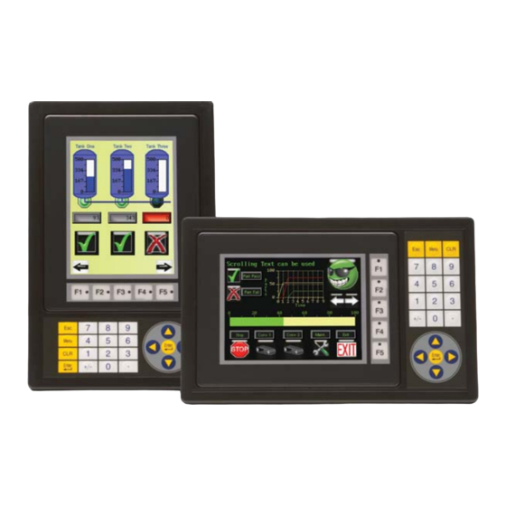
4-inch and 6-inch Color Micro-Graphic Panels
®
Hardware User Manual
EA1-TCL-M
C-more 6" Color Micro-Graphic Panel
shown in Portrait Mode
C-more 6" Color Micro-Graphic Panel
shown in Landscape Mode
C-more 4" Color Micro-Graphic Panel
shown in Landscape Mode
C-more 6" Color Micro-Graphic Panel Installed in a
21-button Portrait Keypad Bezel EA-MG6-BZ2P
C-more 6" Color Micro-Graphic Panel Installed in a
20-button Landscape Keypad Bezel EA-MG6-BZ2
Advertisement
Table of Contents


Need help?
Do you have a question about the C-more EA1-T4CL and is the answer not in the manual?
Questions and answers