Otto Bock Avantgarde CV Service Manual
Hide thumbs
Also See for Avantgarde CV:
- Instructions for use manual (32 pages) ,
- Instructions for use manual (36 pages) ,
- Service manual (64 pages)

Related Manuals for Otto Bock Avantgarde CV


Summary of Contents for Otto Bock Avantgarde CV
- Page 1 Avantgarde CV / CS / CLT Service Manual ..................© Otto Bock · 647G690=EN-01-1102...
- Page 2 02/2011...
-
Page 3: Table Of Contents
Table of contents Table of contents Introduction ................................Foreword ..............................Support ................................ Product overview ............................Safety ..................................Explanation of warning symbols ......................... General Safety Instructions ........................Service Work ................................. Instructions for Adjustment ........................Required Tools and Accessories ....................... Special features of the Avantgarde CLT .................... - Page 4 Table of contents 3.6.3.5 Replacing the Tube Foot Rest Mounting ................Assembly C: Seat ............................3.7.1 Replacing the Standard/Business Seat Upholstery ................. 3.7.2 Replacing the Seat Upholstery, Adaptable ..................3.7.3 Cleaning the Seat Upholstery ......................3.7.4 Cleaning the Standard Seat Cushion .....................
- Page 5 Table of contents 3.11.6.4 Adjusting the Quick-Release Axle ..................3.11.6.5 Retrofitting the Tetra Axle ....................3.12 Assembly H: Wheel Lock/Brake ........................ 3.12.1 Adjusting the Knee Lever Wheel Lock/Drum Brake ................. 3.12.2 Replacing the Knee Lever Wheel Lock ................... 3.12.3 Replacing the Brake Block ......................
-
Page 6: Introduction
Instructions for Use (qualified person Instructions for Use (User) nel) Avantgarde CV/CS/CLT 647G568=* 647G689=* 1.2 Support Your national Otto Bock team will be happy to answer any technical questions. The contact addresses and telephone numbers can be found on the back of the service manual. -
Page 7: Product Overview
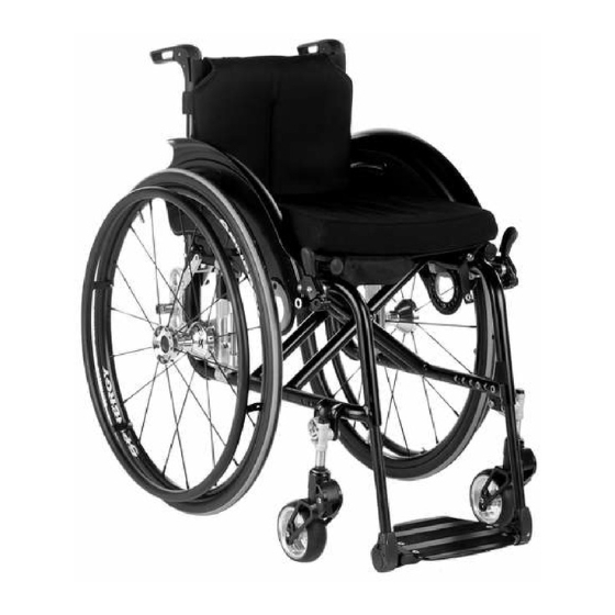
Introduction 1.3 Product overview Avantgarde CS Maximum load (in combination with double cross-brace): 140 kg Thanks to its closed frame geometry, the Avantgarde CS allows very rigid and sporting use. 1 Seat/seat pad 9 Rear wheel with push ring 2 Side panel 10 Quick-release axle release button 3 Back/back upholstery 11 Double cross-brace... - Page 8 Maximum load (in combination with double cross-brace): 140 kg Thanks to its frame geometry, the Avantgarde CV offers precise leg guidance with the possibility of swinging away and removing the foot rests. When the foot rests are removed, the upright frame front section allows the wheelchair to be manoeuvred close to objects.
-
Page 9: Safety
Safety Avantgarde CLT Maximum load (in combination with double cross-brace): 100 kg The Avantgarde CLT is the weight-optimised sports version for particularly active users. In the version CLT "welded", subsequent modification of the wheel position and back height was sacrificed in favour of saving additional weight. 1 Seat/seat pad 9 Rear wheel with push ring 2 Side panel... -
Page 10: General Safety Instructions
Service Work 2.2 General Safety Instructions INFORMATION Read the service manual before starting work. Familiarise yourself with the product's functions before use. If you are not familiar with the product, read the service manual before performing the inspection. If a service manual is not available, request it from the manufacturer (see the overview of all Otto Bock branches "Otto Bock Worldwide"). -
Page 11: Required Tools And Accessories
Service Work All instructions concerning the adjustment of the parts installed are included in the Instructions for Use (qualified per sonnel) – order number 647G585. 3.2 Required Tools and Accessories The following tools are required in order to perform the service work: •... -
Page 12: Assembly A: Frame
Service Work 1. Function/setting 2. Inspected for dam 3. Screw connections (depending on equipment) age/deformation inspected Foot rest accessories Heel strap Seat Cross-brace Seat upholstery Seat cushion Back / push handles Back upholstery Back tubes Angle adjustment Push handles Side panels Height setting Swivel mechanism Removability... -
Page 13: Replacing The Rear Frame Part
Service Work 6) Remove the front part of the frame upward (see Fig. 6). 7) Remove all parts (knee lever brake, supports) installed on the frame. 8) To reassemble, perform these steps in reverse order. Tighten the frame tubes with 23 Nm. 3.5.1.2 Replacing the Rear Frame Part 1) Remove the rear wheels and flip up the foot plates. -
Page 14: Replacing The Cross-Brace/Cross-Brace Bracket
Service Work 3.5.1.3 Replacing the Cross-Brace/Cross-Brace Bracket INFORMATION The frame components are no longer connected when the crossbrace is removed. Carefully lay the frame compon ents on the work surface one after another. 1) Remove both front parts of the frame (see Page 12). 2) Unscrew the cross-brace centre screw and remove (see Fig. -
Page 15: Replacing The Joint Tubes
Service Work 3.5.1.4 Replacing the Joint Tubes 1) Remove the front part of the frame (see Page 12). 2) Unscrew the rear wheel adapter and remove (see Page 12). 3) Remove the cross-brace (see Page 14). 4) Remove/replace the joint tubes (see Fig. 15). 5) To reassemble, perform these steps in reverse order. -
Page 16: Retrofitting The Vertical Accessory Mount
Service Work 3.5.2 Retrofitting the Vertical Accessory Mount INFORMATION The vertical accessory mount and the frame accessories cannot be installed on the welded Avantgarde CLT. The vertical accessory mount is required for the installation of the anti-tipper and the transport wheels (see Fig. 18, item 1). -
Page 17: Installation / Adjustment Of The Anti-Tipper
Service Work 3.5.3 Installation / adjustment of the anti-tipper CAUTION Incorrect fitting of anti-tipper / missing anti-tipper Risk of tipping of the user to the rear ► Check correct installation and adjustment of the anti-tipper: ► Depending on the adjustment of the chassis, the wheelchair centre of gravity and the experience of the user, an anti-tipper may be necessary. -
Page 18: Adjustment Of The Anti-Tipper
Service Work 3.5.3.2 Adjustment of the anti-tipper Height adjustment of the anti-tipper 1) Unscrew the mounting screw of the anti-tipper tube from the accessory mount (see Fig. 22, item 2). 2) Move the anti-tipper tube in the vertical accessory mount. 3) Bolt down the anti-tipper tube. -
Page 19: Replacing Anti-Tipper Rollers
Service Work 3.5.3.4 Replacing Anti-Tipper Rollers The replacement is made without tools by pulling out the plug-in tube. 3.5.4 Retrofitting the Transport Wheels CAUTION Incorrect adjustment of the transport wheels Risk of falling, tipping of the user ► Align the transport wheels to the rear while installing. ►... -
Page 20: Retrofitting The Tip-Assist
Service Work 3.5.6 Retrofitting the Tip-Assist 1) Unscrew the mounting screw on the accessory mount clamp (see Fig. 33). 2) Insert the tip-assist true to side (see Fig. 34). 3) Tighten the clamp's mounting screw to 8 Nm. 3.5.7 Retrofitting the Crutch Holder ►... -
Page 21: Assembly B: Footrest
Service Work 3.6 Assembly B: Footrest 3.6.1 Adjusting the Foot Rests/Tube Foot Rest/Foot Plates All instructions concerning the adjustment of the foot rests are included in the Instructions for Use (qualified personnel) – order number 647G585. 3.6.2 Replacement Work on the CV Model 3.6.2.1 Replacing the Foot Rest 1) Open the calf strap or pull it off the retaining lug on the swivel segment. -
Page 22: Replacing The Foot Plate
Service Work 3.6.2.3 Replacing the Foot Plate 1) Remove the foot rest. 2) Unscrew the size 4 Allen head screws on the angle adjustment (see Fig. 43). 3) Replace the foot plate. 4) To reassemble, perform these steps in reverse order. Tighten the Allen head screw to 10 Nm. 3.6.2.4 Replacing the Pivot Bearing 1) Remove the foot rest. -
Page 23: Replacing The Locking Device
Service Work 3.6.2.5 Replacing the Locking Device 1) Remove the foot rest. 2) Unscrew the size 4 Allen head screw on the locking device (see Fig. 45). 3) Remove/replace the locking device. 4) To reassemble, perform these steps in reverse order. Tighten the Allen head screw to 5 Nm. 3.6.2.6 Retrofitting the Heel Strap 1) Remove the foot rest. -
Page 24: Replacing The Calf Pads
Service Work 3) Insert the Allen head screw. 4) Tighten the Allen head screw to 8 Nm. 3.6.2.7.3 Replacing the Calf Pads 1) Unscrew the calf pad with retaining plate from the foot rest (see Fig. 50). 2) Unscrew the calf pad from the retaining plate (see Fig. 51). 3) Install the new calf pad with retaining plate on the foot rest. -
Page 25: Replacement Work On The Cs/Clt Model
Service Work 3.6.3 Replacement Work on the CS/CLT Model 3.6.3.1 Replacing the Foot Rest Bar 1) Unscrew/remove the size 5 Allen head screw on the inside of the front frame (see Fig. 53). 2) Remove and replace the foot rest bar (see Fig. 54). 3) The foot rest bar must be pushed at least 60 mm into the swivel segment. -
Page 26: Replacing The Tube Foot Rest Mounting
Service Work 3.6.3.5 Replacing the Tube Foot Rest Mounting 1) Unscrew the size 3 Allen head screw on the tube foot rest mounting (see Fig. 60). 2) Remove/replace the tube foot rest mounting. 3) Tighten the Allen head screw on the tube foot rest mounting to the point that flipping up and down without clear ance is possible. -
Page 27: Replacing The Seat Upholstery, Adaptable
Service Work 3.7.2 Replacing the Seat Upholstery, Adaptable 1) Slightly fold the wheelchair and remove the seat cushion. 2) Remove the seat pad. 3) Remove the protective cap (see Fig. 64). 4) Remove the seat upholstery from the cross-brace (see Fig. 65). 5) Remove/replace the upholstery bar (see Fig. -
Page 28: Cleaning The Seat Upholstery
Service Work 3.7.3 Cleaning the Seat Upholstery 1) Remove the seat upholstery. 2) Clean the seat upholstery with regular mild household detergent. 3) Reinstall the seat upholstery. 3.7.4 Cleaning the Standard Seat Cushion 1) Open the zipper and remove the foam core. 2) Clean the seat cushion according to the attached care label. -
Page 29: Retrofitting The Telescoping Push Handles
Service Work 3.8.1.2 Retrofitting the Telescoping Push Handles 1) Remove the old push handle. 2) Insert the telescoping push handle into the back tube (see Fig. 72). 3) In the upper hole screw the clamping lever onto the clamping lever slide block (see Fig. 73). 3.8.1.3 Retrofitting the Height-Adjustable Push Handles 1) Remove the old push handle. -
Page 30: Retrofitting The Folding Push Handles
Service Work 3.8.1.4 Retrofitting the Folding Push Handles 1) Remove the old push handle. 2) Remove the back pad. 3) For adaptable back upholstery: Open/remove the uppermost strap. 4) Insert the folding push handle into the back tube and bolt down the 2 size 5 Allen head screws (see Fig. 76). 5) For adaptable back upholstery: Mount the uppermost strap on the push handle and secure with hook-and-loop fastener (see Fig. -
Page 31: Replacing The Back Upholstery, Adaptable
Service Work 3) Remove/replace the back upholstery (see Fig. 80). 4) To reassemble, perform these steps in reverse order. 3.8.2.2 Replacing the Back Upholstery, Adaptable 1) Remove the push handles. 2) Remove the side panels. 3) Remove the back pad. 4) Open the uppermost strap and remove/replace (see Fig. -
Page 32: Replacing The Angle-Adjustable Back Tubes
Service Work 3.8.4 Replacing the Angle-Adjustable Back Tubes CAUTION Missing anti-tipper Risk of tipping of the user to the rear ► When using the 30° backrest angle with short wheelbase, two anti-tippers (one on each side) and with long wheelbase at least one anti-tipper must be fitted and activated. ►... -
Page 33: Assembly E: Side Panels
Service Work 3.9 Assembly E: Side Panels 3.9.1 Replacement Work on the Standard Side Panel/Clothing Protector 3.9.1.1 Replacing the Standard Side Panel/Clothing Protector 1) Remove the rear wheel. 2) At the back tube unscrew the size 5 Allen head screw from the side panel (see Fig. 89). 3) Unscrew the mounting screw on the adjustment disc and remove the cover of the adjustment disc (see Fig. -
Page 34: Replacing The Side Panel Mounting
Service Work 3.9.1.2 Replacing the Side Panel Mounting 1) Remove the size 5 Allen head screw on the adjustment disc (see Fig. 94, item 1). 2) Unscrew the size 4 Allen head screw on the slide block (see Fig. 91). 3) Remove/replace the side panel mounting (see Fig. -
Page 35: Replacing The Side Panel Mounting
Service Work 3.9.2.2 Replacing the Side Panel Mounting 1) Remove the desk side panel (see Fig. 99). 2) Unscrew the size 3 Allen head screw (see Fig. 100). 3) Remove/replace the side panel mounting. 4) To reassemble, perform these steps in reverse order. Tighten the Allen head screw to 5 Nm. 3.9.2.3 Replacing the Seat Tube Support For the replacement see Page 15. -
Page 36: Replacing The Pivot Pin
Service Work 3.9.2.5 Replacing the Pivot Pin 1) Remove the side panel. 2) Unscrew the 2 Phillips head screws on the pivot pin (see Fig. 102). 3) Remove/replace/bolt down the pivot pin. 3.9.2.6 Replacing the Strut 1) Remove the desk side panel. 2) Release the strut lock. -
Page 37: Adjusting The Caster Wheel Journal Angle
Service Work 3.10.2 Adjusting the Caster Wheel Journal Angle The threaded axle in the caster wheel adapter should be perpendicular to the ground to ensure optimum rolling beha viour of the wheelchair. The caster wheel adapter permits a continuous adjustment of this angle. 1) Remove the protective cap. -
Page 38: Replacing/Changing The Installation Position Of The Caster Wheels
Service Work 3.10.3 Replacing/Changing the Installation Position of the Caster Wheels INFORMATION Observe the seat height table in the "Technical Data". INFORMATION Replace the caster wheels if cracks are visible in the material or if the material is damaged. 1) Unscrew the screw connection of the threaded axle (see Fig. 113). 2) Remove the threaded axle/spacers (see Fig. -
Page 39: Replacing The Caster Fork
Service Work 3.10.4 Replacing the Caster Fork 1) Loosen/remove the size 19 hex nut inside the caster fork. 2) Remove the caster fork from the threaded bolt (caster axle) and replace (see Fig. 117). 3) Set the caster fork onto the threaded bolt. 4) Retighten the hex nut with 25 Nm. -
Page 40: Retrofitting The Caster Wheel Adapter For High/Low Seat Heights In The Front
Service Work 3.10.7 Retrofitting the Caster Wheel Adapter for High/Low Seat Heights in the Front 1) Unscrew/remove the caster head mounting on the frame (2x size 6 Allen head screws) (see Fig. 107). 2) Remove the caster head adapter and the caster head (see Fig. 108). 3) Position the new caster head adapter on the frame: →... -
Page 41: Assembly G: Rear Wheels
Service Work 3.11 Assembly G: Rear Wheels 3.11.1 Adjusting the Rear Wheels/Rear Wheel Adapters INFORMATION If the rear wheel size is changed, then the knee lever wheel lock must be readjusted as well (see section "Adjusting the wheel lock"). INFORMATION Changing the rear wheel position also changes the angle between the caster axles and the ground. -
Page 42: Installing The Fitting
Service Work 3.11.2.2 Installing the Fitting The rear wheel can be installed at 12 height positions in the rear wheel adapter. 1) Slightly loosen the nuts on both sides of the fitting (see Fig. 129, see Fig. 130). 2) Pull the camber washers apart until the fitting can be moved (see Fig. 131). 3) Move the fitting together with the nuts and camber washers into the desired position. -
Page 43: Shock Absorber System
Service Work 3.11.3 Shock Absorber System 3.11.3.1 Retrofitting the Shock Absorber The shock absorber system is clamped to the frame and is continuously adjustable as a result. 1) Remove the rear wheel adapter, standard (see Page 41). 2) Pre-install the upper shell on the shock absorber (see Fig. 133): →... -
Page 44: Installing The Fitting
Service Work 3.11.3.2 Installing the Fitting The rear wheel can be installed at 3 height positions on the shock absorber. 1) Loosen the nuts on both sides of the fitting (see Fig. 137, item 1). 2) Remove and change the installation position of the fitting. 3) Before installing the fitting, position the camber washers offset from one another (for 0°... -
Page 45: Installing The Fitting
Service Work 3.11.4.2 Installing the Fitting For the installation of the fitting see the section entitled "Shock Absorber System > Installing the Fitting". 3.11.5 Changing the Rear Wheel Camber Instructions for adjusting/changing the rear wheel camber are included in the Instructions for Use (qualified personnel) –... -
Page 46: Tensioning The Spokes/Adjusting The Out-Of-Round
Service Work 3) Tightly bolt the push rings onto the rim in narrow or wide installation position. 4) Completely reinstall the tyre. 3.11.6.3 Tensioning the Spokes/Adjusting the Out-of-Round Tensioning the spokes 1) Completely remove the tyre (see Fig. 145). 2) Check the spokes' tension by shaking/moving the spokes. 3) If necessary, carefully adjust the tension of the spokes with spoke tensioner. -
Page 47: Assembly H: Wheel Lock/Brake
Service Work 3.12 Assembly H: Wheel Lock/Brake 3.12.1 Adjusting the Knee Lever Wheel Lock/Drum Brake All instructions concerning the adjustment of the wheel lock/brake are included in the Instructions for Use (qualified personnel) – order number 647G585. 3.12.2 Replacing the Knee Lever Wheel Lock CAUTION Inadequate braking function of the knee lever wheel lock Risk of accidents, falling... -
Page 48: Replacing The Brake Block
Service Work 5 mm 3.12.3 Replacing the Brake Block 1) Unscrew the Allen head screw on the brake block (see Fig. 152). 2) Remove/replace the brake block. 3) Tighten the screw connection with 6 Nm. 3.12.4 Retrofitting the Wheel Lock Lever Extension 1) Remove the wheel lock handle from the knee lever wheel lock (see Fig. -
Page 49: Adjusting The Drum Brake
Service Work Installing the brake handles / Bowden cables 1) Install the brake handles on the back tubes (Phillips head screws; Retrofitting the Drum Brake [], similar to figure). 2) Route the Bowden cables from the brake handles to the brake drums. Make sure to prevent that scraping noises can develop. -
Page 50: Other Accessories
Appendices 3.13 Other Accessories 3.13.1 Retrofitting a Lap Belt ► Tighten the lap belt screws on the back rest tube to 7 Nm. The lap belt mounting point is the upper free hole at the rear part of the frame. 3.13.2 Retrofitting a Tray The tray can be attached to the standard/height-adjustable desk side panel: 1) Remove the protective foil from the tray. - Page 51 83.5 With wheelbase extension: Rear axle position +9.5 cm. For CLT Ultra model: Rear axle position -2 cm. Avantgarde CV/CS/CLT – Overall width with rear wheel with hollow rim (in cm) Seat width Side panels Standard and Clothing protector Desk side panel with armrest, height-adjustable 50.5...
- Page 52 Short lower leg length 16–31 Lower leg length 30–55 Avantgarde CV/CS/CLT – Front seat height (in cm) The front seat height depends on the selected wheel size, front wheel fork and mounting position. Front wheel with front Adjustment range wheel fork, short...
- Page 53 Appendices Avantgarde CS/CV/CLT – Rear seat height (in cm) The rear seat height depends on the chosen wheel size and mounting position in the rear wheel adapter. Rear wheel size Adjustment range 22“ 36 – 47 24“ 38 – 49.5 MTB 24"...
- Page 54 02/2011...
- Page 55 Kundenservice/Customer Service Europe Asia/Pacific Otto Bock Australia Pty. Ltd. Otto Bock Romania srl Otto Bock HealthCare Deutschland GmbH Suite 1.01, Century Corporate Centre Șos de Centura Chitila-Mogoșoia Nr. 3 Max-Näder-Str. 15 · D–37115 Duderstadt 62 Norwest Boulevarde · Norwest Business Park RO–Chitila 077405, Jud.
- Page 56 Versandanschrift für Rücksendungen/Adress for Returns: Otto Bock Manufacturing Königsee GmbH Lindenstraße 13 · 07426 Königsee/Germany Hersteller/Manufacturer: Otto Bock Mobility Solutions GmbH Lindenstraße 13 · 07426 Königsee/Germany Phone +49 69 9999 9393 · Fax +49 69 9999 9392 ccc@ottobock.com · www.ottobock.com Otto Bock has a certified Quality Management System in accordance with ISO 13485.
Need help?
Do you have a question about the Avantgarde CV and is the answer not in the manual?
Questions and answers