Otto Bock A200 Instructions For Use Manual
Hide thumbs
Also See for A200:
- Service instructions manual (64 pages) ,
- Instructions for use manual (64 pages) ,
- Using manual (152 pages)
Table of Contents
Advertisement
Available languages
Available languages
Quick Links
Download this manual
See also:
Using Manual
Advertisement
Chapters
Table of Contents

Related Manuals for Otto Bock A200


Summary of Contents for Otto Bock A200
- Page 1 A200 Gebrauchsanweisung Instructions for Use...
- Page 3 Gebrauchsanweisung Gebrauchsanweisung Ottobock A200 |...
-
Page 4: Table Of Contents
6.1.4 Bedienpult ............33 Wartung und Entsorgung ........18 6.1.5 Fußraste ............... 34 2.7 Anforderungen an den Benutzer ......19 6.2 Ein- und Aussteigen ..........35 2.8 Sicherheitsfunktionen ........... 19 6.2.1 Von der Seite ............35 2.9 Warn- und Typenschilder ........20 6.2.2 Von vorn ............... 36 Produktbeschreibung.......... 23 6.3 Steuerung ............37 Ottobock A200 |... - Page 5 7.1.1 Besonderheiten zur Transportvorbereitung ... 51 7.2 Mechanisch hochschwenkbare Fußraste ....52 11.4 Garantiebedingungen ........... 67 7.3 Wegschwenkbarer Bedienpulthalter ..... 52 11.5 Markenzeichen ............. 67 7.4 Beckengurt ............53 Technische Daten ..........68 7.5 Weitere Optionen ..........54 Störung/Störungsbeseitigung ......55 8.1 Warnung .............. 55 8.2 Fehler ..............55 Ottobock A200 |...
- Page 6 Abb. 25 Mechanische Rückenwinkelverstellung .... 51 Abb. 9 Schnellspanner lösen ........28 Abb. 26 Querbolzen in Halterung verriegelt ....51 Abb. 10 Sichern der Akkupacks ........28 Abb. 27 Mechanisch hochschwenkbare Fußraste ..52 Abb. 11 A200 demontiert ..........29 Abb. 28 Bedienpulthalter wegschwenkbar ....53 Abb. 11a Verriegelungsstange und Verriegelungsbolzen, Abb. 29 Beckengurt anlegen ........54 eingerastet ............29 Abb. 30 Akkupack mit Sicherung ........62 Abb. 11b Verriegelungsbolzen, eingerastet .....
-
Page 7: Allgemeine Informationen
Allgemeine Informationen Allgemeine Informationen 1.1 Vorwort Die vorliegende Gebrauchsanweisung vermittelt dem Benut- zer sowie den Begleitpersonen alle erforderlichen Kenntnis- INFORMATION se über Aufbau, Funktion, Bedienung und Wartung des Datum der letzten Aktualisierung: 2014-06-06 Elektrorollstuhls A200 der Otto Bock Mobility Solutions „ Lesen Sie dieses Dokument aufmerksam durch. GmbH. Die Anleitung beinhaltet die für eine gefahrlose Be- „ Beachten Sie die Sicherheitshinweise. nutzung des Elektrorollstuhls erforderlichen Informationen und gibt bei auftretenden Störungen Hinweise auf mögliche INFORMATION Ursachen und deren Beseitigung. „ Dieses Dokument können Sie als PDF-Datei beim Customer Care Center (CCC) unter oa@ottobock. Die Kenntnis dieser Gebrauchsanweisung ist für den siche- ren Gebrauch des Elektrorollstuhls zwingend erforderlich. -
Page 8: Anwendungsgebiet
Gefahren zu schützen und den Elektrorollstuhl sicher und fehlerfrei zu bedienen. „ Körpergröße und Körpergewicht (max. Zuladung 100 kg; Die Betriebssicherheit des Elektrorollstuhls ist nur bei Standardsitz Junior: 75 kg) bestimmungsgemäßer Verwendung entsprechend den An- „ Physische und psychische Verfassung gaben in dieser Gebrauchsanweisung gewährleistet. Letzt- „ Alter des Behinderten lich verantwortlich für einen unfallfreien Betrieb ist der Be- „ Wohnverhältnisse nutzer. „ Umwelt Ottobock A200 |... -
Page 9: Service
Sie sich bei Problemen an den Fachhändler, der Ihnen den Elektrorollstuhl angepasst hat. VORSICHT Treten Fragen auf oder kann ein Problem trotz Zuhilfenahme Warnungen vor möglichen Unfall- und Verletzungsgefahren. der Gebrauchsanweisung nicht gelöst werden, wenden Sie sich bitte an den Kundenservice von Ottobock (Adresse sie- HINWEIS he Umschlaginnenseite/Umschlagrückseite). Warnungen vor möglichen technischen Schäden. Ottobock ist im Sinne der Kundenzufriedenheit bemüht, INFORMATION Kunden in jeder Hinsicht zu unterstützen, damit diese mit Hinweise zur Bedienung. Hinweise für das Servicepersonal. dem Produkt noch lange zufrieden sind. Ottobock A200 |... -
Page 10: Normen Und Richtlinien
Dokumenten sind zu beachten eingehalten werden. Alle Angaben in dieser Gebrauchsan- und einzuhalten. Die Gebrauchsanweisung muss dem Be- weisung sind jederzeit uneingeschränkt zu befolgen. diener jederzeit zur Verfügung stehen. Der Elektrorollstuhl ist nach den derzeit gültigen Regeln der VORSICHT Technik gebaut und betriebssicher. Die Sicherheit des Elekt- Unfall- und Verletzungsgefahr durch nicht bestim- rorollstuhls wird durch das CE-Kennzeichen und die Konfor- mungsgemäßen Gebrauch. Der Elektrorollstuhl darf nur mitätserklärung bestätigt. bestimmungsgemäß verwendet werden. Der Elektroroll- stuhl darf nur von eingewiesenen Personen benutzt wer- den. Ottobock A200 |... -
Page 11: Sicherheitsanforderungen Für Transport, Lagerung Und Montage
Elektrorollstuhl befördert werden. Nutzen Sie (z. B. Sonneneinstrahlung, Sauna, extremer Kälte), um Verlet- während der Fahrt in einem BTW die im Fahrzeug instal- zungen durch Berührung der Bauteile zu verhindern. lierten Sitze und dazugehörigen Rückhaltesysteme, um ei- nen optimalen Schutz der Insassen bei einem Unfall zu INFORMATION erreichen. Verwenden Sie nur Original-Optionen des Herstellers. Die Nähere Informationen dazu enthält unsere Broschüre zur optionalen Komponenten dürfen nur wie hier beschrieben Nutzung der Ottobock Produkte in Behindertentransport- montiert werden. Nichtbeachtung führt zum Verlust von kraftwagen (BTW), Bestellnummer 646D158. Gewährleistungsansprüchen. Der Elektrorollstuhl darf grundsätzlich nur ohne Sitzkante- lung im BTW benutzt werden. Ottobock A200 |... - Page 12 Vorschriften des verwendeten Transporthilfsmittels. Brin- VORSICHT gen Sie die Spanngurte nur in den entsprechenden Befestigungs ö sen an. Unfallgefahr durch nicht gesicherte Verschraubungen. Ersetzen Sie nach dem Lösen von Verschraubungen mit Schalten Sie beim Transport auf Hebebühnen oder in Auf- Gewindesicherung diese durch neue oder sichern Sie diese zügen die Steuerung des Elektro r ollstuhls aus. Verriegeln ggf. mit Gewindesicherungsmasse mittlerer Festigkeit (z. B. Sie die Bremse. EuroLock A24.20). Ottobock A200 |...
-
Page 13: Sicherheitsanforderungen Für Den Betrieb
WARNUNG individuellen Bedürfnisse und Fähigkeiten des Bedieners Unfall- und Verletzungsgefahr durch falsche Konfigura- vorgenommen werden. Die Einstellungen dürfen nur durch tionseinstellungen. Geänderte Einstellungen von Para- das von Ottobock autorisierte und geschulte Personal metern bei der Konfiguration führen zu einer Änderung des erfolgen. Fahrverhaltens. Insbesondere Änderungen der Geschwin- digkeits-, Beschleunigungs-, Brems- oder Joystickeinstel- lungen können zu unvorhergesehenen und in der Folge zu unkontrollierbaren Fahreigenschaften mit Unfallfolge führen. Erproben Sie nach Abschluss der Konfiguration / Programmierung immer das Fahrverhalten des Elektroroll- stuhls. Ottobock A200 |... - Page 14 Beförderung des Elektrorollstuhls auf einer Strecke ten die Hindernisse stets rechtwinkelig angefahren und in mit Neigung. einem Zug überwunden werden. WARNUNG WARNUNG Verletzungsgefahr durch Umkippen beim Fahren. Der Kippgefahr beim Fahren auf ungeeignetem Unter- Elektrorollstuhl A200 ist für das Befahren von Steigungen grund. Das Befahren sehr glatter Flächen (z. B. vereister und Gefällestrecken bis max. 7° (12 %) zugelassen. Stei- Oberflächen) oder sehr grobkörniger Oberflächen (z. B. gungen oder Gefällestrecken über diesem Prozentsatz Schotter oder Geröll) ist nicht zulässig. dürfen nicht befahren werden. Die kritische Hindernisbewältigung des Elektrorollstuhls beträgt 15 mm. Höhenunterschiede, die größer als...
- Page 15 Gefahren, die zu Personenschäden WARNUNG führen können, den Elektrorollstuhl sofort außer Betrieb. Unfall- und Verletzungsgefahr durch falsches Anheben. Begleitpersonen dürfen den Rollstuhl nur an fest montier- VORSICHT ten Bauteilen, auf keinen Fall an Fußstützen oder Armauf- Unfall- und Verletzungsgefahr durch falsches Ein- und lagen, anheben. Aussteigen. Schalten Sie zum Ein- und Aussteigen die Rollstuhlsteuerung aus. Fuß- und Armauflagen sind nicht mit vollem Gewicht belastbar und dürfen deshalb nicht zum Ein- und Aussteigen verwendet werden. Ottobock A200 |...
- Page 16 Unfallgefahr durch schlechte Bereifung. Prüfen Sie vor jeder Benutzung die Reifen durch Sichtkontrolle auf ausrei- HINWEIS chende Profiltiefe und korrekten Luftdruck. Schäden durch Überhitzung oder Kälte. Der Elektroroll- Vermeiden Sie unnötiges Abstellen im Freien und direkte stuhl ist nur im Temperaturbereich von -15 °C bis +40 °C Sonneneinstrahlung (UV-Licht), da dieses zur schnellen funktionsfähig. Er darf nicht außerhalb dieses Temperatur- Alterung der Bereifung führt. Die Folgen sind eine Verhär- bereichs betrieben werden. tung der Profiloberfläche und das Ausbrechen von Eckstü- cken aus dem Reifenprofil. Ottobock empfiehlt, die Berei- HINWEIS fung unabhängig vom Verschleiß im Abstand von 2 Jahren Schäden durch Überladung. Die maximale Zuladung für zu tauschen. den Elektrorollstuhl beträgt 100 kg (Standardsitz Junior: 75 kg). Diese Last darf nicht überschritten werden. Ottobock A200 |...
- Page 17 Schalten Sie die Steuerung ab, wenn keine Funktion benö- Gibt die Steuerung beim Betätigen des Bremshebels kein tigt wird. Fehlersignal ab, liegt eine Fehlfunktion vor. Die Einstellung Trotz Einhaltung aller anzuwendenden EMV-Richtlinien und Normen ist es möglich, dass der Elektrorollstuhl durch an- muss vom Fachhändler überprüft werden. dere elektrische Geräte, wie z. B. Alarmsysteme in Kauf- INFORMATION häusern, gestört wird oder diese stört. Wenn Sie ein solches Beim Rangieren darf ausschließlich mit reduzierter Ge- Verhalten bemerken, dann bewegen Sie Ihren Elektroroll- schwindigkeit gefahren werden. stuhl außerhalb der Störungsreichweite. INFORMATION Wird der Fahrmodus während der Fahrt geändert, so be- schleunigt oder bremst der Elektrorollstuhl. Ottobock A200 |...
-
Page 18: Sicherheitsanforderungen An Pflege, Wartung Und Entsorgung
Schäden an der Elektronik durch eindringendes Was- Schalten Sie die Steuerung aus. ser. Die Reinigung des Elektrorollstuhls darf auf keinen Fall mit einem Wasserstrahl oder Hochdruckreiniger durchge- Sorgen Sie in geschlossenen Räumen für ausreichende führt werden. Vermeiden Sie unbedingt direkten Wasser- Belüftung. kontakt mit Elektronik, Motor und Batterien. Es darf nicht geraucht und kein Feuer entfacht werden. Vermeiden Sie unbedingt Funkenbildung. Die Lüftungsschlitze der Verkleidung dürfen nicht verdeckt werden. Ottobock A200 |... -
Page 19: Anforderungen An Den Benutzer
Bedienung. Die Benutzung des Elektrorollstuhls darf nur digkeit des Elektrorollstuhls reduziert. Gleichzeitig ertönt durch einen sachkundigen Bediener erfolgen. Bediener ein Warnsignal. und ggf. Begleitperson müssen dazu von durch Ottobock autorisierte und geschulte Personen in den Umgang mit dem Elektrorollstuhl eingewiesen werden. Der Bediener muss die komplette Bedienungsanleitung gelesen und verstanden haben. Die Bedienung bei Übermüdung, Einfluss von Alkohol und Medikamenten ist nicht erlaubt. Ottobock A200 |... -
Page 20: Warn- Und Typenschilder
Sicherheit 2.9 Warn- und Typenschilder Abb. 1 Beschilderung am A200 Ottobock A200 |... - Page 21 Sicherheit Label/Etikett Bedeutung A Typenbezeichnung B Europäische Artikelnummer (EAN) C Maximale Zuladung (siehe Kapitel „Technische Daten“) D Maximale Steigfähigkeit (siehe Kapitel „Technische Daten“) E Maximale Geschwindigkeit (siehe Kapitel „Technische Daten“) F Symbol für die getrennte Sammlung von Elektro- und Elektronikgeräten. Komponenten des Elektrorollstuhls und die Batterien dürfen nicht über den Hausmüll entsorgt werden. G CE-Kennzeichen – Produktsicherheit in Übereinstimmung mit EU-Richtlinien H Seriennummer I Vor Benutzung Gebrauchsanweisung lesen. Sicherheitshinweise in der Gebrauchsanweisung beachten. J Herstellerangabe / Adresse Das Typenschild befindet sich seitlich auf dem Rahmen unterhalb des Sitzes. K Produktkennzeichen Vor Gebrauch die Verriegelungsstange schließen. Informationen in der Gebrauchsanweisung beachten. CLOSE Ottobock A200 |...
- Page 22 Sicherheit Label/Etikett Bedeutung Komponenten des Elektrorollstuhls und die Batterien dürfen nicht über den Hausmüll entsorgt werden. Tab. 1 Beschilderung am A200 Ottobock A200 |...
-
Page 23: Produktbeschreibung
Der Fachhändler liefert den Elektrorollstuhl fahrbereit an. „ Kompakte Bauweise. Alle Einstellungen entsprechen den Angaben im Bestellblatt „ Leicht zerlegbar für den Transport. oder werden vom Fachhändler direkt vor Ort vorgenommen. „ Servicefreundlichkeit durch modulares Der Elektrorollstuhl ist auf die jeweiligen persönlichen Be- Baugruppen-Konzept. dürfnisse eingestellt. „ Einfacher Zugang zu allen Baugruppen. Die Funktionen der einzelnen Komponenten können nach den Hinweisen in Kapitel 6 überprüft werden. Eine Beschrei- bung evtl. auftretender Störungen enthält Kapitel 8. Ottobock | 23 A200... -
Page 24: Inbetriebnahme
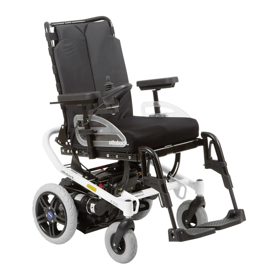
Batterien ggf. einsetzen und laden (siehe Kap. 6.5 / 6.5.1). Abb. 2 Hauptkomponenten Überprüfen Sie den festen Sitz des Batteriekabels im Stecker 1 Rückenlehne 5 Fußauflage (Abb. 3, Pos. 8) oder schieben Sie das Kabel ggf. in den Stecker ein. 2 Armauflage (Seitenteil) 6 J oystick 3 Joystick und Steuerung 7 Kippschutz (Abb. 3) 4 Sitzkissen 8 S tecker mit Batteriekabel (Abb. 3) Ottobock A200 |... -
Page 25: Transport Und Lagerung
Sichern Sie den Elektrorollstuhl beim Transport in einem WARNUNG anderen Fahrzeug ausreichend mit Spanngurten. Unfall- und Verletzungsgefahr durch unsachgemäße Zum Anbringen der Spanngurte befinden sich 4 Transportö- Anwendung als Transportsitz im Behindertentransport- sen am Rahmen des Elektrorollstuhls. Diese sind schon ab kraftwagen (BTW). Der Elektrorollstuhl ist unter Verwen- Werk vorhanden (siehe Abb. 4). dung der von Ottobock angebotenen Sicherungselemente (z. B. Beckengurt) und dem Einsatz geeigneter Rückhalte- systeme bedingt in Behindertentransportkraftwagen (BTW) einsetzbar. Es darf stets nur eine Person mit dem A200 befördert werden. Nutzen Sie während der Fahrt in einem BTW die im Fahrzeug installierten Sitze und dazu- gehörigen Rückhaltesysteme, um einen optimalen Schutz der Insassen bei einem Unfall zu erreichen. Nähere Informationen dazu enthält unsere Broschüre zur Nutzung der Ottobock Produkte in Behindertentransport- kraftwagen (BTW), Bestellnummer 646D158. Der Elektrorollstuhl darf grundsätzlich nur ohne Sitzkante- Abb. 4 Transportösen hinten, Transportösen vorn lung im BTW benutzt werden. Schalten Sie vor dem Transport des Elektrorollstuhls die Steuerung aus und verriegeln Sie die Bremse (siehe Kap. 6.4). -
Page 26: Notwendiges Zubehör
Beschädigung der Kabel. Achten Sie beim Zerlegen / Zusammenbau unbedingt darauf, dass keine Kabel ge- quetscht werden. Sie können das Packmaß des Elektrorollstuhls zum Trans- port durch einfache Handgriffe verringern. Legen Sie die entfernten Teile jeweils vorsichtig ab. Folgende Schritte sind beim Zerlegen der Reihenfolge nach einzuhalten: 1. Entfernen Sie das Bedienpult von der Armauflage (siehe Kap. 6.1.4). Abb. 5 Rückenlehne, umgeklappt 2. Entfernen Sie die Seitenteile (siehe Kap. 6.1.3). 3. Entfernen Sie die Fußrasten (siehe Kap. 6.1.5). Ottobock A200 |... -
Page 27: Abb. 6 Sitzverriegelung Lösen
Transport und Lagerung Abb. 7 Kippschutz, heruntergedrückt Abb. 6 Sitzverriegelung lösen 6. Entnehmen Sie die Akkupacks (Abb. 23). 7. Trennen des Rahmens vom Antriebsträger: Drücken Sie die Trittflächen oberhalb der Kippschutzrollen herunter, bis diese den Boden berühren (Abb. 7). 8. Jetzt kann der Rahmen durch leichtes Anheben und nach hinten ziehen vom Antriebsträger getrennt werden (Abb. 8). Abb. 8 Anheben des Rahmens Ottobock A200 |... -
Page 28: Abb. 9 Schnellspanner Lösen
Pfeile auf den Akkupacks in Fahrtrich- tung zeigen. Der Verriegelungshebel ist zur Sicherung der Akkupacks gegen Herausfallen wieder umzulegen (Abb. 10). Abb. 10 Sichern der Akkupacks Das Bedienpult kann auf den Akkupacks abgelegt oder in die vorgesehene Halterung gesteckt werden. Achten Sie darauf, dass das Bedienpult ausgeschaltet bleibt und keine Kabel gequetscht werden. Der Elektrorollstuhl ist nun fertig zerlegt (Abb. 11) und kann in ein Auto verpackt werden. HINWEIS Beschädigung durch ungenügende Arretierung. Sichern Sie die demontierten Teile des Elektrorollstuhls beim Trans- port ausreichend gegen Verrutschen. Abb. 9 Schnellspanner lösen Ottobock A200 |... -
Page 29: Abb. 11 A200 Demontiert
Transport und Lagerung nicht unvorhergesehen vom Antriebsträger lösen kann. (siehe Abb. 11b). Abb. 11 A200 demontiert Beim Zusammenbau des Elektrorollstuhls müssen Sie die oben angegebenen Schritte in umgekehrter Reihenfolge Abb. 11a Verriegelungsstange und Verriegelungsbolzen, eingerastet durchführen. Hierbei ist darauf zu achten, dass die Verriegelungsstange wieder richtig an ihre Position gedrückt wird (siehe Abb. 11a, Pos. 1) und beide Verriegelungsbolzen richtig einrasten (sie- he Abb. 11a, Pos. 2). VORSICHT Verletzungsgefahr durch nicht richtig eingerastete Ver- riegelung. Kontrollieren Sie das richtige Einrasten der Verriegelungs- bolzen an beiden Außenseiten des Grundträgers. Die Bol- Abb. 11b Verriegelungsbolzen, eingerastet zen müssen deutlich sichtbar sein, damit sich der Rahmen Ottobock A200... -
Page 30: Lagerung
Entnehmen Sie bei längeren Standzeiten oder beim Ver- sich unter Umständen permanente farbliche Veränderun- sand des Elektrorollstuhls die Siche r ung. gen an den Kontaktstellen zum Boden abzeichnen. Sorgen Sie deshalb bei längerer Standzeit für eine geeignete Un- terlage INFORMATION Eine schwarze Bereifung hinterlässt unter Umständen an den Kontaktflächen zum Boden schwarze Abriebstellen. Bei vorwiegender Benutzung in Innenräumen empfehlen wir Ihnen deshalb eine graue Bereifung. Ottobock A200 |... -
Page 31: Bedienung
Steht die Rückenlehne im gewünschten Winkel, rasten die rollstuhl die Befestigungsschrauben bzw. -muttern wieder Verriegelungen beim Loslassen des Verriegelungsgurtes in fest an. Beachten Sie dabei eventuell vorgegebene Dreh- die nächste Arretierung ein. momente. Am Elektrorollstuhl lassen sich verschiedene Einstellungen vornehmen. Sitzhöhe und Sitzposition sind gemäß der Kundenbestellung eingestellt und dürfen nur vom Fachhändler geändert wer- den. Vom Benutzer können angepasst werden: „ Rückenwinkel „ Sitzwinkel „ Armauflagenhöhe Abb. 12 Entriegelungsgurt Rückenlehne Ottobock A200 |... -
Page 32: Sitzwinkel
Der Elektrorollstuhl bietet eine 3-stufige Sitzwinkelverstellung gezogen wird. (0°, 3° und 6°). Die Einstellung erfolgt durch 2 Schnellspanner, welche sich vorn unterhalb des Sitzes befinden. Um den Sitzwinkel zu verstellen, werden die beiden Schnell- spanner gelöst (siehe Abb. 9). Durch gleichzeitiges, leichtes Anheben des Sitzes und nach hinten drücken der Laschen wird der gewünschte Sitzwinkel eingestellt. Es ist darauf zu achten, dass die Laschen in der jeweiligen Rastenposition ganz eingerastet sind. 6.1.3 Seitenteil mit Armauflage Abb. 13 Seitenteil herausnehmen Die Seitenteile lassen sich nach Lösen der Flügelschrauben nach oben herausnehmen (Abb. 13). Die Flügelschrauben befinden sich am unteren Ende der Armauflagenhalter (Abb.13, Pos. A). Ottobock A200 |... -
Page 33: Bedienpult
Beschädigung des Kabels führen. Die Schiene mit Bedienpult kann dann nach vorn bzw. nach Kabel nicht zu straff und nicht zu locker verlegen. Knicken hinten verschoben werden. Nach dieser Einstellung sind die und Quetschen des Kabels vermeiden. Schrauben wieder fest anzuziehen. Bedienpult entfernen Das Bedienpult kann durch einfaches Ziehen nach vorn ab- INFORMATION genommen werden. Ist die Bedienpultschiene zu lang, kann der überstehende Teil einfach abgesägt werden. Bei einem wegschwenkbaren Bedienpult (siehe Kap. 7.3) wird das Bedienpult vom Kugelkopf des Bedienpulthalters abgezogen (Abb. 14). Abb. 15 Anpassen des Bedienpults Abb. 14 Abziehen bei Bedienpulthalter wegschwenkbar Ottobock A200 |... -
Page 34: Fußraste
Es kann je nach Wunsch des Nutzers auch auf der anderen Seite des Elektrorollstuhls befestigt werden. 2. Hängen Sie das Wadenband an der Halterung ein. 6.1.5 Fußraste VORSICHT Quetschgefahr. Achten Sie darauf, dass Sie beim Aus- und Einklappen der Fußauflagen mit den Fingern nicht in den Gefahrenbereich gelangen. Die Fußrasten dürfen nur zum Transport des Rollstuhles vollständig aus ihrer Auf- nahme entnommen werden. Abbau Abb. 16 Arretierung der Fußraste 1. Hängen Sie das Wadenband aus. 2. Klappen Sie die Fußauflage hoch, lösen Sie die Arretie- rung der Fußraste (siehe Abb. 16) und schwenken Sie diese nach innen bzw. nach außen. Ottobock A200 |... -
Page 35: Ein- Und Aussteigen
Das Ein-/Aussteigen kann jeder Benutzer individuell in der für ihn am besten geeigneten Art und Weise vornehmen. 6.2.1 Von der Seite Zum seitlichen Einsteigen muss je nach Einstiegsseite das rechte bzw. linke Seitenteil demontiert werden. Fahren Sie Abb. 17 Einstellen Unterschenkellänge den Elektrorollstuhl so nah wie möglich an die Sitzfläche heran. Steigen Sie nach Möglichkeit immer auf der dem Bedien p ult gegenüber liegenden Seite ein. Ottobock A200 |... -
Page 36: Von Vorn
Nehmen Sie das Seitenteil – wie in Kap. 6.1.3 beschrieben – ab. Ggf. demontieren Sie die Fußraste (siehe Kap. 6.1.5). Der Benutzer kann jetzt von der Seite auf die Sitzfläche rut- schen. Das Verwenden eines Rutschbrettes erleichtert die- sen Vorgang. 6.2.2 Von vorn Abb. 18 Fußauflagen hochgeklappt Das Hochklappen der beiden Fußauflagen ermöglicht das Ein- und Aussteigen von vorn. Das seitliche Abschwenken der Fußrasten vergrößert den Ein- bzw. Ausstiegsbereich (Abb. 18/19). Mit Hilfe einer Begleitperson oder eines Transferlifters kann der Benutzer leicht in den Elektrorollstuhl ein- bzw. ausstei- gen. Hier bietet eine Drehscheibe Unterstützung. Abb. 19 Fußrasten seitlich abgeschwenkt Ottobock A200 |... -
Page 37: Steuerung
8 L adebuchse Unterseite Die Steuerung des Elektrorollstuhls erfolgt über das Bedien- (LED-Anzeige) pult. Das Bedienpult unterteilt sich in das Tastenfeld, das LED- Anzeigenfeld und den Joystick. An der Unterseite befindet sich die Lade-/Programmierbuchse. Der Elektrorollstuhl wird über das Bedienpult ein- und ausgeschaltet, Fahrbe- fehle können eingegeben und der aktuelle Status bestimm- ter Funktionen und Komponenten angezeigt werden. Ottobock A200 |... -
Page 38: Ein- Und Ausschalten
Wird die Steuerung eine Zeit lang nicht betätigt, LED-Anzeige „Ladezustand“ schaltet sich der Rollstuhl automatisch ab. Der Elektroroll- Die LEDs zeigen den Ladezustand der Batterie (siehe Kap. stuhl lässt sich auch während der Fahrt mit der Ein-/Aus- 6.3.4) Taste ausschalten. Er wird dann sofort abgebremst und kommt zum Stillstand. LED-Anzeige „Fahrstufen“ Die LEDs zeigen die momentan gewählte Fahrstufe. Ottobock A200 |... -
Page 39: Fahrfunktion
Fahrverhalten kommen. Daher ist die Ge- achten Sie beim Fahren mit dem Elektrorollstuhl folgende schwindigkeit stets der Beschaffenheit des Bodens anzu- Sicherheitsmaßnahmen: passen. „ Befahren von Steigungen und Gefällestrecken bis Zum Fahren wird der Joystick (siehe Abb. 20, Pos. 1) ver- max. 7° (12 %). wendet. Je weiter dieser von der Mittelstellung ausgelenkt „ Fahrgeschwindigkeit bei Bergabfahrt gemäß dem Ge- wird, desto schneller bewegt sich der Elektrorollstuhl in die- fälle reduzieren. se Richtung. „ Hindernisse mit einem Höhenunterschied > 15 mm nicht überqueren. Die jeweilige Maximalgeschwindigkeit bei vollem Ausschlag „ Stufen nicht ungebremst befahren. hängt von der gewählten Fahrstufe ab. Ottobock A200 |... -
Page 40: Led-Anzeige „Ladezustand
WARNUNG Unfall- und Verletzungsgefahr durch falsche Konfigura- INFORMATION tionseinstellungen. Geänderte Einstellungen von Para- Direkt nach dem Einschalten des Elektrorollstuhls zeigt die metern bei der Konfiguration führen zu einer Änderung des Batterieanzeige den gespeicherten Ladezustand nach Fahrverhaltens. Insbesondere Änderungen der Geschwin- dem letzten Betrieb. Der genaue Batteriestatus wird nach digkeits-, Beschleunigungs-, Brems- oder Joystickeinstel- kurzem Fahren angezeigt. lungen können zu unvorhergesehenen und in der Folge zu unkontrollierbaren Fahreigenschaften mit Unfallfolge führen. Erproben Sie nach Abschluss der Konfiguration/ Programmierung immer das Fahrverhalten des Elektroroll- stuhls. Ottobock A200 |... - Page 41 Bei vollständig geladener Batterie leuchten alle 10 LED- Batterieunterspannung Segmente. Mit dem fortlaufenden Erlöschen der LED-Seg- Blinklicht mente wird eine Ladungsminderung der Batterie angezeigt (siehe Tab. 2). Batterieüberspannung Blinken die letzten drei Segmente, muss die Batterie drin- Blinklicht gend geladen werden. Tab. 2 Batterieanzeige am Bedienpult Der Ladevorgang wird durch die Darstellung eines LED- Lauflichtes dargestellt. Während des Ladevorgangs ist die Fahrfunktion gesperrt. Ottobock A200 |...
-
Page 42: Reichweite
4. Joystick nach hinten auslenken bis zum Signalton. Folgende Faktoren beeinflussen die Reichweite eines Elektro- 5. Langer Signalton bestätigt die gesperrte Fahrfunktion; rollstuhls: die Steuerung schaltet sich ab. „ Kapazität der Batterien Die Aktivierung der Wegfahrsperre wird nach Einschalten „ Batteriealter der Steuerung durch ein Lauflicht in der LED-Anzeige „Fahr- „ Umgebungstemperatur stufen“ dargestellt (siehe Tab. 3). „ Fahrbelastung (z. B. durch Geländeprofil, Beschaffen- Anzeige Information heit des Untergrunds, Fahren mit Beleuchtung) Lauflicht LEDs „ Art und Weise des Ladevorgangs Wegfahrsperre Fahrstufenanzeige „ Nutzung elektrischer Optionen „ Körpergewicht des Benutzers Tab. 3 Anzeige der Wegfahrsperre am Bedienpult Ottobock A200 |... -
Page 43: Bremsentriegelung Und -Verriegelung
Die Wegfahrsperre ist deaktiviert und das Fahren wird frei- gegeben. WARNUNG Unfall- und Verletzungsgefahr durch fehlende Brems- INFORMATION funktion. „ Bei entriegelter Bremse (Schiebebetrieb) ist keinerlei Erfolgt die Joystickbewegung nicht korrekt, bleibt die Sper- Bremsfunktion vorhanden. re aktiv. Für eine erneute Deaktivierung der Wegfahrsperre muss die Steuerung ausgeschaltet werden. Der Elektro- „ Bei der Beförderung des Elektrorollstuhls auf einer rollstuhl kann erneut eingeschaltet und die Wegfahrsperre Strecke mit Neigung muss von der schiebenden Per- deaktiviert werden. son die entsprechende Bremskraft aufgebracht wer- den. „ Die Bremsfunktion darf nur in Anwesenheit einer Be- gleitperson entriegelt werden. „ Sollte der Benutzer die Bremsentriegelung nicht selbst erreichen können, kann die Bremse von der Begleit- person entriegelt werden. Ottobock A200 |... -
Page 44: Abb. 21 Bremsentriegelung
Batterie kann der Elektrorollstuhl geschoben werden. Dazu wird die Bremse über die mechanische Ent- riegelung gelöst. Die Bremsentriegelung befindet sich rechts und links an den Fahrmotoren. Bremse entriegeln Für den Schiebebetrieb werden die beiden links und rechts an den Fahrmotoren befindlichen roten Bremsentriegelungs- hebel nach außen gezogen. Die Steuerung erkennt in dieser Position die entriegelte Bremse und deaktiviert die Fahrfunk- Abb. 21 Bremsentriegelung tion. Die entriegelte Bremse wird durch Blinken der LED- Anzeige „Ladezustand“ angezeigt. Bremse verriegeln Zum Verriegeln der Bremse drücken Sie die roten Bremsen- INFORMATION triegelungshebel nach innen Zur Aktivierung der Fahrfunkti- Nach dem Umlegen des Bremsentriegelungshebels sind on müssen Sie die Steuerung aus- und wieder einschalten. sämtliche Bremssysteme ausgeschaltet. Ottobock A200 |... -
Page 45: Batterien
Arbeiten an den Batterien genau durch. Als zusätzliche Sicherheit und zur besseren Handhabung Beachten Sie die Entsorgungshinweise (siehe Kap. 11). sind die Batterien in separaten Akkupacks integriert. Durch spezielle Bleiplatten sind diese Batterien besonders geeig- Der Elektrorollstuhl wird werkseitig mit zwei wartungsfreien net für den Traktionsbetrieb und wurden auf hohe Zyklenfes- AGM-Batterien mit einer Gesamtkapazität von 28 Ah (C5) tigkeit ausgelegt. ausgestattet. Die Batterien befinden sich in 2 Akkupacks unter dem Sitz des Elektrorollstuhls (Abb. 22). Für Austausch bzw. Entsorgung der Batterien (Batterien im Akkupack) wenden Sie sich bitte an ihren autorisierten Zur Anzeige des Ladezustands der Batterie am Bedienpult Fachhändler. Die Batterien sind als komplette Einheiten (Ak- siehe Kapitel 6.3.4. kupacks) auszutauschen. Ottobock A200 |... -
Page 46: Abb. 23 Akkupack Entnehmen
Bedienung Zur Entnahme und zum Einbau der Akkupacks gehen Sie folgendermaßen vor: 1. Lösen Sie die Sitzverriegelung durch Ziehen des Entriegelungsgurtes und gleichzeitiges nach hinten klappen der Verriegelungsstange (Abb. 6). 2. Die Akkupacks liegen nun frei. Entnehmen Sie die Akkupacks (Abb. 23). 3. Stellen Sie die neuen Akkupacks wieder in den An- triebsträger. Achten Sie darauf, dass die roten Pfeile auf den Akkupacks in Fahrtrichtung zeigen und die Abb. 23 Akkupack entnehmen Steckkontakte (Abb. 24) in die Batteriekontakte eingrei- fen. 4. Der Verriegelungshebel ist zur Sicherung der Akkupacks gegen Herausfallen wieder umzulegen (Abb. 10). Abb. 24 Unterseite Akkupack Ottobock A200 |... -
Page 47: Laden
Batterien führt zur Tiefentladung der Batterie kann der Elektrorollstuhl bedenkenlos angeschlossen und schädigt sie. Der Elektrorollstuhl kann im entladenen bleiben, da das Ladegerät über eine programmierte Zustand stehen bleiben und den Benutzer in eine Gefah- Nachladephase verfügt, bei der die erreichte Kapazität ren-situation bringen. erhalten bleibt. Die Kapazität der Batterien bestimmt die Reichweite des „ Bei täglicher Benutzung empfiehlt es sich, das Ladege- Elektrorollstuhls. Viele Faktoren beeinflussen die Kapazität. rät über Nacht anzuschließen, um täglich über die volle Neben Temperatur, Batteriealter und Fahrbelastung wirkt Kapazität verfügen zu können. sich der Laderhythmus erheblich auf die Kapazität und so- „ Bei längeren Standzeiten kommt es zu einer allmähli- mit auf die Reichweite aus. chen Entladung der Batterien. Wird der Elektrorollstuhl Ottobock A200 |... -
Page 48: Ladegerät
„ Die Einstellung der Spannung am Ladegerät muss der länderspezifischen Spannung des jeweiligen Strom- HINWEIS netzes entsprechen. Beschädigung der Batterie. Eine falsch zugeordnete Ein- stellung kann die Batterie dauerhaft schädigen. 6.5.2 Ladegerät Beim Umgang mit dem Ladegerät sind folgende Sicher- WARNUNG heitsmaßnahmen einzuhalten: Explosionsgefahr durch Funkenbildung. Vor dem Ab- „ Das Ladegerät immer mit den Gummifüßen auf ebenen trennen der Batterie muss das Ladegerät grundsätzlich Untergrund stellen. abgeschaltet und der Netzstecker gezogen werden. Ottobock A200 |... -
Page 49: Zubehör
Unfallgefahr durch nicht gesicherte Verschraubungen. Stecker des Ladegeräts am Bedienpult ziehen. Ersetzen Sie nach dem Lösen von Verschraubungen mit 5. Steuerung einschalten, der Elektrorollstuhl ist fahrbereit. Gewindesicherung diese durch neue oder sichern Sie die- se ggf. mit Gewindesicherungsmasse mittlerer Festigkeit Weitere Details zur Bedienung und zu den LED-Anzeigen (z. B. EuroLock A24.20). siehe die mitgelieferte Gebrauchsanweisung des Ladege- räts. Ottobock A200 |... -
Page 50: Mechanische Rückenwinkelverstellung
Öl an der Kolbenstange geachtet werden. Le- ckagen mindern die Funktionsfähigkeit der Gasdruckfe- 2. Rückenlehne in gewünschte Stellung bewegen. dern bzw. führen zu deren Ausfall. 3. Auslösehebel loslassen (Gasdruckfeder wieder blockiert). Defekte Gasdruckfedern (z. B. durch Kratzer oder Schä- den an der Kolbenstange infolge Schlageinwirkung; Defor- mation des Zylinderrohres) sind umgehend auszutauschen. Kolbenstangen werden nicht gefettet. Sie sind wartungs- frei. Ottobock A200 |... -
Page 51: Besonderheiten Zur Transportvorbereitung
Abb. 25 Mechanische Rückenwinkelverstellung 7.1.1 Besonderheiten zur Transportvorbereitung VORSICHT Unfall- und Verletzungsgefahr durch falsch montierte Rückenlehne. Achten Sie darauf, dass die Verriegelung am Querbolzen einrastet (Abb. 26). Prüfen Sie den Quer- Abb. 26 Querbolzen in Halterung verriegelt bolzen und die Verriegelung auf festen Sitz. 1 Querbolzen 2 Verriegelung mit Hebel Für die Verringerung des Packmaßes (zum Beispiel beim Zerlegen des Elektrorollstuhls) ist Folgendes an der mecha- nischen Rückenwinkelverstellung vorzunehmen: Ottobock A200 |... -
Page 52: Mechanisch Hochschwenkbare Fußraste
Querbolzen ein. Abb. 27 Mechanisch hochschwenkbare Fußraste 7.2 Mechanisch hochschwenkbare Fußraste Der Elektrorollstuhl kann mit mechanisch hochschwenkbaren 7.3 Wegschwenkbarer Bedienpulthalter Fußrasten ausgerüstet werden (siehe Abb. 27). Um mit dem Elektrorollstuhl unter eine Tischkante oder nä- Um die Fußraste nach oben zu schwenken: her an ein Objekt heranzufahren, kann mit einem speziellen Halter das Bedienpult seitlich weggeschwenkt werden 1. Auslösehebel an der Fußraste betätigen (Blockierung (siehe Abb. 28). der Gasdruckfeder wird aufgehoben, siehe Abb. 27, Pfeil). 1. Bedienpulthalter mit etwas Druck zur Seite drücken, das Drehelement wird entriegelt. 2. Fußraste in gewünschte Stellung bewegen. 2. Bedienpulthalter seitlich wegschwenken. 3. Auslösehebel loslassen (Gasdruckfeder wird wieder blockiert). 3. Beim Zurückdrehen in die Ursprungsposition rastet das Drehelement wieder ein. Ottobock A200 |... -
Page 53: Beckengurt
Der Beckengurt darf keinesfalls als Teil eines Zum Anlegen des Beckengurtes werden beide Verschluss- Rückhaltesystems beim Transport im BTW verwendet hälften bis zum Einrasten ineinander gesteckt (Abb. 29). werden. Das Gurtschloss muss hörbar einrasten. Anschließend ist eine Zugprobe durchzuführen. Der Beckengurt wird durch Drücken der roten Entriege- lungstaste geöffnet. Ottobock A200 |... -
Page 54: Weitere Optionen
Schnalle kann die Position der Verschlusshälften 80 mm. variiert werden. Die überschüssige Gurtlänge wird durch „ Pannensichere Bereifung: Vollgummireifen die Kunststoffschieber aufgefangen. „ Contour-Sitze klein/groß: für besseren Sitzkomfort und mehr Anpassmöglichkeiten „ Standardsitz Junior „ Armlagerungszubehör: Spezialadapter für die Armlagen aus unserem Zubehörkatalog „ Adapter für Montageset Kopfstützenbefestigung: Zum Anbau am Rückenrohr „ Zusatzbeleuchtung Diese und weitere optionale Anbauteile sind im Bestellblatt und im Zubehörkatalog enthalten. Abb. 29 Beckengurt anlegen Ottobock A200 |... -
Page 55: Störung/Störungsbeseitigung
Systemanalyse durchzuführen. vorhanden, kann durch Entriegelung der Bremse (siehe Kap. 6.4) in die Schiebefunktion umgeschaltet werden. Alle aufgetretenen Störungen werden in einer Liste gespei- Suchen Sie nach einem Not-Stopp dringend einen Fach- chert und können z. B. bei einer Generalüberholung des händler auf! Elektrorollstuhls abgerufen werden. Aus den gespeicherten Daten können z. B. weitere Service- und Wartungsintervalle abgeleitet werden. Ottobock A200 |... - Page 56 Störung/Störungsbeseitigung VORSICHT Unfallgefahr durch unkontrolliertes Fahrverhalten. Beim Betrieb des Elektrorollstuhls kann es aufgrund von Störun- gen zu unkontrollierten Bewegungen kommen. Wenden Sie sich in diesem Fall unverzüglich an ihren autorisierten Fachhändler. HINWEIS Fehlfunktion an der Steuerung. Die Steuerung gibt bei entriegelter Bremse und Betätigen des Joysticks ein Feh- lersignal auf dem Bedienpult aus. Ist das nicht der Fall, liegt eine Fehlfunktion vor, die umgehend von einem Fach- händler behoben werden muss. Ein Fehler beeinträchtigt eine oder mehrere Funktionen des Elektrorollstuhls. Bis der Fehler behoben wird, ist das Sys- tem nicht voll lauffähig. Ottobock A200 |...
- Page 57 Fehlerhafte Verkabelung z. B. fehlerhafte Stecker- Verbindungen zum des linken Motors verbindung linken Motor prüfen Defekter Motor Motor prüfen Kurzschluss an der z. B. Kabelbruch Verbindung der Batterie zum Batterieverbindung zum linken Motor prüfen linken Motor Fehlerhafte Verkabelung z. B. fehlerhafte Stecker- Verbindungen zum des rechten Motors verbindung rechten Motor prüfen Defekter Motor Motor prüfen Kurzschluss an der z. B. Kabelbruch Verbindung der Batterie zum Batterieverbindung rechten Motor prüfen zum rechten Motor Fahrfunktion gesperrt evtl. Ladegerät angeschlossen Ladegerät entfernen aufgrund äußerer Einflüsse Joystickfehler Joystick nicht in Nullposition Joystick vor Einschalten beim Einschalten in Nullposition bringen Ottobock A200 |...
- Page 58 Störung/Störungsbeseitigung Blinkende LED Fehler/Warnung Ursache Mögliche Maßnahme Controllerfehler Controller defekt Alle Verbindungen prüfen Bremsentriegelung Bremsentriegelung offen Überprüfen der Motorbremsen/ Überprüfen der Verbindungen zum Controller Batterieüberspannung Spannung zu hoch Langsam weiterfahren Batteriekontakte locker Steckerkontakte überprüfen Kommunikationsfehler Defektes Kabel, lose Stecker- Verbindungen prüfen zwischen Bedienpult verbindung (Joystick) und Controller Tab. 5 Status- und Fehlermeldungen Ottobock A200 |...
-
Page 59: Wartung Und Pflege
Wartung und Pflege Wartung und Pflege INFORMATION Für die Bestellung von Ersatzteilen kann bei Ottobock ein Ersatzteilkatalog angefordert werden. Es dürfen nur Er- satzteile von Ottobock verwendet werden. Nichtbeachten führt zum Verlust von Gewährleistungsansprüchen. INFORMATION Treten bei der Wartung Probleme auf, muss ein autorisier- ter Fachhändler konsultiert werden. Der Elektrorollstuhl ist einmal jährlich beim autorisierten Fachhändler auf Fahr- sicherheit prüfen zu lassen. 9.1 Wartungsintervalle Vor jedem Einsatz ist die Funktionsfähigkeit des Elektroroll- stuhls zu prüfen. Die in Tabelle 7 beschriebenen Tätigkeiten sind in den angegebenen Intervallen vom Benutzer durchzu- führen. Ottobock A200 |... - Page 60 Wartung und Pflege vor jeder Komponente Tätigkeit wöchentlich monatlich Fahrt Armauflage und Befestigungsschrauben angezogen Seitenteil Armauflage und Bedienteil gesichert Armauflage auf Beschädigungen überprüfen Antriebsräder Räder müssen frei und ohne Seitenschlag drehen Zentralmutter auf der Antriebswelle angezogen Radbefestigung auf festen Sitz prüfen Geradeauslauf gesamter Rollstuhl Bereifung Luftdruck (siehe Reifenmantel) Ausreichende Profiltiefe, mindestens 1 mm Auf Beschädigung prüfen Batterien Ladezustand der Batterie prüfen Elektronik Steuerung ohne Fehlermeldung Ladegerät zeigt keine Fehlermeldung an den LEDs Steckverbindungen prüfen Bremse Bremshebel bei eingeschalteter Steuerung betätigen Bremsfunktion bei eingeriegelter Bremse aktiv Ottobock A200 |...
- Page 61 Wartung und Pflege vor jeder Komponente Tätigkeit wöchentlich monatlich Fahrt Fußraste Rastung auf Funktion und festen Sitz prüfen mechanisch Fußauflagen auf Beschädigungen überprüfen hochschwenkbar Sichtprüfung auf Kratzer an der Kolbenstange und Ölverlust Lenk-/ Spielfreier Sitz der Gabel in der Aufnahme Schwenkräder Räder müssen frei und ohne Seitenschlag drehen Befestigungsmutter angezogen Polsterung und Einwandfreier Zustand der Polsterung Gurte Keine Abnutzung an den Befestigungsgurten Gurtschloss auf Funktion überprüfen Sitzbefestigung Befestigungsschrauben auf festen Sitz prüfen Gasdruckfeder Sichtprüfung auf Kratzer an der Kolbenstange und (Option) oder Ölverlust Aktuator Tab. 6 Wartungsmaßnahmen und -intervalle Ottobock A200 |...
-
Page 62: Sicherung Wechseln
Unnötiges Abstellen im Freien sollte vermieden werden. schen den Kontakten an der Unterseite der Batterien Unabhängig vom Verschleiß sollte die Bereifung im Ab- ein. Achten Sie darauf, dass die Sicherung mittig in die stand von 2 Jahren ausgetauscht werden. dafür vorgesehenen Federkontakte eingedrückt wird Bei längeren Standzeiten oder starker Erwärmung der Rei- und nicht seitlich schräg anliegt. fen (z. B. in der Nähe von Heizkörpern oder bei Sonnenein- strahlung durch Glasscheiben) kommt es zu einer bleiben- 4. Setzen Sie die Batterien wieder ein (siehe Kap. 6.5). den Verformung der Reifen. Achten Sie deshalb stets auf genügend Abstand zu Wärmequellen, bewegen Sie Ihren Stuhl des Öfteren oder schaffen Sie sich bei Einlagerung die Möglichkeit des Aufbockens. Gehen Sie beim Reifen-/Schlauchwechsel an einem An- triebsrad folgendermaßen vor: 1. Sichern Sie den Rollstuhl gegen seitliches Abkippen durch eine geeignete Unterlage unter dem Antriebsträger. Abb. 30 Akkupack mit Sicherung Ottobock A200 |... -
Page 63: Abb. 31 Demontage Antriebsrad
Wartung und Pflege 2. Zur Demontage eines Antriebsrades die 4 Innensechs- Beim Radwechsel an einem Vorderrad gehen Sie folgender- kantschrauben mit Innensechskantschlüssel Größe 8 maßen vor: in der Mitte des Rades lösen (Abb. 31) und das Rad 1. Achsschraube zum Ausbau des Vorderrades mit abnehmen. Innensechskantschlüssel Größe 6 lösen 3. Um bei Antriebsrädern den Reifen/Schlauch zu (siehe Abb. 32, Pos. 1) und die Achse herausziehen. wechseln, an der Innenseite der Felge die Schrauben 2. Das defekte Rad ist jetzt frei zugänglich und kann mit Innensechskantschlüssel Größe 8 lösen und die gewechselt werden. zweigeteilte Felge auseinanderziehen. 4. Der defekte Schlauch ist jetzt frei zugänglich und kann gewechselt werden. Abb. 32 Demontage Vorderrad 1 Achsschraube Abb. 31 Demontage Antriebsrad Ottobock A200 |... -
Page 64: Reinigung Und Pflege
Lösungsmittel oder harte Bürsten verwen- nen Anwendungshinweise zu beachten. den. Die Reinigung auf keinen Fall mit Wasserstrahl oder „ Vor einer Desinfektion sind die Sitz- und Rückenbespan- Hochdruckreiniger durchführen. nung, die Sitzkissen, das Bedienpult und die Armaufla- ge zu reinigen. INFORMATION Vor einer Desinfektion sind Sitz- und Rückenbespannung, Sitzkissen sowie Bedienpult und Armauflage zu reinigen. Der Elektrorollstuhl muss in regelmäßigen Abständen, ab- hängig vom Einsatz- und Verschmutzungsgrad, gereinigt werden. Die Komponenten Bedienpult, Ladegerät, Armauflage und Verkleidung können mit einem feuchten Tuch und einer mil- den Reinigungslösung gesäubert werden. Ottobock A200 |... -
Page 65: Entsorgung
INFORMATION 5 Jahre kalkuliert. Zeiten der Einlagerung beim Fachhändler Im Entsorgungsfall sind alle Komponenten und Materialien oder Kostenträger gehören nicht dazu. Dabei ist deutlich des Elektrorollstuhls umwelt- und sortengerecht zu entsor- hervorzuheben, dass das Produkt bei entsprechender Pfle- gen oder einer Wiederaufbereitung zuzuführen. ge und Wartung weit über diesen definierten Zeitraum hin- aus zuverlässig ist. Wird der Elektrorollstuhl nicht mehr genutzt, muss er gemäß den jeweiligen landesspezifisch geltenden Umweltschutz- Für den Wiedereinsatz ist das betreffende Produkt zunächst bestimmungen entsorgt werden. gründlich zu reinigen und zu desinfizieren. Defekte Batterien (im Akkupack) werden beim Erwerb neuer Anschließend ist das Produkt von einem autorisierten Fach- Batterien beim Fachhändler im Tausch zurückgenommen. mann auf Zustand, Verschleiß und Beschädigungen zu überprüfen. Ottobock A200 |... -
Page 66: Rechtliche Hinweise
11 Rechtliche Hinweise neuen Anwender unpassende/ungeeignete Komponenten 11.1 Nutzungsdauer sind auszutauschen. Aufgrund der Marktbeobachtung und dem Stand der Tech- Ein Serviceplan für jedes Modell, Detailinformationen sowie nik hat der Hersteller den Einsatz des Produktes unter Ein- die benötigten Werkzeuge sind der Service-Anleitung zu ent- haltung des bestimmungsgemäßen Gebrauchs und unter nehmen. Einbeziehung der Service- und Wartungsvorgaben auf 5 Jahre kalkuliert. Zeiten der Einlagerung beim Fachhändler oder Kostenträger gehören nicht dazu. Dabei ist deutlich hervorzuheben, dass das Produkt bei ent- sprechender Pflege und Wartung weit über diesen definier- ten Zeitraum hinaus zuverlässig ist. Wird die Nutzungsdauer erreicht, sollte sich der Benutzer oder eine verantwortliche Hilfsperson an das Fachpersonal wenden, das das Produkt angepasst hat oder an den Ser- vice des Herstellers (Adresse siehe hintere Umschlaginnen- seite oder Rückseite). Ottobock A200 |... -
Page 67: Haftung
Richtlinie 93/42/EWG für Medizinprodukte. Aufgrund der den Rechten der jeweiligen Eigentümer. Klassifizierungskriterien nach Anhang IX dieser Richtlinie Aus dem Fehlen einer expliziten Kennzeichnung, der in die- wurde das Produkt in die Klasse I eingestuft. Die Konformi- sem Begleitdokument verwendeten Marken, kann nicht ge- tätserklärung wurde deshalb vom Hersteller in alleiniger schlossen werden, dass eine Bezeichnung frei von Rechten Verantwortung gemäß Anhang VII der Richtlinie erstellt. Dritter ist. Das Produkt erfüllt die Anforderungen der RoHS-Richtlinie 2011/65/EU des Europäischen Parlaments und des Rates vom 08.06.2011 zur Beschränkung der Verwendung gefähr- licher Stoffe in Elektro- und Elektronikkomponenten und Ge- räten. Ottobock A200 |... -
Page 68: Technische Daten
Technische Daten 12 Technische Daten Allgemeine Information Anwendungsklasse (gemäß DIN EN 12184) Klasse A Maße und Gewichte Sitzbreite Standardsitz: 340 – 480 mm Contour-Sitz: 380 – 480 mm Sitztiefe Standardsitz: 340 – 500 mm Contour-Sitz: 360 – 480 mm Sitzhöhe Standardsitz: 430 / 480 mm Contour-Sitz: 510 / 560 mm Armauflagenhöhe 225 – 350 mm Standardsitz Junior: 205 – 275 mm Armauflagenlänge 260 mm Unterschenkellänge Standardsitz: 250 – 470 mm Contour-Sitz: 280 – 540 mm Rückenhöhe 550 / 500 / 450 mm Rückenwinkel manuell, in 10°-Schritten: -9°/1°/11°/21° oder 0°/10°/20°/30° Rückenwinkelverstellung mechanisch: um bis zu 30° verstellbar Ottobock A200 |... - Page 69 Technische Daten Maße und Gewichte Gesamtbreite 570 mm Gesamthöhe 1030 mm Gesamtlänge 1000 mm Wendebereich* 1290 mm Radius Wendekreis 870 mm Reifengröße Lenkrad 8" Antriebsrad 12.1/2x2.1/4" Luftdruck siehe Reifenmantel Leergewicht** 66 kg (abhängig von Optionen) Transportgewichte** siehe Leergewicht**, davon: Seitenteil: < 1 kg Fußraste (Grundausstattung): ca. 1 kg Fußraste mechanisch hochschwenkbar: 1,8 kg Batterie entnehmbar: ca. 11 kg (pro Stück) max. Zuladung 100 kg (Patientengewicht); Standardsitz Junior: 75 kg Ottobock A200 |...
- Page 70 Elektrische Anlage*** IP-Schutzart (gemäß DIN 60529) IPX4 Betriebsspannung 24 V Batterien (AGM-Batterien): 2 x 12 V, 28 Ah (CS) Steuerung: Modell VR2 mit Controller und Bedienpult Betriebsspannung 24 V DC Max. Ausgangsstrom pro Motor 60 A Schmelzssicherung je 60 A im Batteriepack Ladegerät Details siehe mitgelieferte Gebrauchsanweisung des Ladegeräts Fahrdaten Geschwindigkeit 6 km/h [3,7 mph] Maximal sichere Neigung Steigfähigkeit****: 7° (12 %) überwindbare Hindernisse 15 mm Reichweite (in der Ebene)***** ca. 15 km Bremsweg bei 6,0 km [3,7 mph]: 1 000 mm (auf der Waagrechten) / (gemäß DIN EN 12184:2009)****** 2000 mm (auf der Neigung) Betriebstemperatur -15 °C bis +40 °C Transport- und Lagertemperatur -15 °C bis +40 °C Ottobock A200 |...
- Page 71 Technische Daten Schutz gegen Korrosion Korrosionsschutz: Pulverbeschichteter Rahmen * Wenden in 3 Zügen um 180° ** Die Gewichtsangaben variieren gemäß Options- und Variantenauswahl. *** Das Produkt erfüllt alle Anforderungen der ISO 7176-14. **** Die Dauersteigfähigkeit kann individuell erheblich niedriger sein als die angegebene Steigfähigkeit. ***** D ie angegebene Reichweite wurde unter definierten Bedingungen gemäß ISO 7176-4 ermittelt. In der Praxis kann sich die Reichweite um bis zu 50 % reduzieren. Siehe dazu das Kapitel „Reichweite“ in der Gebrauchsanweisung (Benutzer). ****** D er Bremsweg kann sich aufgrund von Nutzergewicht, angebauten Optionen und Reifenzustand sowie von Witterungsverhältnissen und Unter- grund entsprechend verlängern. Technische Änderungen vorbehalten. Tab. 7 Technische Daten Ottobock A200 |...
- Page 72 Instructions for Use Instructions for Use Ottobock A200 |...
- Page 73 6.1.4 Control panel ............. 102 2.6 Safety Requirements for Care, 6.1.5 Footrest .............. 103 Maintenance and Disposal ........86 6.2 Getting Into and Out of the Power Wheelchair ... 104 2.7 Requirements for the User ........88 6.2.1 From the side ............. 104 2.8 Safety Functions........... 88 6.2.2 From the front ............. 105 2.9 Warning Symbols and Type Plates ....... 89 6.3 Control Unit ............105 Product Description ..........92 Ottobock A200 |...
- Page 74 11.3 CE Conformity ........... 135 7.1.1 Specialties for preparing power wheelchair for transport ............119 11.4 Warranty terms ..........135 7.2 Mechanically Elevating Footrest ......120 11.5 Trademarks ............135 7.3 Swing-away Control Panel Holder ...... 121 Technical Data ..........136 7.4 Lap Belt ............. 121 7.5 Other Options ............ 122 Malfunctions / Troubleshooting ......123 8.1 Warning ............. 123 8.2 Errors ..............123 Ottobock A200 |...
- Page 75 Fig. 9 Loosening the quick clamp ......97 Fig. 28 Swing-away control panel holder ....121 Fig. 10 Securing the battery packs ......97 Fig. 29 Applying the lap belt ........122 Fig. 11 A200 disassembled ......... 98 Fig. 30 Battery pack with fuse ........130 Fig. 11a Locking bar and locking pins, engaged ... 98 Fig. 31 Disassembling drive wheel ......131 Fig. 11b Locking pin, engaged ........98 Fig. 32 Disassembling front wheel ......131 Fig. 12 Release strap for the backrest ......
-
Page 76: General Information
General Information General Information 1.1 Preface These instructions for use provide the user as well as his or her attendants with all the required knowledge on the de- INFORMATION sign, function, operation and maintenance of the A200 pow- Date of the last update: 2014-06-06 er wheelchair from Otto Bock Mobility Solutions GmbH. The „ Please read this document carefully. instructions contain all the information that is needed to use „ Follow the safety instructions. the power wheelchair safely, to determine the possible caus- es of a malfunction and to help eliminate it. INFORMATION Knowledge of these instructions for use is absolutely neces- You can request this document as a PDF file from the sary for ensuring that the power wheelchair is used safely. Customer Care Center (CCC) at oa@ottobock.com Therefore, the user and his or her attendants must read the or from the manufacturer’s service department (see instructions for use thoroughly, especially the section on inside back cover or back page for addresses). -
Page 77: Field Of Application
Training users and attendants to use the power are able to move independently in such a power wheelchair. wheelchair is required for protecting persons from danger and for ensuring that the power wheelchair is operated Fitting considerations: safely and correctly. „ Body size and body weight (max. load capacity 100 kg; The operational safety of the power wheelchair can only be standard seat Junior: 75 kg) ensured if it is used properly in accordance with the informa- „ Physical and psychological limitations tion contained in these instructions for use. The user is ulti- „ Age of the patient mately responsible for accident-free operation. „ Home conditions „ Environment Ottobock A200 |... -
Page 78: Service
Safety Safety 1.4 Service INFORMATION 2.1 Explanation of Symbols Service and repairs on the power wheelchair are always carried out by experts at specialist dealers who have been WARNING authorised and trained by Ottobock. Should any problems Warnings regarding possible risks of severe accident or in- arise, please contact your power wheelchair supplier. jury. Should you have any questions or a problem that cannot be resolved despite using the instructions for use, please con- CAUTION tact Ottobock Service (see back side of cover for address). Warnings regarding possible risks of accident or injury. Ottobock endeavours to support their customers in all re- NOTICE spects in order to keep them satisfied with their product for a long time. Warnings regarding possible technical damage. INFORMATION Information regarding operation. Information for service per- sonnel. Ottobock A200 |... -
Page 79: Standards And Directives
The power wheelchair has been constructed in accordance with the currently valid technical rules and is safe to oper- CAUTION ate. The safety of the power wheelchair is confirmed by the Risk of accident and injury due to improper use. The CE symbol and the declaration of conformity. may only be used properly. The may only be used by per- sons trained to use it. CAUTION Risk of burns when near to fire. The back upholstery and seat cushion of the power wheelchair are not highly flam- mable, but can however catch fire. Therefore utmost cau- tion near any sources of open flame or sparks, especially lit cigarettes, is required. Ottobock A200 |... -
Page 80: Safety Requirements For Transportation, Storage And Assembly
Only use original manufacturer’s options. The optional offered by Ottobock. The power wheelchair may be used components may be mounted only as described here. Fail- for transporting only one person. We recommend that ure to comply will void the warranty. wherever and whenever possible, power wheelchair users transfer in the seats installed in the motor vehicle and use the corresponding vehicle restraint system, because this is the only way to ensure optimal protection of the passen- gers in case of an accident. For more information, please refer to our brochure on us- ing Ottobock products in wheelchairaccessible vehicles, order number 646D158. The power wheelchair may generally be used in motor ve- hicles for the disabled without seat tilt. Ottobock A200 |... - Page 81 For more information please visit the www.iata.org web- site. Ottobock recommends contacting the airline directly INFORMATION before every flight to obtain information regarding special The tyres of the power wheelchair contain chemical sub- transport regulations. stances that can react to other chemical substances (such as cleaning agents, acids). WARNING For this reason, place a suitable mat underneath the Risk of damage as a result of improper transportation. wheelchair, if it is not going to be used over an extended For transportation of the power wheelchair, only use hoist- period of time. ing devices with a sufficient capacity. The A200 must be secured in accordance with the regulations for the trans- portation device used. Only attach the tensioning straps to the corresponding attachment eyes. Ottobock A200 |...
-
Page 82: Safety Requirements For Operation
To ensure safe driving operation, the anti-tipper ration can lead to changes in driving characteristics. In must have been mounted correctly and must be in proper particular, changes to the speed, acceleration, braking or condition. joystick settings can lead to unexpected and therefore un- controllable operating performance with a risk of acci- INFORMATION dents. Always test the driving characteristics of the power Prior to using the power wheelchair, all the necessary me- wheelchair after configuration / programming is complete. Programming must only be completed by authorised per- chanical adaptations (e. g. mounting special controls) and software settings (e. g. programming the control) must be sonnel. Neither Ottobock nor the control unit manufacturer are liable for damages caused by programming that was made to comply with the individual requirements and abili- not properly / professionally adapted to the abilities of the ties of the user. The settings may only be made by trained specialists who have been authorised by Ottobock. wheelchair user. Ottobock A200 |... - Page 83 Risk of tipping over when driving on inadequate sur- WARNING face. Using the power wheelchair on very slippery ground Risk of injury if the power wheelchair tips over during (such as icy surfaces) or on very coarse-grained surfaces driving. The has been approved for driving on inclines and (gravel or pebbles) is not permitted. slopes of no more than 7° (12 %). Navigating inclines above this percentage value is not permitted. WARNING The critical obstacle height of the A200 is 15 mm. It is not Risk of tipping when using lifting platforms. During permitted to cross obstacles higher than 15 mm. transport on lifting platforms or in lifts, the wheelchair con- Operating the power wheelchair on stairs is not permitted. trols must be switched off. Lock the brake. WARNING WARNING Risk of accident if the power wheelchair tips over during Risk of tipping due to centre of gravity shifting. Getting driving. Reduce the driving speed when driving downhill (e.g.
- Page 84 Risk of accident due to uncontrolled driving behaviour. CAUTION Uncontrolled movements can occur during the operation of the power wheelchair as a result of malfunction. In this Risk of accident as a result of wearing improper cloth- case, please contact your authorised dealer immediately. If ing. When driving in the dark, Ottobock strongly recom- any faults, defects or other dangers that can lead to per- mends that the user wears bright clothes or clothing with sonal injury are detected, the power wheelchair must be reflectors. put out of operation immediately. Ottobock A200 |...
- Page 85 Take care of the following particularities during heat, move your wheelchair from time to time, or jack up the operation: the wheelchair when storing it. The driving characteristics of the power wheelchair can be affected by electromagnetic fields (mobile phones or other NOTICE radiating devices). Please switch off all mobile devices Risk of tyre damage. Too high an air pressure in your when driving. tyres may result in tyre defect. Please observe the data in The power wheelchair can generate electromagnetic fields Section “Technical Data“. The maximum air pressure must that can cause interference with other devices. Therefore, not be exceeded. switch off the controls whenever you do not need them. Ottobock A200 |...
-
Page 86: Safety Requirements For Care, Maintenance And Disposal
Ottobock may do maintenance INFORMATION work on the power wheelchair. This also applies to all re- After each emergency stop, the controls of the power pairs and settings on the brakes. Incorrect settings can wheelchair must be turned on again. In the event of com- lead to brake failure. munication problems in the bus system of the controls, the system triggers an emergency stop and thus prevents any uncontrolled functions. If the driving function is still not available after switching the controls on again, unlock the brakes to activate the push mode. In this case, contact a specialist dealer as soon as possible. Ottobock A200 |... - Page 87 CAUTION INFORMATION Defective batteries must be disposed of properly in ac- Risk of injury due to uncontrolled movements. The fuse must always be removed for any maintenance work where cordance with country-specific regulations. the battery cover is open. NOTICE Unauthorized battery replacement. The battery may only be replaced by a specialist dealer. The characteristic curve of the battery charger set at the factory corresponds to the battery provided and must not be changed. Setting the characteristic curve incorrectly can result in permanent damage to the battery. Ottobock A200 |...
-
Page 88: Requirements For The User
O ttobock. If any malfunctions occur such as an insufficient supply of energy to the brake, the software will recognize them and The operator must have read and understood all the infor- trigger the emergency stop brake or reduce the speed of mation in the instructions for use. the power wheelchair. At the same time, a warning signal The wheelchair may not be operated in cases of exhaus- will be emitted. tion or under the influence of alcohol or medications. The operator must not have any mental limitations which can temporarily or permanently restrict attentiveness and judgment. Ottobock A200 |... -
Page 89: Warning Symbols And Type Plates
Safety 2.9 Warning Symbols and Type Plates Fig. 1 Signage on the A200 Ottobock A200 |... - Page 90 Safety Label/Type Plate Explanation A Type designation B European article number (EAN) C Maximum load capacity (see Section „Technical Data“) D Maximum climbing ability (see Section „Technical Data“) E Maximum speed (see Section „Technical Data“) F Symbol for separate collection of electric and electronic devices. Components of the power wheelchair and the batteries must not be disposed of like regular domestic waste. G CE marking – product safety in conformity with EC Directives H Serial number I Read the Instructions for Use prior to using the product. Observe the safety instructions in the Instructions for Use. J Manufacturer / address The type plate is located on the side of the K Product reference number frame below the seat. Close the lock bar prior to use. Observe the safety instructions in the In- structions for Use manual. CLOSE Ottobock A200 |...
- Page 91 Safety Label/Type Plate Explanation Components of the power wheelchair and the batteries must not be dis- posed of like regular domestic waste. Table 1 Signage on the A200 Ottobock A200 |...
-
Page 92: Product Description
„ Charger adjusted. „ Instructions for Use The special features of the power wheelchair include: „ Options (see section 7) „ Compact design. Upon delivery by the specialist dealer the power wheelchair „ Easy to disassemble for transport. is ready for use. All the settings correspond to the indica- tions on the order form or are adjusted directly on site by the „ Easy to service due to modular component group concept. dealer. The power wheelchair is adapted to the personal re- „ Easy access to all component groups. quirements of the individual. The functions of the individual components can be tested by following the instructions in section 6. Possible malfunctions are described in section 8. Ottobock A200 |... -
Page 93: Initial Operation
4.2 Initial Operation WARNING Risk of suffocation. Packaging materials must be kept out of reach of children. Prior to putting the power wheelchair into operation, the com- Fig. 2 Main components pleteness (see fig. 2) and function of all its components must be checked. Insert and charge batteries if need be (see sec- 1 Backrest 5 Footrest tion 6.5 / 6.5.1). 2 Armrest (side panel) 6 J oystick Check the firm seat of the battery cable in connector (Fig. 3, 3 Joystick and control unit 7 Anti-tipper (Fig. 3) item 8) or insert the cable into the connector. 4 Seat cushion 8 Connector with battery cable (Fig. 3) Ottobock A200 |... -
Page 94: Transportation And Storage
(such as lap belt) as well as appropriate restraint systems offered by Ottobock. The A200 may be used for transport- ing only one person. We recommend that wherever and whenever possible, A200 users transfer in the seats in- stalled in the motor vehicle and use the corresponding ve- hicle restraint system, because this is the only way to en- sure optimal protection of the passengers in case of an accident. -
Page 95: Required Accessories
(491S00=SK028 Anchor Point Kit). INFORMATION To proceed when using the option of “Mechanical back an- The qualified personnel which fit the wheelchair can provide gle adjustment” see section 7.1.1. more information. 5. Release the seat lock by simultaneously pulling the release strap and folding the locking bar to the rear 5.2 Disassembling the Power Wheelchair (Fig. 6). The battery packs are free. NOTICE Risk of cable damage. Make sure that no cables are pinched during disassembly / reassembly. You can reduce the folding size of the power wheelchair for transportation by easy dismantling. Carefully lay down the removed components. Please observe the following order for disassembly: 1. Remove the control panel from the armrest (see section 6.1.4). Fig. 5 Backrest folded down 2. Remove the side panels (see section 6.1.3). 3. Remove the footrests (see section 6.1.5). Ottobock A200 |... -
Page 96: Fig. 6 Seat Lock Release
Transportation and Storage Fig. 6 Seat lock release Fig. 7 Lowered anti-tipper 6. Remove the battery packs (Fig. 23). 7. Separate the frame from the drive unit sustainer. Press down with your foot on the anti-tipper above the wheels until the wheels touch the ground (Fig. 7). 8. Now you can remove the frame from the drive unit sus- tainer by slightly lifting the frame and pulling it back- wards (Fig. 8). Fig. 8 Lifting the frame Ottobock A200 |... -
Page 97: Fig. 9 Loosening The Quick Clamp
Fig. 10 Securing the battery packs The control panel can either be laid onto the battery packs or put into the holder provided for this purpose. Make sure that the control panel remains switched off and that no ca- bles are pinched. The power wheelchair is now disassembled (Fig. 11) and can be packed into a car. NOTICE Risk of damage as a result of not engaging the locks sufficiently. Sufficiently secure the disassembled power Fig. 9 Loosening the quick clamp wheelchair components against slipping during transport. Ottobock A200 |... -
Page 98: Fig. 11 A200 Disassembled
Transportation and Storage Fig. 11 A200 disassembled Fig. 11a Locking bar and locking pins, engaged Perform the steps listed above in reverse order to reassem- ble the power wheelchair. Ensure that the locking bar is pushed back into its proper position (see Fig. 11a, Pos. 1) and both locking pins engage correctly (see Fig. 11a, Pos. 2). CAUTION Risk of injury if the locking mechanism is not properly engaged. Check that the locking pins are properly engaged at both Fig. 11b Locking pin, engaged sides on the outside of the base support. The bolts must be clearly visible so that the frame cannot unexpectedly disen- gage from the drive unit sustainer. (see Fig. 11a, Pos. 3). Ottobock A200 |... -
Page 99: Storage
Remove the fuse for shipping or when the power wheel- where the wheelchair comes into contact with it. For this chair is not being used for an extended period of time. reason, place a suitable mat underneath the wheelchair, if it is not going to be used over an extended period of time. INFORMATION Black tyres can leave black traces on the ground under some circumstances. For this reason, we recommend choosing grey tyres when using the power wheelchair mainly indoors. Ottobock A200 |... -
Page 100: Operation
Once the backrest is in the desired position, release the um-strength thread lock substance (e.g. EuroLock A24.20). strap to engage the locks. After the power wheelchair has been set and adjusted, the attachment screws and/or nuts must be firmly retightened. During tightening observe torques when specified. Various adjustments can be made to the power wheelchair. The seat height and seat position have been set in accord- ance with the indications on the customer order form and may only be changed by the specialist dealer. The following items can be adapted by the user: „ Back angle „ Seat angle Fig. 12 Release strap for the backrest „ Armrest height Ottobock A200 |... -
Page 101: Seat Angle
The power wheelchair offers seat angle settings in three dif- ing any adjustments. ferent positions (0°, 3° and 6°). For setting the position, two quick release levers are used which are located at the front below the seat. To change the seat angle, loosen the two quick release levers (see Fig. 9). Adjust the desired seat angle by simultaneously lifting the seat slightly and pushing the brackets to the rear. En- sure that the brackets completely engage in the new position. 6.1.3 Side panel with armrest The side panels can be removed by loosening the thumb Fig. 13 Removing the side panel screws and lifting the side panels (Fig. 13). The thumb screws are located at the lower end of the armrest holders (Fig. 13, item A). Ottobock 101 A200 |... -
Page 102: Control Panel
Operation 6.1.4 Control panel Adapting the control panel to arm length To adapt the control panel to the arm length of the user, you NOTICE must loosen the three screws on the underside of the arm- rest (size 3) (see Fig. 15). Cable damage. Positioning the cable incorrectly can lead to pinching and thus damage to the cable. The cable must You can now slide the rail with the control panel backwards not be attached too tightly or too loosely. Avoid bending or and forwards. Firmly re-tighten the screws after making ad- squeezing the cable. justments. Remove the control panel The control panel can be removed by pulling it to the front. INFORMATION If the control panel rail is too long, the protruding part can In case of a swing-away control panel (see section 7.3), pull simply be cut off with a saw. off the control panel from the ball head of the control panel holder (Fig. 14). Fig. 15 Adapting the control panel Fig. 14 Pulling off the swing-away control panel Ottobock A200 |... -
Page 103: Footrest
Complete removal of the footrest is permitted only for transportation of the wheelchair. Fig. 16 Footrest lock Removal Adjusting the lower leg length (see Fig. 17) 1. Remove the calf band. 1. Loosen the screws on the footrest bar. 2. Flip the footplate up, release the footrest lock (see 2. Move the footplate up or down to adapt the height to the fig. 16) and swing the footrest either to the inside or out- individual lower leg length and seat cushion thickness. side. 3. Retighten the screws. 3. Pull the footrest up to remove it. Ottobock 103 A200 |... -
Page 104: Getting Into And Out Of The Power Wheelchair
Bring the power wheel- chair as close as possible to the place where its user is sitting. CAUTION Risk of injury if the power wheelchair starts rolling. If the control panel is on the side the user wants to use to When getting into or out of the power wheelchair, the get into/out of the wheelchair, then undo the hook and loop wheelchair controls must always be switched off. This will closures that fix the cable for the control panel to the wheel- automatically engage the motor brake. chair and pull off the control panel. Remove the side panel as described in section 6.1.3. If necessary, remove the foot- rest (see section 6.1.5). Ottobock A200 |... -
Page 105: From The Front
The driving characteristics of the power wheelchair can be affected by electromagnetic fields (cell phones or other radiation emitting devices). For this rea- son, all mobile devices are to be switched off when driving. NOTICE Damage of other devices. The power wheelchair can generate electromagnetic fields that can cause interfer- Fig. 18 Footplates flipped up ence with other devices. Therefore, switch off the controls whenever you do not need them. Ottobock 105 A200 |... -
Page 106: Control Panel
The LEDs show the battery charge level (see section 6.3.4) Speed Level indicator Fig. 20 Control panel The LEDs show the currently selected speed level. 1 Joystick 5 Horn 2 S peed button slow 6 O n/Off button 3 S peed button fast 7 B attery charge level (LED display) 4 S peed level indicator 8 C harging receptacle (LED display) underside Ottobock A200 |... -
Page 107: Switching On And Off
Risk of injury if the power wheelchair tips over during The control panel of the power wheelchair is turned on or off driving. Observe the following safety instructions when by pressing the on/off key (see fig. 20, item 6). If the control driving the power wheelchair: panel is not used for an extended period of time, the wheel- Do not drive on inclines and slopes of more than 7° chair turns off automatically. It is also possible to switch off (12 %). the power wheelchair with the on/off key during driving. In When driving downhill, reduce speed in accordance this case, the wheelchair brakes immediately until it stops. with the degree of the incline. Do not cross obstacles with differences in height of more than 15 mm (0.6 in). Do not cross steps without reducing the speed. Ottobock 107 A200 |... - Page 108 Programming must only be completed by authorised per- The maximum speed with full deflection of the joystick de- sonnel. Neither Ottobock nor the control unit manufacturer pends on the selected speed level. are liable for damages caused by programming that was not properly / professionally adapted to the abilities of the Releasing the joystick automatically activates the brake wheelchair user. function, which brings the wheelchair to a halt. When stand- Ottobock A200 |...
-
Page 109: Charge Level" Led Display
Charge the battery, if possible INFORMATION Low battery, recharge urgently At temperatures of < 0 °C the battery capacity drops by up to 35 % in relation to the capacity for anoutside tempera- Battery charging ture of 20 °C. This shortens the range of the power wheel- Running light chair accordingly. Moreover at low temperatures the charge level displayed on the control panel can differ more Battery undervoltage Flashing light significantly from the actual battery capacity. The battery indicator in the LED display is divided into 10 Battery overvoltage segments and shows the current charge level. Flashing light Table 2 Battery indicator on the control panel Ottobock 109 A200 |... -
Page 110: Range
3. Move the joystick to the front until a signal sound is The following factors influence the range of a power wheel- heard. chair: 4. Now move the joystick to the rear until a further signal Battery capacity sound is heard. Age of the batteries 5. A long beep confirms that the driving function has been Ambient temperature locked. The control unit then turns off. Driving conditions (e.g. terrain profile, condition of sur- face) The activation of the drive-away lock is indicated by a run- ning light bar on the LED indicator “Speed Levels” after Charging method switching the control unit on (see Table 3). Use of power options Body weight of user Ottobock A200 |... -
Page 111: Releasing And Locking The Brake
Deactivating the drive-away lock: 1. After switching on, the battery capacity indicator is off 6.4 Releasing and Locking the Brake and the LED indicator “Speed Levels” is in running light mode. WARNING 2. Move the joystick to the front until a signal sound is Danger to life due to brake failure. Incorrect brake set- heard. ting can lead to brake failure and therefore to serious bod- ily injuries or death. Repairs and adjustments to the brake 3. Now move the joystick to the rear until a further signal may only be carried out by authorised service staff. sound is heard. 4. A long signal sounds to confirm that the driving function WARNING has been unlocked and the LED indicator “Battery Risk of accident and injury if brake function is unavail- charge level” is on. able. Now the drive-away lock is deactivated and the wheelchair N o brake functionality is available when the brake is un- can be driven. locked (push mode). When moving the power wheelchair on an incline, the person pushing must provide the appropriate brake force. Ottobock 111 A200 |... -
Page 112: Fig. 21 Brake Release
Therefore, make sure that the brake is en- gaged after parking the power wheelchair. Table 4 Display of the brake release on the control panel It is possible to push the power wheelchair in case of control unit failure or insufficient battery charge level. To do so, the brake is released by mechanically unlocking it. The brake release mechanism is located on the left-hand and right- hand sides on the drive motors. Unlocking the Brake For activation of the push mode, pull out both red brake re- lease levers located on the drive motors on the left-hand and right-hand sides. In this position, the control unit will recog- nise that the brake has been released and automatically de- Fig. 21 Brake release activate the driving function. The unlocked brake will be indi- cated by the flashing “Battery charge level“ LED. Ottobock A200 |... -
Page 113: Batteries
INFORMATION construction. Before doing any maintenance work on the batteries, please read the battery manufacturer‘s warnings thor- For increased safety and to facilitate handling, the batteries oughly! are integrated in separate battery packs. Thanks to special Please observe the disposal instructions (see section 11). lead plates, these batteries are particular well-suited for Ottobock 113 A200 |... -
Page 114: Fig. 23 Removing Battery Pack
The batteries are to be replaced as complete units (battery packs). To remove / replace the battery packs proceed as follows: 1. Release the seat lock by simultaneously pulling the release strap and folding the locking bar to the rear Fig. 23 Removing battery pack (Fig. 6). 2. The battery packs are free. Remove the battery packs (Fig. 23). 3. Place the new battery packs into the drive unit sustain- er. Take care that the red arrows on the battery packs point in driving direction and that the plug connections (Fig. 24) engage into the battery contacts. 4. To prevent the battery packs from falling out of the drive unit sustainer, the locking lever must be relocated (Fig. 10). Fig. 24 Bottom side of battery pack Ottobock A200 |... -
Page 115: Charging
Risk of battery damage. Driving for longer periods with charging process is complete, the battery charger can low battery charge level will result in deep discharge and remain connected with no risk of overcharging or dam- damage to the battery. There is a risk that the power aging the battery. The battery charger features a pro- wheelchair may stop due to zero battery charge level and grammed recharging phase that will maintain the bat- bring the user into a dangerous situation. tery capacity at the previously reached level. The remaining battery capacity determines the distance „ For daily use, it is recommended to connect the charger range of the power wheelchair. The battery capacity is influ- overnight so that the full capacity is available every day. enced by many factors. In addition to the temperature, bat- tery age, and amount of use, the charging cycle has a pro- Ottobock 115 A200 |... -
Page 116: Charger
The battery charger is designed for gel batteries (mainte- „ Only the battery charger provided by Ottobock may be nance-free batteries). The charger is powered according to used for charging. Failure to comply will void the war- the appropriate characteristic curve allowing for optimal ranty. charging of the battery type. If the battery charger is to be „ The voltage settings on the battery charger must corre- used with another power wheelchair or if new batteries are spond to the voltage used in your country. installed, the characteristic curve has to be checked. Ottobock A200 |... - Page 117 NOTICE ies will start charging automatically, and the current battery capacity is indicated on the LEDs on the battery Risk of battery damage. Setting the characteristic curve incorrectly can result in permanent damage to the battery. charger. When handling the battery charger, the following safety in- 4. When the charging process is complete: Disconnect the structions must be observed: battery charger from the mains supply. „ D Always place the rubber feet of the battery charger 5. Turn on the control unit; the power wheelchair is now on a level surface. ready for operation. „ Protect the battery charger from direct sunlight to prevent Please see the instructions for use supplied with the battery the charger from getting any warmer than it already is. charger for further details on use and on the LED indicators. „ The location where the battery charger is installed must be dry and well ventilated. Avoid letting dust and dirt enter the battery charger. It can impair the functionality of the battery charger. „ To clean the charger, use a dry piece of cloth. To charge the batteries, proceed as follows: 1. Turn off the control unit on the power wheelchair. 2. Connect the plug of the battery charger to the charging receptacle on the control panel of the power wheelchair (see Fig. 20). Ottobock 117 A200 |...
-
Page 118: Accessories
Piston rods do not require lubrication. They are mainte- with medium-strength thread lock substance (e.g. Eu- nance-free. roLock A24.20). The power wheelchair has been designed as a modular sys- After the power wheelchair has been set and adjusted, the tem. Certain component groups can be exchanged and oth- attachment screws and/or nuts must be firmly retightened. er accessory components can be added to the power During tightening observe torques when specified. wheelchair. The complete range of accessory components Ottobock A200 |... -
Page 119: Mechanical Back Angle Adjustment
1. Use the release lever on the armrest (to unblock the gas transport compression spring). CAUTION 2. Move the backrest to the desired position. Risk of accident and injury due to incorrectly installed 3. Let go of the release lever (to again block the gas com- backrest. Make sure that the locking on cross bolt has en- pression spring). gaged (Fig. 26). Check if the cross bolt firmly locks in place. To fold the backrest down proceed as follows: 1. Release the cross bolt at the lower end of the gas com- pression spring (by pushing up the lever, see Fig. 26). Ottobock 119 A200 |... -
Page 120: Mechanically Elevating Footrest
Accessories 2. Remove the bolt out of the holding device. 7.2 Mechanically Elevating Footrest The power wheelchair can be equipped with mechanically 3. Remove the side panels and fold down the back part elevating footrests (see Fig. 27). onto the seat bottom. To elevate the footrest: 1. Use the release lever on the footrest (to unblock the gas compression spring, see arrow in Fig. 27). 2. Move the footrest to the desired position. 3. Let go of the release lever (to again block the gas com- pression spring). Fig. 26 Cross bolt locked in the holding device 1 Cross bolt 2 Lock with lever To put a wheelchair with mechanical back angle adjustment into operation: 1. Unfold the backrest. 2. Insert the cross bolt at the end of the gas compression spring into the holding device (Fig. 26, item 2). Fig. 27 Mechanically elevating footrest 3. Lock the cross bolt (push down the lever, see Fig. 26, arrow). The locking will engage on the cross bolt. Ottobock A200 |... -
Page 121: Swing-Away Control Panel Holder
Always wear the safety belt / lap belt place. when driving in public. CAUTION Pressure points/constriction due to putting the lap belt on incorrectly. Ensure that the buckle lies in the middle of the body. Ensure that the lap belt is not too tight against the body. Remove objects or clothing which get caught. A lap belt can be added to the power wheelchair. The lap belt provides additional support and keeps the user from Fig. 28 Swing-away control panel holder sliding out of the seat. Ottobock 121 A200 |... -
Page 122: Other Options
80 mm. „ Puncture-proof tyres: Solid rubber tyres To open the lap belt, press the red release button. „ contoured seats, small/large: for better sitting comfort The belt length can be adjusted on both sides. To set the and more adaptation possibilities length, position both buckle halves in the middle of the body. Standard seat, junior After positioning the buckle halves at a right angle in relation „ Armrest accessories: Special adapter for the armrests to the belt, their position can be varied. Any excessive belt of our Accessories Catalogue length will be held in place by the plastic slides. „ Adapter for headrest mounting kit: For attachment to the back tube „ Additional lights These and other optional add-on components are included in the order form and in the accessories catalogue. Fig. 29 Applying the lap belt Ottobock A200 |... -
Page 123: Malfunctions / Troubleshooting
If you do not manage to completely eliminate the problems with If the driving function is still not available after switching on the described measures, your specialist dealer may be able to the controls again, the brakes must be released (see sec- read the exact error code with the hand programming device tion 6.4) to switch over to the pushing mode. After the pow- and undertake a more systematic analysis of the system. er wheelchair has triggered an emergency stop, contact a All problems that have ever occurred are saved in a list and specialist dealer as soon as possible! can be retrieved, for example, in case of a general overhaul of the power wheelchair. The saved data can be used to deter- CAUTION mine future service and maintenance intervals, for example. Risk of accident due to uncontrolled driving behaviour. Uncontrolled movements can occur during the operation of the power wheelchair as a result of malfunction. In this case, please contact your authorised dealer immediately. Ottobock 123 A200 |... - Page 124 Malfunctions / Troubleshooting NOTICE Malfunction on the control unit. When the joystick is acti- vated while the brakes are unlocked, the control system emits an error signal on the control panel. If this is not the case, there is a malfunction that must be corrected imme- diately by a specialist dealer. An error affects one or several functions of the power wheel- chair. The system is not fully operational until the error has been corrected. Ottobock A200 |...
- Page 125 Incorrect/defective cabling of E.g. faulty plug connection Check the connections to the the left motor left motor Defective motor Check the motor Short circuit on the battery E.g. broken cable Check the battery connection connection to the left motor to the left motor Incorrect/defective cabling of E.g. faulty plug connection Check the connections to the the right motor right motor Defective motor Check the motor Short circuit on the battery E.g. broken cable Check the battery connection connection to the right motor to the right motor Driving function is blocked Maybe the battery charger is Disconnect the battery charger due to external influences connected Joystick error Joystick not in zero position Bring joystick to zero position when switching on prior to switching on Ottobock 125 A200 |...
- Page 126 Malfunctions / Troubleshooting Flashing LED(s) Error/Warning Cause Possible Corrective Action Controller error Defective controller Check all connections Brake release Brake release is open Check the motor brakes/ Check the connections to the controller Battery overvoltage Voltage too high Continue driving slowly Battery contacts loose Check the plug contacts Communication error Poor cable, loose plug Check the connections between control panel connection (joystick) and controller Table 5 Status and error messages Ottobock A200 |...
-
Page 127: Maintenance, Cleaning And Care
Maintenance, Cleaning and Care Maintenance, Cleaning and Care INFORMATION A spare parts catalogue from Ottobock is available upon request for ordering spare parts. Only spare parts sup- plied by Ottobock may be used. Failure to comply with this requirement will render the warranty null and void. INFORMATION Should you encounter problems during maintenance, con- tact your authorised dealer. The power wheelchair is to be checked and serviced once a year by an authorised deal- 9.1 Maintenance Intervals The correct function of the power wheelchair should be checked every time before using it. The items listed in table 7 must be checked by the user at the indicated intervals. Ottobock 127 A200 |... - Page 128 Maintenance, Cleaning and Care Prior to Component Activity Monthly Weekly every use Armrest and side Fastening screws tightened panel Armrest and control panel secured Check armrest for damage Drive wheels Wheels must rotate freely and without axial run out Central nut on the driving shaft tightened Check if wheel mounts are seated securely Directional stability of the entire wheelchair Tyres Air pressure (printed on the sidewall of the tyre) Sufficient tread depth, at least 1 mm Check for damage Batteries Check battery charge level Electronics Control system free of errors Battery charger does not show any error mes- sages on the LEDs Check plug connections Brake Activate brake lever while control system is switched on Brake function active with engaged brake Ottobock A200 |...
- Page 129 Maintenance, Cleaning and Care Prior to Component Activity Monthly Weekly every use Mechanically Check ratchet mechanism for functionality and elevating footrest secure seating Check footplates for damage Visual check for scratches on the piston rod and oil leakage Swivelling Fork seated in the receiver without play wheels / casters Wheels must rotate freely and without axial run out Fastening nut tightened Padding and Proper condition of padding belts No wear on the seat belts Check belt buckle for functionality Seat attachment Check if attachment screws are seated securely Gas compression Visual check for scratches on the piston rod and oil spring (option) or leakage actuator Table 6 Maintenance measures and intervals Ottobock 129 A200 |...
-
Page 130: Changing The Fuse
If the wheelchair is parked for an extended period of time 4. Reinstall the batteries (see section 6.5). or the tyres overheat (e.g. in the vicinity of radiators or in case of exposure to strong sunlight behind glass), the tyres may become permanently deformed. Therefore, sufficient clearance should always be maintained from sources of heat, and the wheelchair should be moved frequently or placed on blocks for storage. To change the tyre/inner tube of a drive wheel, proceed as follows: 1. Secure the wheelchair to prevent it from tilting to the side by placing a suitable base under the drive unit sus- tainer. Fig. 30 Battery pack with fuse Ottobock A200 |... -
Page 131: Fig. 31 Disassembling Drive Wheel
Maintenance, Cleaning and Care 2. To dismount a drive wheel, loosen the four Allen head To change the front wheel, proceed as follows: screws using the Allen wrench size 8 in the middle of 1. To dismount the front wheel, loosen the screw of the the wheel (Fig. 31) and remove the wheel. axle using a 6 mm Allen wrench (see Fig. 32, item 1) 3. If the tyre/inner tube of a drive wheel needs to be re- and pull out the axle. placed, loosen screws on the inner side of the rim using 2. The defective wheel is now freely accessible and can the Allen head wrench size 8 and pull apart the two-piece be replaced. rim. 4. The defective inner tube is now freely accessible and can be replaced. Fig. 32 Disassembling front wheel 1 Axle screw Fig. 31 Disassembling drive wheel Ottobock 131 A200 |... -
Page 132: Cleaning And Care
NOTICE Water based disinfectants should be used. Observe the Damage to power wheelchair components. Do not use usage information provided by the manufacturer. any aggressive cleansing agents, solvents, or hard brush- Prior to disinfection, clean the seat and back upholstery, es for cleaning the power wheelchair. Never use a water seat cushion, control panel, and armrest. jet or high-pressure cleaning apparatus for cleaning the power wheelchair. INFORMATION Prior to disinfection, clean the seat and back upholstery as well as the seat cushion, the control panel and the arm- rest. The power wheelchair must be cleaned regularly, depend- ing on the amount of use and the degree of soiling. The control panel, battery charger, armrests, and trim can be cleaned with a damp cloth and mild cleaning solution. Ottobock A200 |... -
Page 133: Disposal
5 years, provided household waste. that it is used properly and that the service and maintenance instructions are observed. Periods during which the wheel- INFORMATION chair is stored at the dealer or with the cost bearer are not If a wheelchair is to be disposed of, all components and included in this period. It should be clearly pointed out, how- materials of the power wheelchair must be recycled or dis- ever, that the wheelchair is a reliable product far beyond this posed of properly. defined period of time, provided that it is cared for and main- tained appropriately. If the power wheelchair is no longer in use, it must be dis- posed of properly in accordance with national regulations. In cases of re-use, the corresponding product must first be thoroughly cleaned and disinfected. Please return defective batteries (in baterry pack) to your dealer when buying new ones Afterwards, the condition of the product must be examined by an authorized dealer to check for wear and tear as well as any damage. Ottobock 133 A200 |... -
Page 134: Legal Information
However, we would like to emphasise that the product is re- liable far beyond this defined period oftime, provided that it is cared for and maintained properly. If the service life is reached, the user or a responsible at- tendant should contact the qualified per s onnel who fitted the product or the manufacturer‘s service (see inside or outside of rear cover foraddress). Ottobock A200 |... -
Page 135: Liability
Should trademarks in this accompanying document fail to of conformity was therefore created by the manufacturer be explicitly identified as such, thisdoes not justify the con- with sole responsibility according to Annex VII of the direc- clusion that the denotation in question is free of third-party tive. rights. The product meets the requirements under the RoHS Direc- tive 2011/65/EU of the European Parliament and of the Council of 8 June 2011 on the restriction of the use of cer- tain hazardous substances in electrical and electronic equipment. Ottobock 135 A200 |... -
Page 136: Technical Data
Technical Data 12 Technical Data General information Application class Class A (according to DIN EN 12184) Dimensions and weights Seat width Standard seat: 340 – 480 mm Contour seat: 380 – 480 mm Seat depth Standard seat: 340 – 500 mm Contour seat: 360 – 480 mm Seat height Standard seat: 430 / 480 mm Contour seat: 510 / 560 mm Armrest height 225 – 350 mm Standard seat, junior: 205 – 275 mm Armrest length 260 mm Lower leg length Standard seat: 250 – 470 mm Contoured seat: 280 – 540 mm Back height 550 / 500 / 450 mm Back angle Manually, in 10° increments: -9°/1°/11°/21° or 0°/10°/20°/30° Back angle adjustment Mechanical: adjustable by up to 30° Ottobock A200 |... - Page 137 Technical Data Dimensions and weights Overall width 570 mm Total height 1030 mm Total length 1000 mm Turning area 1290 mm Turning radius 870 mm Tyre size Caster 8" Drive wheel 12.1/2x2.1/4" Air pressure printed on the sidewall of the tyre Weight empty** 66 kg (dependent on options) Shipping weight** see weight when empty**, of which: Side panel: < 1 kg (2.2 lbs) Footrest (standard equipment): approx. 1 kg (2.2 lbs) Manual elevating footrest: 1.8 kg (4 lbs) Battery, removable: approx. 11 kg (24 lbs) (per unit) Max. load capacity 100 kg (patient weight); standard seat Junior: 75 kg Ottobock 137 A200 |...
- Page 138 Technical Data Electric equipment*** IP protection rating IPX4 (according to DIN EN 60529) Operating voltage 24 V Batteries (AGM batteries) 2 x 12 V, 28 Ah (CS) Control: Model VR2 with controller and control panel Operating voltage 24 V DC Max. output current per motor 60 A Fuse 60 A in each battery pack Battery charger For more information, see the included battery charger instructions for use Driving data Speed 6 km/h [3,7 mph] Maximum safe inclination Climbing ability****: 7° (12 %) Obstacle height that can be cleared 15 mm Range (on level surfaces)***** approx. 15 km Braking distance for 6 km/h [3,7 mph]: 1 000 mm (horizontal); (according to DIN EN 12184:2009)****** 2000 mm (inclination) Operating temperature range -15 °C to +40 °C Ottobock A200 |...
- Page 139 Technical Data Driving data Transport and storage temperature range -15 °C to +40 °C Corrosion protection Corrosion protection Powder-coated frame * 3-point turn by 180° ** The specified weights vary according to the selected options and model. *** The product meets all requirements under ISO 7176-14. **** Depending on the individual, the continuous climbing ability can be significantly lower than the value specified. ***** T he specified range was determined under defined conditions according to ISO 7176-4. In practice the range can be reduced by up to 50 %. For information on this, see the section „Range“ in the instructions for use (user). ****** T he braking distance can be correspondingly longer due to user weight, installed options and condition of the tyres, and due to weather and sur- face conditions. Technical changes reserved. Table 7 Technical data Ottobock 139 A200 |...
- Page 140 Ottobock A200 |...
- Page 141 Africa Otto Bock HealthCare Otto Bock Algérie E.U.R.L. Otto Bock France SNC Otto Bock Polska Sp. z o. o. Otto Bock de Mexico S.A. de C.V. Otto Bock Korea HealthCare Inc. Deutschland GmbH 91978 Courtaboeuf Cedex 61-029 Poznań · Poland Mackle-Ben Aknoun · Alger C.P.
- Page 142 Ihr Fachhändler/Your specialist dealer: Otto Bock Mobility Solutions GmbH Lindenstraße 13 · 07426 Königsee-Rottenbach/Germany www.ottobock.com Ottobock has a certified Quality Management System in accordance with ISO 13485.
Need help?
Do you have a question about the A200 and is the answer not in the manual?
Questions and answers