Otto Bock A200 Instructions For Use Manual
Hide thumbs
Also See for A200:
- Instructions for use manual (142 pages) ,
- Service instructions manual (64 pages) ,
- Using manual (152 pages)

Related Manuals for Otto Bock A200


Summary of Contents for Otto Bock A200
- Page 1 A200 Instructions for use ....................
- Page 2 A200...
-
Page 3: Table Of Contents
Adjusting the control device ......................... Delivery ................................Final inspection ..........................Transport to the customer ........................Handing over the product ........................................................... Circuit breaker ........................... Side panels ............................8.2.1 Removing/installing the side panels ....................... 8.2.2 Adjusting the side panels ........................A200... - Page 4 Safety instructions ..........................8.15.2 Reducing the transportation size ......................8.15.3 Preparing for transport ......................... 8.15.4 Assembly ............................8.16 Use in vehicles for transporting persons with reduced mobility ..............8.16.1 Required accessories .......................... 8.16.2 Using the product in a vehicle ....................... A200...
- Page 5 11.3 Privacy notice ............................. 11.4 Service life ............................Technical data ..............................Appendices ................................ 13.1 Threshold values for wheelchairs transportable by train ................13.2 Required tools ............................ 13.3 Torque values of the screw connections ....................13.4 Sound emission information ......................... A200...
-
Page 6: Foreword
The special features of the power wheelchair include: • Compact design and ease of use. • Frame that can be disassembled, making transportation easier. • Serviceability due to easy, straightforward access to all components. A200... -
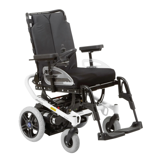
Page 7: Product Overview
Caster wheel Back support Drive wheel Arm support (side panel) Battery (2 battery packs) Control panel with joystick Mechanical back support angle adjustment (option) Seat cushion Plug with battery cable Quick-release lever for seat inclination adjust Anti-tipper ment Leg support A200... -
Page 8: Intended Use
Compliance with all manufacturer specifications and all applic able legal provisions is required. Please contact the manufacturer’s service department for further information (see inside or outside of rear cover for addresses). A200... -
Page 9: Safety
► Check your skin for intactness before and during use of the product. ► Pay attention to diligent skin care and pressure redistribution during interruptions in using the product. ► If skin damage or other problems occur during use, stop using the product. Consult the qualified personnel. A200... -
Page 10: Side Effects
Other types of hand-held devices, such as cordless phones, laptop computers, AM/FM radios, TV sets, CD players, and cassette players, and small appliances, such as electric shavers and hair dryers, so far as we know, are not likely to cause EMI problems to your powered wheelchair. A200... -
Page 11: Further Information
F Allowable axle load, front G Allowable axle load, rear H Allowable overall weight Manufacturer information/address Serial number K Manufacturing date L Symbol for medical device M WARNING! Read the instructions for use before using the product. Observe important safety-related information (e.g. warnings, precautions). A200... -
Page 12: Warning Labels
The power wheelchair is normally shipped fully assembled and fitted to the personal requirements of the respective user. The scope of delivery includes: • Fitted power wheelchair with main components • Installed options • Battery charger • Instructions for use • Instructions for use for accessories (depending on equipment) A200... -
Page 13: Storage
Crushing, pinching, blows due to non-observance of the maintenance and repair instructions ► Ensure that body parts, such as hands or head, are never in the danger zone. ► Perform the work with the aid of a helper for support. A200... -
Page 14: Initial Operation
All parts of the product should be cleaned thoroughly before adjustments are made. The tools required for adjustments and maintenance tasks as well as the torque values for screw connections are listed in the section "Appendices" (see Page 58). A200... -
Page 15: Safety Instructions
► Use only the original packaging for delivery of the product. 6.3.1.2 Adjusting the standard seat 6.3.1.2.1 Adjusting the back support upholstery INFORMATION A well-adjusted back support provides lasting comfort for the wheelchair user and reduces the risk of secondary damage and pressure zones. A200... -
Page 16: Inserting Foam Elements
► Adjusting the belt system too tightly may lead to unnecessary pain or user discomfort. ► Adjusting the belt system too loosely can cause the user to slide into a dangerous position. In addition, the fastening snaps could open unintentionally if they slide against hard parts of clothing (e.g. buttons). A200... -
Page 17: Adjusting The Control Device
Adjusting the lower leg length and foot support angle (see Page 20) • Adjusting the back angle (see Page 22) • Adjusting the position of the control panel (see Page 42) • Adjusting the lap belt (see Page 38) All parts of the product should be cleaned thoroughly before adjustments are made. A200... -
Page 18: Adjusting The Control Device
Note: The fuse typically comes installed in the dedicated fuse holder when the wheelchair is handed over to the user. Before the power wheelchair can be switched on, the fuses may have to be inserted into the fuse holders provided for the purpose. A200... -
Page 19: Side Panels
Adjusting the armrest to the forearm length 1) Loosen the 2 Allen head screws on the underside of the armrest (see fig. 7, item 2). 2) Push the armrest to the front or back into the desired position. 3) Tighten the 2 Allen head screws. A200... -
Page 20: Legrests
► Make sure that the leg supports and foot plates do not come into contact with the caster wheels under load. The legrests can be subsequently adjusted to the user's lower leg length. For some legrests, the angle of the foot plate can also be adjusted. A200... -
Page 21: Backrest
4) Check to ensure the lock is securely engaged by pulling on the back support. Folding down the back support 1) Pull on the strap until the locking bolts are free (see fig. 11). 2) Fold the back support down onto the seat. A200... -
Page 22: Adjusting The Back Support Angle
The modular design of the power wheelchair and the ease with which you can remove the side panels and legrests make it easy to get into and out of the wheelchair from the side or from the front. Users can choose the method for getting into and out of the wheelchair which is most suitable for them. A200... -
Page 23: Control Unit
The speed and driving direction are controlled with the joystick (see Page 28). [On/off] button Pressing this button turns the power wheelchair on or off (see Page 27). In combination with additional operating steps, it also activates/deactivates the drive-away lock (see Page 29). A200... -
Page 24: Driving Functions
See section "Maintenance/repair" > "Troubleshooting" (see Page 53) 8.7 Driving functions 8.7.1 Safety instructions Hazards while driving CAUTION Lack of riding experience Collision, falling due to errors in handling the product ► Practise using the product on level, open ground first. A200... - Page 25 Tipping over, falling of the user due to lifting on components that come loose or are not intended for lifting ► Only lift the product by firmly mounted components (e.g. on the main frame). ► Do not lift the product on components installed with screw connections, or on add-on or plug-on components (e.g. on the backrest of legrests, armrests). A200...
-
Page 26: Driving Notes
In order to navigate downhill gradients safely, the speed must be reduced according to the slope (e.g. select speed level 1). • Never drive downhill backwards. Only briefly manoeuvring on ramps is permitted (for example, when exiting a vehicle for transporting persons with reduced mobility). A200... -
Page 27: Switching On And Off
► If the driving function is still not available after turning the control device on again, pushing mode can be activ ated by releasing the brake (see Page 30). ► Consult the qualified personnel promptly if the driving function is not available after restarting. A200... -
Page 28: Selecting The Speed Levels
The further the joystick is deflected from the centre position, the faster the power wheelchair will drive in this direction. • The maximum speed at full deflection of the joystick depends on the selected speed level. • Releasing the joystick automatically activates the brake function, bringing the power wheelchair to a halt. A200... -
Page 29: Range
→ The drive-away lock is deactivated and driving is enabled. Troubleshooting The drive-away lock remains active if the deactivation movement is not completed correctly. 1) Turn the control device off in order to deactivate the drive-away lock again. 2) Turn the power wheelchair on. A200... -
Page 30: Adapting The Driving Characteristics
→ A warning appears on the control panel. Enabling/activating the brake 1) If needed: Turn the control device off. 2) Push the brake release lever up (see fig. 15, item 2). 3) Switch on the control device. → The driving function is activated. A200... -
Page 31: Batteries/Charging Process
NOTICE: Please also observe the information for charging the battery (see the next section). 8.9.3 Installing/removing the battery pack Removing and installing the battery packs is necessary to use the power wheelchair, insert or remove the fuse, and to replace the battery packs. A200... -
Page 32: Battery Charging Information
After charging the batteries, the circuit breaker should be deactivated if the wheelchair is not used for more than 3 days. • The power wheelchair control device must be switched off while the batteries are charging to allow all of the charging current to be fed into the battery. A200... -
Page 33: Battery Charger
Insufficient ventilation of the battery charger while charging Burns due to the battery charger overheating/catching fire ► Make sure the battery charger cannot overheat during the charging process. ► Ensure that the cooling fins/ventilation slots on the back of the device are not covered. A200... -
Page 34: Seat
► If the seat is expected to come into contact with liquid, such as spilt drinks or episodes of incontinence, always use it in conjunction with a liquid-repellent cover. ► Only use the Ottobock incontinence covers for this product. Contact the qualified personnel to obtain a spare Ottobock cover. A200... -
Page 35: Contoured Pads
Nevertheless, you should take the artificial leather cover off from time to time and check whether liquid has gotten into the foam pad through the seams. You should clean the foam pad if this is the case. The incontinence cover is positioned under the seat cover. It protects the foam pad against wetness. A200... -
Page 36: Cleaning The Covers
Detailed information regarding use, cleaning and maintenance can be found in the enclosed instructions for use for the seat cushion. 8.10.4 Adjusting the seat angle CAUTION Improper adjustments Falling of the user out of the seat due to user error ► The user must not sit in the wheelchair during seat angle adjustments. A200... -
Page 37: Headrest
► Please also observe the overriding safety instructions in the section "Manual seat functions" > "Safety instruc tions": see Page 37. The manual back angle adjustment feature enables the backrest to be tilted by up to 30°. The backrest can be tilted back incrementally to the angle specified above. A200... -
Page 38: Manually Elevating Legrests
Small length adjustments of the belt by the user or an attendant (e.g. for clothing of different thickness) are pos sible. The belt length can be adjusted on both sides. Excess belt length is taken up by the plastic slider. A200... -
Page 39: Use
► Do not leave the user unsupervised if the cognitive abilities of the user could lead to unintentional opening of the belt system. ► Information about subsequent acquisition and mounting is provided by the qualified personnel that handed the product over to you. A200... -
Page 40: Control Unit Accessories
Functional overview The attendant uses the attendant control to operate the driving function and the power seat functions. The module is connected in conjunction with the control panel or as a separate input device. A200... -
Page 41: Additional Options
1) Grasp the control panel holder on the front. 2) Pull the control panel holder off to the front. Installing the control panel holder 1) Insert the control panel holder into the rail. 2) Slide the control panel in to the rear. A200... -
Page 42: Adjusting The Control Panel Position
2) Slide the rail with the control panel forwards or backwards. INFORMATION: If the control panel rail is too long it can be shortened. Please contact the qualified personnel who adjusted your product. 3) Tighten the 3 set screws on the bottom of the arm rest. A200... -
Page 43: Overview Of Other Options
► Ensure that the seat is lowered all the way and the backrest is in a vertical position prior to loading and for transporting the power wheelchair. 8.15.2 Reducing the transportation size The transportation size can be reduced in a few steps to make transporting the product easier. A200... - Page 44 2) Fold the seat bottom down by simultaneously lifting the seat slightly and pushing the brackets to the rear. Make sure that the brackets are fully engaged in the respective locking position. 3) Firmly re-tighten the quick release levers after mak ing the adjustment. A200...
-
Page 45: Preparing For Transport
(frame protection rollers) above the anti-tip per rollers until these touch the ground (see fig. 35, left). The drive unit bracket is now at an angle. 4) Set the frame onto the drive unit bracket from above (see fig. 35, right). A200... -
Page 46: Use In Vehicles For Transporting Persons With Reduced Mobility
To use the power wheelchair as a seat in a vehicle for transporting persons with reduced mobility, additional accessories have to be mounted (491S00=SK024 anchor point kit). The qualified personnel who fitted the wheel chair can provide more information. A200... -
Page 47: Using The Product In A Vehicle
(see Page 30). 4) Apply the attachment straps (see below). Applying the front attachment straps 1) Hook each of the front attachment straps into its corresponding front anchor point from the outside (see fig. 42). 2) Tighten the front attachment straps. A200... - Page 48 Fastening the restraint lap belt 1) Guide each end of the restraint lap belt from the inner side of the seat to the outer side of the seat. 2) Engage the end of the restraint lap belt on the pin (see fig. 45). A200...
-
Page 49: Restrictions For Use
Do not spray the product with a pressure washer. • Observe additional cleaning instructions in the section "Lap belt": see Page 38. 8.17.3 Disinfection 1) Thoroughly clean the pads before disinfecting. 2) Wipe all parts of the product with a disinfectant. A200... -
Page 50: Maintenance And Repair
Seat attachment Check whether mounting screws are fastened properly Leg support Check ratchet mechanism for functionality and firm fit Check for damage to foot supports Check ratchet mechanism for functionality and firm fit Check for damage to foot supports A200... -
Page 51: Repair
9.2.1 Replacing a defective fuse INFORMATION When replacing, only use fuses of the same type. Note the printed rating. To replace a fuse: see Page 18. Should the fuse burn out repeatedly after a short time for no discernible reason, contact the qualified personnel. A200... -
Page 52: Wheel Replacement
6) Repair the inner tube with a standard tyre repair kit or replace it. 7) Reassemble the rim. Firmly tighten the screws. 8) Reinstall the wheel (see previous section). 9.2.4 Replacing the battery The battery packs may only be replaced by qualified personnel. A200... -
Page 53: Troubleshooting
Wiring fault on the left e.g. cable break, no con Check cable connections to left motor nection to battery motor; check connection to battery terminal Right motor not connec e.g. defective plug con Check plug connections and cable nection, cable break to right motor A200... -
Page 54: Attendant Control Error Overview
To get help faster, noting the address and telephone number of the responsible specialist dealer in the field provided on the back of these instructions for use is recommended. This information should be kept on hand, especially when driving outdoors. A200... -
Page 55: Disposal
Ottobock stores, processes and uses the data accord ing to the applicable data protection regulations. For detailed questions please contact: datenschutz@ottobock.de. For questions regarding treatment, please con tact the qualified personnel. 11.4 Service life Expected lifetime: 5 years A200... -
Page 56: Technical Data
Battery, removable: approx. 11 kg (24.2 lbs; each) Max. load 100 kg (220 lbs) (permissible user weight) Model with standard seat, Junior: 75 kg (165.3 lbs) Turning radius 870 mm (34.2") Turning circle** 1290 mm (50.8") Caster wheel tyre size 8" (puncture-proof) Drive wheel tyre size 12" (pneumatic); optional 12" (puncture-proof) A200... - Page 57 ***** The braking distance can be correspondingly longer due to user weight, installed options and condition of the tyres as well as weather and surface conditions. Allowable environmental conditions Operating temperature -15 °C to +40 °C (+5 °F to +104 °F) Transport and storage temperature -15 °C to +40 °C (+5 °F to +104 °F) Relative humidity 45% to 85%; non-condensing Corrosion protection A200...
-
Page 58: Appendices
► The products in the series were tested for compliance with maximum sound emission requirements according to the ISO 7176-14 standard. ► They fully meet the requirements according to the areas of application identified below. Area of application Maximum sound pressure level In enclosed rooms 65 db(A) A200... - Page 59 Appendices Area of application Maximum sound pressure level Outside of enclosed rooms 75 db(A) Depending on the area of application according to ISO 7176-14 A200...
- Page 60 A200...
- Page 61 A200...
- Page 62 A200...
- Page 63 · www.ottobock.de 143441 Moscow Region/Krasnogorskiy Rayon info@ottobock.com.co · www.ottobock.com.co Russian Federation Otto Bock Healthcare Products GmbH Otto Bock de Mexico S.A. de C.V. T +7 495 564 8360 · F +7 495 564 8363 Brehmstraße 16 · 1110 Wien · Austria Prolongación Calle 18 No. 178-A info@ottobock.ru · www.ottobock.ru F +43 1 5267985...
- Page 64 Ihr Fachhändler | Your specialist dealer Otto Bock Mobility Solutions GmbH Lindenstraße 13 · 07426 Königsee/Germany www.ottobock.com...
Need help?
Do you have a question about the A200 and is the answer not in the manual?
Questions and answers