Otto Bock A 200 Instructions For Use Manual
Hide thumbs
Also See for A 200:
- Instructions for use manual (142 pages) ,
- Service instructions manual (64 pages) ,
- Using manual (152 pages)

Related Manuals for Otto Bock A 200


Summary of Contents for Otto Bock A 200
- Page 1 A 200 Bedienungsanleitung............3 . Instructions.for.Use.............21 © Otto Bock · 647G214=D/GB – 02.09/5 – Printed in Germany...
-
Page 3: Table Of Contents
Instructions for Use Contents Page 1 Preface .................................22 2 Field of Application ............................22 3 Liability .................................22 4 CE Conformity ..............................22 5 Service .................................22 6 Safety Instructions ............................23 7 Transport and Storage ..........................24 7.1 Transport in a Motor Vehicle ......................24 7.2 Disassembling the A200 Power Wheelchair .................. -
Page 4: Preface
This device meets the requirements of the 93 / 42 / EEC guidelines for medical devices. This device has been classified as a class I device according to the classification criteria outlined in appendix IX of the guidelines. The declaration of conformity was therefore created by Otto Bock with sole responsibility according to appen- dix VII of the guidelines. -
Page 5: Safety Instructions
Note: Please ensure your A200 power wheelchair is checked and serviced at least ONCE a year by an authorised dealer! 6 Safety Instructions To avoid potentially dangerous situations such as tipping, you must become familiar with the power wheelchair on level ground first. When getting into or out of the power wheelchair, the wheelchair control must be switched off. -
Page 6: Transport And Storage
For the time being, Otto Bock has not yet released the A200 Power Wheelchair for use as a seat for transportion in motor vehicles; the release is currently being prepared, however. - Page 7 5. Release the seat lock by simultaneously pulling the release strap and folding the locking bar to the rear (Fig. 2). 6. Remove the battery packs by releasing the Lock Lever (Fig. 6). 7. Separate the frame from the drive unit assembly. Place your weight on the mounting of the anti-tipper above the wheels so the wheels touch the ground (Fig.
-
Page 8: Adjustment Possibilities
Delivery Upon delivery by the dealer the A200 is ready for use. All settings have been made in accordance with the indi- cations on the order form or are made directly on site by the dealer. Thus, the A200 is adapted to the personal requirements of the individual. -
Page 9: Seat Angle Adjustment
8.2 Seat Angle Adjustment The A200 offers seat angle settings in 3 different positions (0°, 3° and 6°). For setting the position, 2 quick re- lease levers are used which are located at the front below the seat. To change the seat angle, loosen the two quick release levers. -
Page 10: Footrest
8.5 Footrest Figure 13 Figure 14 To remove the footrest, the calf band must be unhooked first. Now it is easy to release the footrest lock and then swing away the footrest either inwards or outwards as shown in figure 13. When in this position, the foot- rest can be pulled upwards and removed. -
Page 11: Putting Into Operation
If necessary the footrests can also be removed completely (see section 7.5). With the assistance of an attendant or by means of a transfer lifter, the user can get into or out of the wheelchair from the front. Use of a rotation plate is also possible. 10 Putting into Operation The wheelchair control can be adapted to your personal requirements. -
Page 12: Brake Release
10.3 Brake Release In case of failure of the control unit or insufficient battery capacity, it is possible to push the A200. To do this, the brake must be released using the mechanical release mechanism. Figure 16 The control will recognise that the brake has been released and automatically deactivate the driving function. Note: After locking the brake release lever into the pushing position, all brake systems are switched off. -
Page 13: Charging
This results in the following information regarding "correct" use of the battery indicator: • Batteries are charged • Charge the batteries if possible • Battery charging is urgently required Figure: Battery indicator Immediately after switching on, the LEDs show the battery capacity status saved before the wheelchair was switched off the last time. -
Page 14: Batteries
• The warranty is void in case of damages that result from a totally discharged battery! • When the A200 is not used over extended periods of time it must be charged once a week. • Only the battery charger provided by Otto Bock may be used for charging. Note: During battery charging, the control must be switched off. -
Page 15: Fuse
Attention! Regularly checking of the remaining battery capacity and charging of the battery early enough are indispensable preconditions for the operational safety of your power wheelchair. Figure 18 Figure 19 10.9 Fuse The two 60 A fuses are located at the rear end of the battery packs between the battery‘s contacts (Fig. 19). 11 Status and Error Analysis The following table lists the different error and status messages of the battery indicator and describes the cor- responding possible causes and solutions. -
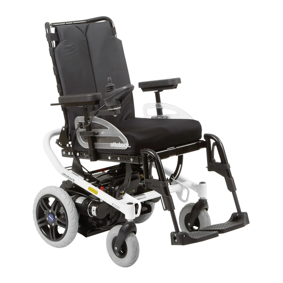
Page 16: A200 Standard Version
Fast flashing of LEDs 1-7 Joystick error Joystick in mid-position when switching on Fast flashing of LEDs 1-8 Error of control unit Check the plug connection Fast flashing of LEDs 1-9 Brake has been released Lock the brake or check the motor plug connection Fast flashing of LEDs 1-10 Overvoltage on the control unit... -
Page 17: Cleaning
To be checked daily weekly monthly Tyres Tyre air pressure (printed on the sidewall of the tyre) Condition of tyres Batteries Battery capacity Electronics >> each time before driving << Control without error message? Does the battery charger show any error messages on the LEDs? If you have any problems carrying out this maintenance, please contact your authorised dealer (see section 4 "Service"). -
Page 18: Technical Data Of The A200
16 Technical Data of the A200 Measurements and weights Seat width: 38 - 42 cm Seat depth: 38 - 46 cm Seat height: 43 / 48 cm Armrest height: 24 - 36 cm Armrest length: 26 cm Lower leg length: Standard seat 25 - 45 cm Contoured seat 28 - 53 cm Back height: 45 or 55 cm Backrest angle:... -
Page 19: Technical Data Of The Battery Charger
17 Technical Data of the Battery Charger Automatic battery charger with computer-controlled characteristic curve for 24 V sulfuric acid batteries. Power requirements: 230 V AC Mains frequency: 50 Hz Protection class: II, insulated twice Charging connection: 24 VDC Nominal charging current: max. 5A programmable Protective system: IP 54 Weight: approx. - Page 21 Tel. +44 1784 744900 · Fax +44 1784 744901 Otto Bock HealthCare India Pvt. Ltd. e-mail: bockuk@ottobock.com · www.ottobock.co.uk Behind Fairlawn Housing Society Otto Bock Ortopedi ve Rehabilitasyon Tekniği Ltd. Şti. Sion Trombay Road Ali Dursun Bey Caddesi · Lati Lokum Sokak Otto Bock France SNC Chembur ·...
- Page 22 Phone +49 69 9999 9393 · Fax +49 69 9999 9392 ccc@ottobock.com · www.ottobock.com Otto Bock Mobility Solutions GmbH has been certified by the German Society for the Certification of Quality Assurance Systems (DQS) in accordance with DIN EN ISO 9001 standard, reg. no. 779 (management system)
Need help?
Do you have a question about the A 200 and is the answer not in the manual?
Questions and answers