Otto Bock Avantgarde CV Service Manual
Hide thumbs
Also See for Avantgarde CV:
- Instructions for use manual (32 pages) ,
- Service manual (56 pages) ,
- Instructions for use manual (36 pages)
Table of Contents
Advertisement
Quick Links
Advertisement
Table of Contents

Related Manuals for Otto Bock Avantgarde CV


Summary of Contents for Otto Bock Avantgarde CV
- Page 1 Avantgarde CV / CS / CLT Service manual...
-
Page 2: Table Of Contents
Replacing the Tube Foot Rest ....................... 3.7.3.5 Replacing the Tube Foot Rest Mounting ....................Assembly C: seat, seating system ......................3.8.1 Replacing the Standard/Business Seat Upholstery .................. 3.8.2 Replacing the Seat Upholstery, Adaptable ..................... Avantgarde CV / CS / CLT... - Page 3 Replacing/Retrofitting a Spoke Protector ....................3.12.6.3 Tensioning the spokes; adjusting the out-of-round ................... 3.12.6.4 Adjusting the Quick-Release Axle ......................3.12.6.5 Retrofitting the Tetra Axle ........................3.12.6.6 Inner tube, rim tape and tyre replacement ....................Avantgarde CV / CS / CLT...
- Page 4 Retrofitting a Tray ..........................3.14.3 Retrofitting a fixation kit ........................3.14.3.1 Installing the 481S64=SK010 fixation kit (Avantgarde CS) ................ 3.14.3.2 Installing the 481S64=SK015 fixation kit (Avantgarde CV) ................ Technical data ..............................Appendices ................................ Torque values of the screw connections ....................Maintenance Schedule ........................
-
Page 5: Introduction
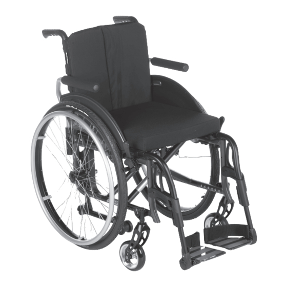
Your national Ottobock team will be happy to answer any technical questions. The contact addresses and tele phone numbers can be found on the back inside cover of the service manual. 1.3 Product overview Avantgarde CS Avantgarde CV / CS / CLT... - Page 6 Maximum load (in combination with double cross-brace): 140 kg Thanks to its frame geometry, the Avantgarde CV offers precise leg guidance with the possibility of swinging away and removing the foot rests. When the foot rests are removed, the upright frame front section allows the wheelchair to be manoeuvred close to objects.
- Page 7 11 Double cross-brace 4 Back tube 12 Caster wheel 5 Push handle 13 Caster fork 6 Rear frame 14 Foot rest 7 Front frame 15 Knee lever wheel lock 8 Rear wheel attachment device (here welded) Avantgarde CV / CS / CLT...
-
Page 8: Safety
If new screws or nuts with thread lock are not available, use a medium strength liquid thread locking compound (e.g. Loctite® 241 or Euro Lock A24.20). Avantgarde CV / CS / CLT... -
Page 9: Instructions For Adjustment
4) Unscrew and remove the caster wheel assembly from the lower frame tube (see fig. 4). → The lower frame tube is detached from the rear part of the frame. 5) Lay the wheelchair on its back and unscrew the upper frame tube (see fig. 5). Avantgarde CV / CS / CLT... -
Page 10: Replacing The Rear Frame Part
7) Remove the rear part of the frame rearward (see fig. 10). 8) Remove all parts (back tubes, supports) installed on the frame. 9) To reassemble, perform these steps in reverse order. Tighten the frame tubes with 23 Nm. Avantgarde CV / CS / CLT... -
Page 11: Replacing The Cross-Brace/Cross-Brace Bracket
6) To reassemble, perform these steps in reverse order. Tighten the centre screw to the point that folding without jamming is possible. 3.6.1.4 Replacing the Joint Tubes 1) Remove the front part of the frame (see Page 9). 2) Unscrew the rear wheel adapter and remove (see Page 9). Avantgarde CV / CS / CLT... -
Page 12: Replacing The Seat Tube Supports
→ Thread a nut from above into the profile of the vertical accessory mount (see fig. 21, item 2). → Hold the nut (see fig. 21, item 3) and tighten the screw from the outside to 7 Nm. Avantgarde CV / CS / CLT... -
Page 13: Installing And Adjusting The Anti-Tipper
The anti-tipper can be installed at 5 positions on the vertical accessory mount (see fig. 22, item 1). 1) Push the anti-tipper tube from below into the vertical accessory mount. Avantgarde CV / CS / CLT... -
Page 14: Replacing The Pivot Arm
2) Adjust the height of the pivot arm (see fig. 22, item 2). → The distance between the anti-tipper rollers and the ground must be max. 50 mm (2 inch) (see fig. 25). 3) Tighten the Allen head screw to 7 Nm. Avantgarde CV / CS / CLT... -
Page 15: Retrofitting The Transport Wheels
2) Insert the transport wheel true to side into the vertical accessory mount. 3) Adjust the height of the transport wheels (see fig. 30). Adjust the height so that the transport wheels are approx. 20 mm above the ground when the rear wheel is installed. Avantgarde CV / CS / CLT... -
Page 16: Retrofitting The Horizontal Accessory Mount
2) Insert the tip-assist true to side (see fig. 34). 3) Tighten the clamp's mounting screw to 8 Nm. 3.6.7 Retrofitting the Crutch Holder ► Set the crutch holder onto the tip-assist and screw it in place. Avantgarde CV / CS / CLT... -
Page 17: Retrofitting The Frame Pads (Cs/Clt Only)
2) Push the swivel handle of the foot rest to the rear. 3) Swing the foot rest outwards and to the side by 90° (see fig. 39). 4) Remove the foot rest upward and replace (see fig. 40). 5) To reassemble, perform these steps in reverse order. Avantgarde CV / CS / CLT... -
Page 18: Replacing The Foot Rest Bar/Swivel Segment
2) Unscrew the size 4 Allen head screws on the angle adjustment (see fig. 44). 3) Replace the foot plate. 4) To reassemble, perform these steps in reverse order. Tighten the Allen head screw to 10 Nm. Avantgarde CV / CS / CLT... -
Page 19: Replacing The Pivot Bearing
1) Remove the foot rest. 2) Unscrew the Phillips head screw on the heel strap holder (see fig. 47). 3) Remove/replace the heel strap holder and the heel strap. 4) To reassemble, perform these steps in reverse order. Avantgarde CV / CS / CLT... -
Page 20: Elevating Foot Rest With Automatic Length Adjustment
2) Select one of the 3 threaded bores. INFORMATION Depending on the setting it may be necessary to add or remove one or more spacer sleeves. 3) Insert the Allen head screw. 4) Tighten the Allen head screw to 8 Nm. Avantgarde CV / CS / CLT... -
Page 21: Replacing The Calf Pads
2) Remove and replace the foot rest bar (see fig. 55). 3) The foot rest bar must be pushed at least 40 mm into the swivel segment. 4) Tighten the Allen head screw to a torque of 10 Nm. Avantgarde CV / CS / CLT... -
Page 22: Replacing The Foot Plate
5) Position the tube foot rest in place and tighten the Allen head screw to 10 Nm. 6) Set the width of the tube foot rest by adjusting the screw (see fig. 60). 7) Flip down the tube foot rest and close the lateral cover for the angle adjustment. Avantgarde CV / CS / CLT... -
Page 23: Replacing The Tube Foot Rest Mounting
5) Remove/replace the upholstery bar (see fig. 67). 6) Replace the seat upholstery. 7) To reassemble, perform these steps in reverse order. 8) If necessary, adjust the seat upholstery with the aid of the upholstery strap hook-and-loop connector (see fig. 68). Avantgarde CV / CS / CLT... -
Page 24: Cleaning The Seat Upholstery
2) Clean the cover according to the attached care label. 3) Wash all foam parts by hand at 40°C using a mild, environmentally friendly detergent. Allow to air dry. 4) Reinsert the foam core with proper alignment. Close the zip. Avantgarde CV / CS / CLT... -
Page 25: Assembly D: Back/Push Handle
1) Remove the old push handle. 2) Slide the "height-adjustable/removable" push handle onto the back tube. 3) Insert the installation adapter into the back tube (see fig. 75). 4) Bolt the installation adapter together with the push handle (see fig. 76). Avantgarde CV / CS / CLT... -
Page 26: Retrofitting The "Folding" Push Handles
NOTICE! Once the processing time (pot life) has expired, the adhesive is hardened and the push handle can no longer be moved or adjusted. 6) Allow the adhesive to harden for approx. 24 h before handing the wheelchair over to the user. Avantgarde CV / CS / CLT... - Page 27 NOTICE! Once the processing time (pot life) has expired, the adhesive is hardened and the hand grip can no longer be moved or adjusted. 7) Allow the adhesive to harden for approx. 24 h before handing the wheelchair over to the user. Avantgarde CV / CS / CLT...
-
Page 28: Replacing The Back Upholstery
2) Remove the side panels. 3) Remove the back pad. 4) Open the uppermost strap and remove/replace (see fig. 85). 5) Remove/replace other straps (see fig. 86). 6) To reassemble, perform these steps in reverse order. Avantgarde CV / CS / CLT... -
Page 29: Replacing The Back Tubes
4) Tighten all mounting screws on the rear frame to 7 Nm. 5) Finally, adjust the angle on both back tubes in the same way (see fig. 92). CAUTION! Ensure that the mounting screw is loosened enough to avoid damage to the ratchet mech anism. Avantgarde CV / CS / CLT... -
Page 30: Assembly E: Side Panels
6) Securely retighten all the screws. 7) Push on the rear wheel and ensure that it can rotate freely. → After adjustment of both side panels, both rear wheels must rotate freely without scraping noises. Avantgarde CV / CS / CLT... -
Page 31: Replacing The Side Panel Mounting
3.10.2 Replacement Work on the Desk Side Panel 3.10.2.1 Replacing the Desk Side Panels 1) Remove/replace the desk side panel. 2) Insert the desk side panel in the side panel mounting and fold downward. Avantgarde CV / CS / CLT... -
Page 32: Replacing The Side Panel Mounting
2) Unscrew the size 5 Allen head screw on the retaining clip (see fig. 105). 3) Replace/position/bolt down the retaining clip. 3.10.2.5 Replacing the Pivot Pin 1) Remove the side panel. 2) Unscrew the 2 Phillips head screws on the pivot pin (see fig. 106). Avantgarde CV / CS / CLT... -
Page 33: Replacing The Strut
1) Unscrew/remove the caster head mounting on the frame (2x size 6 Allen head screws) (see fig. 111). 2) Remove the caster head adapter and the caster head (see fig. 112). 3) To reassemble, perform these steps in reverse order. Tighten the screw connection evenly with 23 Nm. Avantgarde CV / CS / CLT... -
Page 34: Replacing The Caster Head
6) Tighten the Allen head screw on the eccentric to 8 Nm (CLT: 5.5 Nm) (see fig. 116). 7) Tighten the Allen head screws on the inside of the frame to 23 Nm. → The threaded axle on both caster wheel adapters must be positioned vertically. Avantgarde CV / CS / CLT... -
Page 35: Replacing/Changing The Installation Position Of The Caster Wheels
6) Push on the 2nd spacer bush (see fig. 120, item 1). 7) Tighten the threaded axle to 8 Nm. → Once changed, the left and right caster wheel must have the same vertical position in the caster wheel fork. Avantgarde CV / CS / CLT... -
Page 36: Replacing The Caster Fork
Allen head screws. In doing so, install the longer screw in the rear in travel direction. 4) Tighten the Allen head screws to 6 Nm. 5) Finally, adjust the caster wheel journal angle (see fig. 125; see Page 33). Avantgarde CV / CS / CLT... -
Page 37: Retrofitting The Seat Height Adapter
5) Install the caster head with 23 Nm: → Position A: for high front seat heights (see fig. 130). → Position B: for low front seat heights (see fig. 131). 6) Adjust the caster wheel journal angle (see Page 34). Avantgarde CV / CS / CLT... -
Page 38: Assembly G: Rear Wheels
→ before installation exchange the left rear wheel adapter for the right. 5) Insert the lock rings and tighten the Allen head screws to 7 Nm. → Once changed, the left and right rear wheel adapter must have the same horizontal position on the frame. Avantgarde CV / CS / CLT... -
Page 39: Installing The Fitting
5) Insert the spirit level holder into the groove. Insert the spirit level and align the camber washers upright (see fig. 139). 6) Tighten the nuts on both sides of the fitting to 50 Nm. → Once changed, the left and right fittings must both have the same vertical position in the rear wheel adapter. Avantgarde CV / CS / CLT... -
Page 40: Shock Absorber System
5) Adjust the shock absorber depth. Use the bores in the frame for orientation (see fig. 143, item 1). 6) Tighten the clamping screws to 8 Nm (see fig. 143, item 2). → Once changed, the left and right shock absorber must have the same horizontal position on the frame. Avantgarde CV / CS / CLT... -
Page 41: Installing The Fitting
6) Bolt down the wheelbase extension on the bottom rear part of the frame with size 4 Allen head screw, washer and size 10 cap nut (see fig. 149). Torque = 23 Nm. 7) Finally, push the protective caps onto the hex nuts (see fig. 150). Avantgarde CV / CS / CLT... -
Page 42: Installing The Fitting
• Wheelchair becomes more manoeuvrable, turns faster and tips less easily to the side • The wheel position protects the hands when turning the push ring • Overall width increases • Increased rolling resistance Avantgarde CV / CS / CLT... -
Page 43: Changing The Rear Wheel Camber With A Rear Wheel Adapter
8) With the help of the spirit level, align the camber washers vertically (see fig. 156, arrows). 9) Tighten the hexagon nuts to 50 Nm. → After adjustment, the camber of the left and right rear wheels must have the same angle. Avantgarde CV / CS / CLT... -
Page 44: Maintenance Work On The Rear Wheel
3) From the outside, press in the attachment nipples e.g. with a hammer handle until you hear them lock in place on the spokes (see fig. 159). INFORMATION: Screw connections are required for installation in some versions (see fig. 160). Avantgarde CV / CS / CLT... -
Page 45: Tensioning The Spokes; Adjusting The Out-Of-Round
2) Adjust the play by turning the nut on the end of the quick-release axle (size 19; see fig. 161, item 1) in or out. 3.12.6.5 Retrofitting the Tetra Axle 1) Remove the quick-release axle with rear wheel. 2) Exchange quick-release axle for tetra axle. 3) Insert rear wheel with tetra axle into the fitting. Avantgarde CV / CS / CLT... -
Page 46: Inner Tube, Rim Tape And Tyre Replacement
4) Insert the tube into the tyre. 5) Mount the other side of the tyre on the rim, starting from the position across the valve. Ensure that the tube is not pinched between the tyre and rim during this process. Avantgarde CV / CS / CLT... -
Page 47: Assembly H: Wheel Lock/Brake
4) Adjust the knee lever wheel lock. When the wheel lock is disengaged, the gap between the tyre and wheel lock bolt must not exceed 5 mm (see fig. 170). 5) Tighten the Allen head screws to 6 Nm. → After adjustment, the left and right knee lever wheel locks must both have the same braking force. Avantgarde CV / CS / CLT... -
Page 48: Replacing The Brake Block
10) Shorten the Bowden cable to 1 cm after making the adjustments (see fig. 181). 11) Attach the cable end sleeve to the end of the Bowden cable. Avantgarde CV / CS / CLT... -
Page 49: Retrofitting The Drum Brake
In order to use rear wheels equipped with a drum brake, the standard fitting must be replaced with a mounting plate with fitting, and brake handles and Bowden cables must be installed on the wheelchair. Avantgarde CV / CS / CLT... -
Page 50: Adjusting The Braking Force Of The Drum Brake
2) Screw in the adjustment screw (see fig. 184, item 2) until the scraping noise at the rear wheel disappears and the wheel runs freely. 3) Tighten the counter nut (see fig. 184, item 1) until the adjustment screw is fixed. → The braking force of both rear wheels must be adjusted equally. Avantgarde CV / CS / CLT... -
Page 51: Retrofitting The Scissor Wheel Lock
(see fig. 185, item 3). INFORMATION: Use new Allen head screws or secure the existing Allen head screws with liquid thread locking compound. 7) Tighten the Allen head screws on the clamp fitting to 15 Nm. Avantgarde CV / CS / CLT... -
Page 52: Adjusting The Wheel Locks
3) Install the scissor wheel lock so that the full braking force is reached and the swivelling parts can also move freely without colliding. → The scissor wheel lock must not hit the frame when it is open. Avantgarde CV / CS / CLT... - Page 53 Special Requirements for Adjustments (All Types of Wheel Locks) Depending on the adjustment, it may be necessary to rotate or replace the support for the wheel lock. This makes further wheel lock adjustments possible. Avantgarde CV / CS / CLT...
-
Page 54: Additional Options
4) Screw the included pins onto the retaining plates on the left and right sides (see fig. 195, item 1). → The fixation kit is installed. Avantgarde CV / CS / CLT... -
Page 55: Installing The 481S64=Sk015 Fixation Kit (Avantgarde Cv)
Service Work 3.14.3.2 Installing the 481S64=SK015 fixation kit (Avantgarde CV) The 481S64=SK015 fixation kit is intended for installation on the Avantgarde CV. Required tools • Ring spanners, sizes 10 and 13 • Allen keys, sizes 4 and 5 Assembly 1) Screw 1 anchor plate to each side of the front frame. The securement brackets and hook symbols face out... -
Page 56: Technical Data
Rear axle Front axle Rear axle position position position position position position 1000 1010 1020 1005 1030 1040 1025 1050 1060 1005 1015 1045 1070 1080 With wheelbase extension: rear axle position + 95 mm. Avantgarde CV / CS / CLT... - Page 57 1030 1040 With wheelbase extension: rear axle position +95 mm. On Avantgarde CLT, fixed welded variant: rear axle position -20 mm. Avantgarde CV/CS/CLT – overall width with rear wheel with hollow rim 1), 2), 3) [mm] Seat width Side panels, standard and clothing protector Desk side panel with armrest, height- adjustable Applicable to push rim attachment, narrow and a 0°...
- Page 58 From position E, the rear wheel adapter must be turned around (see fig. 200): right side to the left side and left side to the right side. Avantgarde CLT, fixed welded variant: for the exact values for "rear seat height", see 647F105* order form. Avantgarde CV / CS / CLT...
-
Page 59: Appendices
5.1 Torque values of the screw connections Unless otherwise specified, screw connections are tightened with the following torque values: • Thread diameter M4: 3 Nm • Thread diameter M5: 5 Nm • Thread diameter M6: 10 Nm • Thread diameter M8: 25 Nm Avantgarde CV / CS / CLT... -
Page 60: Maintenance Schedule
Shock absorber Wheel locks / brakes Braking function Swing-away mechanism Wheel lock accessories Wheel lock lever extension Accessories Tray Lap belt Do the wheelchair settings match the user's requirements? The maintenance service was performed by: Avantgarde CV / CS / CLT... - Page 61 Avantgarde CV / CS / CLT...
- Page 62 Avantgarde CV / CS / CLT...
- Page 63 · www.ottobock.de 143441 Moscow Region/Krasnogorskiy Rayon info@ottobock.com.co · www.ottobock.com.co Russian Federation Otto Bock Healthcare Products GmbH Otto Bock de Mexico S.A. de C.V. T +7 495 564 8360 · F +7 495 564 8363 Brehmstraße 16 · 1110 Wien · Austria Prolongación Calle 18 No. 178-A info@ottobock.ru · www.ottobock.ru F +43 1 5267985...
- Page 64 Ihr Fachhändler | Your specialist dealer Printed by: Otto Bock Mobility Solutions GmbH Lindenstraße 13 · 07426 Königsee-Rottenbach/Germany www.ottobock.com...
Need help?
Do you have a question about the Avantgarde CV and is the answer not in the manual?
Questions and answers