Taylor-Dunn B0-T48-48 Taylor Truck T48 Operation Manual
Hide thumbs
Also See for B0-T48-48 Taylor Truck T48:
- Operation, t roubleshooting and replacement parts manual (242 pages) ,
- Manual (196 pages)
Table of Contents
Advertisement
Quick Links
Advertisement
Chapters
Table of Contents
Troubleshooting

Related Manuals for Taylor-Dunn B0-T48-48 Taylor Truck T48


Summary of Contents for Taylor-Dunn B0-T48-48 Taylor Truck T48
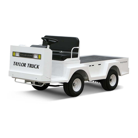
- Page 1 Taylor Truck ET 3000 Models Inlcuded: B0-T48-48 Taylor Truck (T48) ET-030-48 (ET 3000) T h e B e s t W a y T o G o A b o u t Y o u r B u s i n e s s MANUAL MB-T48-01 Operation, Troubleshooting and Re- placement Parts Manual...
- Page 3 No part of this work may be reproduced or transmitted in any form or by any means, electronic or mechanical, including photocopying and recording, or any information storage or retrieval system without prior written permission of Taylor-Dunn Mfg. unless such copying is expressly permitted by federal copyright law. Address inquiries to Reference Permissions, Taylor-Dunn Mfg., 2114 W.
-
Page 5: Table Of Contents
TABLE OF CONTENTS INTRODUCTION Operator and Maintenance Manual Introduction ..............ii How To Use This Manual ............iii Who Should Read This Manual ..........iv Responsibilities ............... iv Conventions ................v SECTION 1 Vehicle Description and Specifications Vehicle Description ............2 Standard Specifications ............. - Page 6 SECTION 3 Maintenance and Service Procedures Maintenance Guidelines ..........2 Severe Duty Guidelines ..........3 Periodic Maintenance Checklist ......... 4 Lubrication Chart ............5 Troubleshooting Guide ..........6 Brakes ..................7 Brake Pad Replacement ..........9 Repairing the Brake Body ........10 Bleeding the Brakes ..........
- Page 7 SECTION 4 Electrical and Charger Troubleshooting Sevcon Controller Troubleshooting ......2 Voltage Reference Table ........... 25 LED Status Chart ............26 Lestronic II Charger Troubleshooting ......1 Operating Instructions and Theory of Operation Lester Lestronic II Battery Charger ........2 Testing the Charging Cycle ............
- Page 8 Motor ................22 Automatic Electric Brake ..........24 Instrument Panel and Components......26 Resetting the Smart View Display ......27 Control Panel .............. 28 Electrical Components (typical) ......... 30 Lester Charger............. 32 Signet Charger ............34 Accelerator Module ............ 36 Drive ................
- Page 9 SECTION 5B Illustrated Parts List ET 3000 Standard Parts Tire & Wheel Assemblies, and Tire & WheelComponents ......2 Standard Parts .............. 4 Standard Parts Cab Interior, Dash, and Seat Switch ....6 Standard Parts, Aluminum Side Panel Option and Deck Board Option ........8 Box with Doors ............
-
Page 11: Operator And Maintenance Manual
INTRODUCTION Operator and Maintenance Manual... - Page 12 Introduction The purchase of this vehicle shows a belief in high quality products manufactured in the USA. Taylor-Dunn , a leading manufacturer of electric burden and personnel carriers since 1949, wants to be sure this vehicle provides years of reliable service. Please...
-
Page 13: How To Use This Manual
MB-T48-01 How To Use This Manual This manual is organized into five main sections: SECTION 1: Vehicle Description and Specification This section describes the vehicle and operation of this particular vehicle, as well as the responsibilities of the operator. SECTION 2: Safety Rules and Operational Information This section outlines the safety and operational issues, location and operation of controls, and the operational checks that are to be performed on this vehicle. -
Page 14: Who Should Read This Manual
At no time should a service person allow any untrained personnel to service or repair this or any Taylor-Dunn vehicle. For the purposes of training, a qualified service person may oversee the repairs or services being made to a vehicle by an individual in training. -
Page 15: Conventions
MB-T48-01 Conventions Symbols and/or words that are used to define warnings, cautions, instructions, or notes found throughout this manual: A shaded box with the word “Warning” on its left denotes a warning. A warning alerts the reader of a hazard that may result injury to themself or others. - Page 16 MB-T48-01 INTRODUCTION PAGE vi...
-
Page 17: Vehicle Description And Specifications
SECTION 1 Vehicle Description and Specifications... -
Page 18: Vehicle Description
MB-T48-01 Vehicle Description This manual applies to the models and serial numbers listed on the front cover. This vehicle is designed for driving on The model number for this vehicle is imprinted smooth surfaces in and around industrial on a decal located under the right side seat on plants, nurseries, institutions, motels, the top of the front inner fender (Figure 1). -
Page 19: Standard Specifications
MB-T48-01 Standard Specifications ITEM SPECIFICATION Occupancy 2 Passenger Dimension Taylor Truck 318L X 127W X 119H Centimeters 125L X 50W X 47H Inches ET 3000 325L X 127W X 191H Centimeters 128L X 50W X 75H Inches Turning Radius 368 Centimeters 145 Inches Dry Weight Taylor Truck... -
Page 20: Taking Delivery Of The Vehicle
MB-T48-01 Taking Delivery of the Vehicle Inspect the vehicle immediately after delivery. Use the following guidelines to locate obvious problems: • Examine the contents of all packages and accessories that may have come in separate packages with the vehicle. Make sure everything listed on the packing slip •... - Page 21 MB-T48-01 Check the operation of each of the following controls: Accelerator • • Brake Parking Brake • Key-Switch • • Forward/Reverse Switch with Reverse Beeper • Front Headlight Switch Steering Wheel • • Horn SECTION 1 PAGE 5...
-
Page 22: What To Do If A Problem Is Found
What To Do If a Problem is Found If there is a problem with the vehicle, DO NOT OPERATE THE VEHICLE, file a claim with a local Taylor-Dunn distributor. The claim must be filed within 48 hours of receiving the vehicle and its accessories. -
Page 23: Safety Rules And Operational Information
SECTION 2 Safety Rules and Operational Information... -
Page 24: Safety Rules And Guidelines
MB-T48-01 Safety Rules and Guidelines This vehicle is designed for driving on smooth surfaces in and around industrial plants, nurseries, institutions, motels, mobile home parks, and resorts. It is not intended for use on public streets and highways. It is the responsibility of the owner of this vehicle to assure that the operator understands the various controls and... - Page 25 MB-T48-01 Before driving this vehicle, please observe the following safety rules and guidelines: • Only qualified and trained operators shall drive this vehicle. • Drive only on level surfaces or on surfaces having an incline of less than 10% (5.6 degrees). •...
-
Page 26: Driver Training Program
MB-T48-01 DRIVER TRAINING PROGRAM The owner of this vehicle should conduct an Operator Training Program for all those who will be operating this vehicle. The training program should not be condensed for those claiming to have previous vehicle operation experience. Successful completion of the Operator Training Program should be required for all... -
Page 27: Driver Qualifications
MB-T48-01 DRIVER QUALIFICATIONS The following are minimum requirements necessary to qualify as an operator of this vehicle: Demonstrate a working knowledge of each control. • • Understand all safety rules and guidelines as presented in this manual. Know how to properly load and unload •... -
Page 28: Vehicle Controls
MB-T48-01 VEHICLE CONTROLS Key-Switch A key-switch, located on the right side of the instrument panel, turns on the vehicle. Rotate the key clockwise to turn the vehicle power on, counterclockwise to turn the vehicle power off. The key-switch should be in the “OFF” position whenever the operator leaves the driver's seat. -
Page 29: Steering
MB-T48-01 Steering The steering wheel and steering system is similar to an automobile. To turn right, turn the steering wheel towards the right. To turn left, turn the steering wheel towards the left. Foot Brake Pedal The foot brake pedal, located to the right of the steering column, is for operation with the right foot only. -
Page 30: Seat Interlock Switch
MB-T48-01 Seat Interlock Switch A switch located under the driver's seat disables the power to the vehicle when the driver leaves the seat. The driver must be seated for the vehicle to operate. Whenever the driver leaves the seat, they should turn the key-switch off, place the forward-reverse switch in the center “OFF”... -
Page 31: Battery Status Indicator
MB-T48-01 Battery Status Indicator The battery status indicator is located to the left of the hour meter. The battery status indicator has a LED bar graph that indicates the relative state of charge of the battery. The top LED will light only when connected to a fully charged battery or after completing a charging cycle. -
Page 32: Smart View Display
MB-T48-01 Smart View Display The Smart View Display (SVD) functions as a Battery Status Indicator (BSI), Hour Meter (HM), speed controller status monitor, and as an optional maintenance monitor feature. The operation of each of these functions is listed below. BSI: A bar graph representing the current state of charge is located across the top of the display. - Page 33 MB-T48-01 Run Time Hours: After the initial 5-seconds, the Run Time Hours will be displayed as indicated by the Run Time Hours Indicator located at the left of the display. The icon represents a motor symbol with a “T” in the center. Run Time Hours icon Speed controller status: The display will indicate a fault code whenever the control system logic...
- Page 34 MB-T48-01 Maintenance monitor: Operation: The SMD notifies the operator 10-hours (standard) before a scheduled maintenance is due. During this warning period, the meter will continue to alert the operator. This should allow sufficient time for the operator to schedule the maintenance that is due, with minimal down time. If the scheduled maintenance is not performed before the warning period elapses, then the vehicles maximum speed will be significantly reduced.
-
Page 35: Vehicle Operational Guidelines
MB-T48-01 Vehicle Operational Guidelines Driving • Slow and sound the horn to warn pedestrians or when approaching a corner or other blind intersection. No reckless driving. • Do not drive this vehicle on steep inclines or where • forbidden. Immediately report any accident or vehicle problem •... -
Page 36: Storing And Returning To Service
MB-T48-01 Storing and Returning to Service 1. Make sure the key-switch is in the “OFF” position, then remove the key. 2. Place the forward-reverse switch in the center “OFF” position. 3. Set the park brake. 4. Place blocks under the front wheels to prevent vehicle movement. -
Page 37: Maintenance And Service Procedures
SECTION 3 Maintenance and Service Procedures... -
Page 38: Maintenance Guidelines
MB-T48-01 Maintenance Guidelines Allow only qualified and authorized personnel to maintain, repair, adjust, or inspect the vehicle. •Before starting any repairs or maintenance, immobilize the vehicle. •Turn the key switch “OFF” and remove the key. •Set the park brake. •Place the forward-reverse switch in the center “OFF”... -
Page 39: Severe Duty Guidelines
MB-T48-01 Avoid fire hazards and have fire protection equipment present in the work area. Do not use an open flame to check level or leakage of battery electrolyte, also battery gas emissions are explosive . Do not use open pans of fuel or flammable fluids for cleaning parts. Ventilate the work area properly. -
Page 40: Periodic Maintenance Checklist
MB-T48-01 Periodic Maintenance Checklist Maintenance Item Weekly Monthly Quarterly Semi- Annually (20 hrs) (80 hrs) (250 hrs) Annually (1000 hrs) (500 hrs) Check Condition of Tires Check & Fill Batteries Check Brake System Check Steering System Check for Oil Leaks Lubricate Vehicle Clean &... - Page 41 MB-T48-01 Lubrication Description Locations Lubricant Type Steering ball joints General Purpose Grease Prake pedal linkage General Purpose Grease Front wheel bearings General Purpose Grease K ing pin General Purpose Grease Drive drain plug Drive fill/level plug SAE 80w90 Gear Oil NOTE: The drive fluid level should be filled to the bottom edge of the fill level plug threads.
-
Page 42: Troubleshooting Guide
MB-T48-01 TROUBLESHOOTING GUIDE Symptom Probable Cause Front End Out of Alignment Steering Pulls in One Direction Low Tire Pressure Dry Lube Points in Steering Linkage Hard Steering Damaged King Pin/Ball Joint Low Tire Pressure Worn Ball Joints Excessive Steering Play Mis-Adjusted or Worn Steering Gear Loose Steering Linkage Brakes or Parking Brakes Dragging... - Page 43 MB-T48-01 Hydraulic Disc Brakes SECTION 3 PAGE 7...
- Page 44 MB-T48-01 Taylor-Dunn does not currently supply asbestos fiber- brake pads/shoes with any vehicle. However, there is the possibility that the original brake pads/shoes were replaced with aftermarket pads/shoes containing asbestos. Since this possibility does exist, the brake pads/shoes should be handled as if they do contain asbestos.
-
Page 45: Brake Pad Replacement
MB-T48-01 BRAKE PAD REPLACEMENT 1. Make sure the key-switch is in the “OFF” position, then remove the key. 2. Place the forward-reverse switch in the center “OFF” position. 3. Set the park brake. 4. Place blocks under the front wheels to prevent vehicle movement. -
Page 46: Repairing The Brake Body
MB-T48-01 Repairing the Brake Body 1. Make sure the key-switch is in the “OFF” position, then remove the key. 2. Place the forward-reverse switch in the center “OFF” position. 3. Set the park brake. 4. Place blocks under the front wheels to prevent vehicle movement. - Page 47 MB-T48-01 10. Remove the brake body. 11. Carefully remove the rubber boots, two pistons, and o-rings. NOTE: The pistons are very brittle and break easily. 12. Clean and dry the brake body completely. NOTE: Inspect the interior of the brake body. (If any damage or wear is found, it must be replaced) Make sure there are no contaminants left in the brake body.
-
Page 48: Bleeding The Brakes
MB-T48-01 Bleeding the Brakes 1. Make sure the key-switch is in the “OFF” position, then remove the key. 2. Place the forward-reverse switch in the center “OFF” position. 3. Set the park brake. 4. Place blocks under the front wheels to prevent vehicle movement. - Page 49 MB-T48-01 9. With a drip pan under the hydraulic brake body, loosen the bleeder valve on the hydraulic brake body about 3/4 of a turn. 10. Depress the foot pedal to the floor while tightening the bleeder valve. 11. Slowly release the foot pedal, allowing it to return to its released position.
-
Page 50: Replacing The Master Cylinder
MB-T48-01 Replacing the Master Cylinder 1. Make sure the key-switch is in the “OFF” position, then remove the key. 2. Place the forward-reverse switch in the center “OFF” position. 3. Set the park brake. 4. Place blocks under the rear wheels to prevent vehicle movement. -
Page 51: Filling And Checking The Fluid Level
MB-T48-01 Filling and Checking the Fluid Level 1. Make sure the key-switch is in the “OFF” position, then remove the key. 2. Place the forward-reverse switch in the center “OFF” position. 3. Set the park brake. 4. Place blocks under the front wheels to prevent vehicle movement. -
Page 52: Parking Brake
MB-T48-01 PARKING BRAKE SECTION 3 PAGE 16... - Page 53 MB-T48-01 Park Brake Adjustment 1. Make sure the key-switch is in the “OFF” position, then remove the key. 2. Place the forward-reverse switch in the center “OFF” position. 3. Set the park brake. 4. Place blocks under the rear wheels to prevent vehicle movement.
-
Page 54: Front Axle And Yokes
MB-T48-01 FRONT AXLE AND YOKES SECTION 3 PAGE 18... -
Page 55: Axle Removal And Installation
MB-T48-01 Front Axle Removal and Installation 1. Make sure the key-switch is in the “OFF” position, then remove the key. 2. Place the forward-reverse switch in the center “OFF” position. 3. Set the park brake. 4. Place blocks under the rear wheels to prevent vehicle movement. -
Page 56: Aligning The Front End
MB-T48-01 Aligning the Front End Adjusting the Toe-In 1. Make sure the key-switch is in the “OFF” position, then remove the key. 2. Place the forward-reverse switch in the center “OFF” position. 3. Set the park brake. 4. Place blocks under the front wheels to prevent vehicle movement. -
Page 57: Centering The Steering
MB-T48-01 Centering the Steering Gear 1. Make sure the key-switch is in the “OFF” position, then remove the key. 2. Place the forward-reverse switch in the center “OFF” position. 3. Set the park brake. 4. Place blocks under the front wheels to prevent vehicle movement. -
Page 58: Repairing The Front Axle
MB-T48-01 Repairing the Front Axle Steering Yoke/Bushings 1. Make sure the key-switch is in the “OFF” position, then remove the key. 2. Place the forward-reverse switch in the center “OFF” position. 3. Set the park brake. 4. Place blocks under the rear wheels to prevent vehicle movement. - Page 59 MB-T48-01 10. While supporting the yoke, remove the nylock nut, washers, and rubber washer. 11. Remove the yoke from the axle. 12. Clean and/or replace all bearings, nuts, washers, and bushings. NOTE: Both the left and right side bushings should be replaced as a set. 13.
-
Page 60: Ball Joints, Tie Rods, And Drag Links
MB-T48-01 Ball Joints, Tie Rods, And Drag Links It is recommended to replace the left and right side ball joints as a set. 1. Make sure the key-switch is in the “OFF” position, then remove the key. 2. Place the forward-reverse switch in the center “OFF” position. 3. -
Page 61: Front Wheel Bearings
MB-T48-01 Seal Bearing Bearing race Bearing race Bearing Cotter pin Spindle nut Dust Cap Washer Wheel Hub Assembly Front Wheel Bearings 1. Make sure the key-switch is in the “OFF” position, then remove the key. 2. Place the forward-reverse switch in the center “OFF” position. 3. - Page 62 MB-T48-01 9. Remove the hub from the axle yoke. NOTE: For a front disc brake option remove the brake body before removing the hub. NOTE: Catch the outer bearing as it falls out. 10. Clean all grease from the inside of the hub and bearings. 11.
-
Page 63: Removal And Installation Of The Steering Gear
MB-T48-01 Removal and Installation of the Steering Gear Assembly 1. Make sure the key-switch is in the “OFF” position, then remove the key. 2. Place the forward-reverse switch in the center “OFF” position. 3. Set the park brake. 4. Place blocks under the rear wheels to prevent vehicle movement. - Page 64 MB-T48-01 11. Reinstall the steering gear by performing this procedure in reverse order. Always use new locknuts and bolts. Locknuts and bolts become less effective if used more than once. If the locknuts or bolts holding the steering gear assembly come loose, serious bodily injury may occur.
-
Page 65: Steering Gear Adjustment
MB-T48-01 Steering Gear Adjustment Input Shaft Endplay 1. Make sure the key-switch is in the “OFF” position, then remove the key. 2. Place the forward-reverse switch in the center “OFF” position. 3. Set the park brake. 4. Place blocks under the rear wheels to prevent vehicle movement. -
Page 66: Gear Lash
MB-T48-01 Gear Lash 1. Make sure the key-switch is in the “OFF” position, then remove the key. 2. Place the forward-reverse switch in the center “OFF” position. 3. Set the park brake. 4. Place blocks under the rear wheels to prevent vehicle movement. - Page 67 MB-T48-01 REPAIR THE STEERING GEAR Disassembly NOTE: The steering gear must be removed from the vehicle for this procedure. Refer to Replace the Steering Gear section for information regarding removing the steering gear. NOTE: The steering gear is packed with grease. Only perform mainte- nance on the steering gear in an area that will contain any grease that may spill out of the steering gear when it is disassembled.
- Page 68 MB-T48-01 4. Remove the worm shaft and ball nut assembly from the bottom of the housing. 5. Remove the worm shaft seal. 6. Remove the pitman shaft seal. 7. Remove the upper worm bearing and bearing cup from the housing. 8.
- Page 69 MB-T48-01 9. Place the upper worm bearing on the worm shaft and install the worm shaft/ball nut assembly into the housing being careful not to damage the worm shaft seal. 10. Install the assembled worm bearing adjuster into the housing and tighten just enough to remove all play in the worm shaft.
- Page 70 MB-T48-01 SECTION 3 PAGE 34...
-
Page 71: Drive Service
MB-T48-01 DRIVE SERVICE SECTION 3 PAGE 35... -
Page 72: Removing The Rear Axles
MB-T48-01 Removing the Rear Axles This procedure does not require that the rear end or drive assembly be removed from the vehicle. 1. Make sure the key-switch is in the “OFF” position, then remove the key. 2. Place the forward-reverse switch in the center “OFF” position. 3. - Page 73 Removing the Rear Axles (Continued) 16. Use new bolts for the axle retaining plate. Use new Taylor-Dunn (96-327-10) bolts for the axle retaining plate. The bolts have a manufactured thread patch applied to each bolt. Failure to use proper bolts may cause the axle to fall out of the truck and cause property damage and or serious bodily injury.
-
Page 74: Removing And Installing The Drive
MB-T48-01 Removing and Installing the Drive from the Vehicle 1. Make sure the key-switch is in the “OFF” position, then remove the key. 2. Place the forward-reverse switch in the center “OFF” position. 3. Set the park brake. 4. Place blocks under the front wheels to prevent vehicle movement. -
Page 75: Reduction Gear Case
MB-T48-01 D i s a s s e m b l i n g a n d R e a s s e m b l i n g o f t h e P r i m a r y Reduction Gear Case 1. - Page 76 MB-T48-01 9. Remove the cover retaining bolts. Do not damage the housing sealing surface or deform the cover plate. This will cause leaks destroy the gears, bearings and races Failure to do so will void any and all warranties. 10. Remove the cover plate from the differential let the remaining oil drain from the housing.
- Page 77 NOTE: Be sure to apply gasket sealer to the front flange on the 3rd member and gear case cover. Be sure to use Taylor-Dunn Sealant 94-430-05. NOTE: Pack the motor seal with non-acetic based grease. 19. Fill the differential with 3-5 oz. of oil.
-
Page 78: Assembly Of The 3Rd Member
MB-T48-01 Disassembling the 3rd Member 1. Make sure the key-switch is in the “OFF” position, then remove the key. 2. Place the forward-reverse switch in the center “OFF” position. 3. Set the park brake. 4. Place blocks under the front wheels to prevent vehicle movement. - Page 79 MB-T48-01 13. Remove the carrier bearing adjusting nut roll pin and adjusting nut from the side plate. 14. Turn the side plate over and remove the carrier bearing race. 15. Remove the differential assembly. 16. Remove the carrier bearing adjusting nut roll pin from the 3rd member housing, then remove the carrier adjusting nut.
- Page 80 MB-T48-01 17. Remove the carrier bearing race. 18. Remove the front bearing from the input shaft. NOTE: The input shaft may have to be driven out to perform this procedure. 19. Remove the input shaft’s shims and spacer. 20. Remove the input shaft. 21.
- Page 81 MB-T48-01 Assembling the 3rd Member Be sure to pre-lube all of the bearings. Failure to do so will cause early wear, damage and void any and all warranties. If the pinion gear, bear- ings, races or the ring and pinion were re- placed, the pinion gear must be re-shimmed.
- Page 82 MB-T48-01 7. Remove the pinion gear. 8. Reinstall the differential assembly. 9. Install the cover onto the housing using 4-bolts in a cross pattern and torque to 45-50 ft-lbs. 10. Pre set the carrier bearing preload by tightening thehousing carrier bearing race ring nut until it requires 1.5 to 3.3 ft-lbs to rotate the differential assembly.
- Page 83 MB-T48-01 15. Install the cover and all of the cover bolts. Torque the bolts to 45-50 foot pounds. Failure to do so will result in early wear and tear on components and void any and all warranties. 16. Check the gear lash between the ring and pinion gears.
-
Page 84: Pinion Gear Shimming
MB-T48-01 Pinion Gear Shimming Instructions NOTE: This is required only when replacing the front or rear pinion bearings and races or the ring and pinion gears. NOTE: All parts must be clean and the bearings lightly lubricated. Pinion Gear Depth and Selecting the Pinion Shim C - B - A + (D ) = Pinion Shim (mm) = The number on the face of the pinion gear. -
Page 85: Pinion Bearing Preload
MB-T48-01 NOTE: Numbers are for reference only. Once a shim has been selected and the pinion gear is installed, confirm: E - D = B + (D Pinion Bearing Preload 1. The pinion gear depth must be set before the preload. 2. -
Page 86: Changing The Differential Oil
MB-T48-01 Changing the Differential Oil 1. Make sure the key-switch is in the “OFF” position, then remove the key. 2. Place the forward-reverse switch in the center “OFF” position. 3. Set the park brake. 4. Place blocks under the front wheels to prevent vehicle movement. -
Page 87: Speed Controller
MB-T48-01 SPEED CONTROLLER SECTION 3 PAGE 51... -
Page 88: Removing And Installing Speed Controller
11. Bolt the controller and heat sink together between the control panel. NOTE: A small amount of heat sink paste should ooze out from both the controller and heat sink. Be sure to use Taylor-Dunn Heatsink Paste 94-422-20. 12. Reassemble the control panel harnesses. Replace the electronics splash cover. -
Page 89: Drive Motor
MB-T48-01 DRIVE MOTOR SECTION 3 PAGE 53... -
Page 90: Motor Removal
MB-T48-01 Motor Removal It is not necessary to remove the drive assembly to perform this procedure in most cases. However, if the vehicle is equipped with an optional cargo box, it may be necessary to lower the drive assembly in order to access the motor. -
Page 91: Automatic Electric Brake Removal And Installation
MB-T48-01 Automatic Electric Brake Removal and Installation In the event, a vehicle equipped with, an automatic electric brake unit becomes immobile. Tow the vehicle with the rear axle hoisted and secured in the air to the maintenance facility were an authorized technician can begin any necessary repairs. It is not necessary to remove the drive assembly to perform the removal and installation of the electric brake in most cases. - Page 92 MB-T48-01 Automatic Electric Brake Removal and Installation ( Continued ) 8. Slide the automatic electric brake off the drive input shaft. 9. Repair or replace components as necessary. 10. Install the new motor or reassemble in reverse order. NOTE: Apply a small amount of grease to the input shafts. 11.
-
Page 93: Motor Disassembly And Assembly
MB-T48-01 Motor Disassembly and Assembly 1. Make sure the key-switch is in the “OFF” position, then remove the key. 2. Place the forward-reverse switch in the center “OFF” position. 3. Set the park brake. 4. Place blocks under the front wheels to prevent vehicle movement. - Page 94 MB-T48-01 15. Remove the nuts from the A1 and A2 terminals M o t o r I n n e r and the brush holder retaining screws, then remove Bearing Race the brush holder assembly from the commutator end cap. NOTE: Be sure to remember the position of the cross over wires.
-
Page 95: Armature And Brush Inspection
MB-T48-01 Armature and Brush Inspection 1. Make sure the key-switch is in the “OFF” position, then remove the key. 2. Place the forward-reverse switch in the center “OFF” position. 3. Set the park brake. 4. Place blocks under the front wheels to prevent vehicle movement. -
Page 96: Motor Specifications
MB-T48-01 11. Measure the undercut depth on the commutator. See Undercut Figure Below. NOTE: The undercut depth is .025 inches. If the undercut depth is less then .025 inches, the mica can be recut to the proper depth. 12. Inspect the brushes for damage and wear. NOTE: The minimum brush length is 5/8”. -
Page 97: Battery
MB-T48-01 BATTERY SECTION 3 PAGE 61... -
Page 98: Cleaning
MB-T48-01 Cleaning 1. Make sure the key-switch is in the “OFF” position, then remove the key. 2. Place the forward-reverse switch in the center “OFF” position. 3. Set the park brake. 4. Place blocks under the front wheels to prevent vehicle movement. -
Page 99: Electrolyte Alarm
MB-T48-01 Electrolyte Alarm (Optional) 1. Make sure the key-switch is in the “OFF” position, then remove the key. 2. Place the forward-reverse switch in the center “OFF” position. 3. Set the park brake. 4. Place blocks under the front wheels to prevent vehicle movement. -
Page 100: Servicing
MB-T48-01 Servicing 1. Make sure the key-switch is in the “OFF” position, then remove the key. 2. Place the forward-reverse switch in the center “OFF” position. 3. Set the park brake. 4. Place blocks under the front wheels to prevent vehicle movement. -
Page 101: Charging
MB-T48-01 Charging 1. Make sure the key-switch is in the “OFF” position, then remove the key. 2. Place the forward-reverse switch in the center “OFF” position. 3. Set the park brake. 4. Place blocks under the front wheels to prevent vehicle movement. - Page 102 MB-T48-01 SECTION 3 PAGE 66...
- Page 103 Sevcon Control System Troubleshooting TABLE OF CONTENTS Test Equipment Required: ...... 2 Important Notes and Instructions ... 2 Definitions: ..........2 Terminology used: ........2 Start Troubleshooting Here ....3 Test 8. Anti-Rolloff Fault ......22 Test 9. Electric Motor Brake ....23 Sevcon Logic Voltage Reference Table ...
- Page 104 Electrical Troubleshooting Test Equipment Required: • Digital multimeter (DMM) with diode test function, FLUKE 79 model shown. • Test harness, Taylor-Dunn #75-089-00 Important Notes and Instructions • This troubleshooting guide assumes a familiarity with the use of a digital multimeter including, voltage tests, continuity tests, and diode testing.
- Page 105 Electrical Troubleshooting START TROUBLESHOOTING HERE This troubleshooting guide is written in sequential order. All tests must be performed in the order that they are written. Starting in the middle or skipping sections when not instructed to do so may lead to invalid test results.
- Page 106 Electrical Troubleshooting Test 1. CHECKING THE CONTROL LOGIC INPUTS Close the seat switch. Place the high/low switch in the HIGH position. Connect a voltmeter across the ISO solenoid coil terminals and carefully monitor the voltage as the key switch is turned on. Turn the key switch ON and wait 1-second until the Isolator contactor closes.
- Page 107 Electrical Troubleshooting TEST 1.3: Test the voltage at pin #6 on the 12-pin logic card connector. If the voltage is low, then skip ahead to test #1.4. If the voltage is high, then check the wire to the High/Low switch and the High/Low switch for open circuits.
- Page 108 Electrical Troubleshooting TEST 1.5: Test the voltage at pin #4 on the 12-pin logic card connector. If the voltage is high, then skip ahead to test #1.6. If the voltage is low, then skip ahead to Test #6. TEST 1.6: Test the voltage at pin #7 on the 12-pin logic card connector.
- Page 109 Electrical Troubleshooting TEST 1.7: Depress the accelerator pedal to engage FS-1 only (creep speed). Perform the following tests: Test the voltage at pin #10 on the 12-pin logic card connector. If the voltage is below 0.3 volts, then skip ahead to test #1.8.
- Page 110 Electrical Troubleshooting Test 2. TESTING THE MOTOR 1. Make sure the key-switch is in the “OFF” position, then remove the key. 2. Place the forward-reverse switch in the center “OFF” position. 3. Set the park brake. 4. Place blocks under the front wheels to prevent vehicle movement. Disconnect both of the battery leads during any maintenance or before disconnecting any electrical component or wire.
- Page 111 Electrical Troubleshooting TEST 2.3: Test the continuity from the motor A1 terminal to the frame on the motor and from F1 to A1 for open circuits. Any reading other than an open circuit indicate a short in the motor. If there is a short in the motor, stop here and repair or replace the motor.
- Page 112 Electrical Troubleshooting Test 3. THE VEHICLE RUNS IN ONE DIRECTION ONLY Test 3.1: Close the seat switch, turn the key switch ON and wait 1-second until the Isolator contactor closes. If the vehicle runs in reverse only then skip ahead to test #3.3.
- Page 113 Electrical Troubleshooting TEST 3.3: Place the forward and reverse switch in the REVERSE direction. Test the voltage at pin #3 on the 12 pin logic card connector. If the voltage is low, then skip ahead to test #3.4. If the voltage is high, then skip ahead to Test #7. TEST 3.4: Test the voltage at pin #2 on the 12 pin logic card connector.
- Page 114 STOP Stop, do not continue. Reaching this point indicates an unanticipated failure or an error was made during testing. Confirm all previous tests were performed correctly and contact your Taylor-Dunn represetative for assistatnce. ® After any repairs are made, completely retest the vehicle before lowering the drive wheels to the ground.
- Page 115 Electrical Troubleshooting Test 4. KEY FAULT TEST 4.1: Turn the key switch ON and place the forward and reverse switch in the center OFF position Perform the following tests: Test the voltage at pin #1 on the 12 pin logic card connector.
- Page 116 Electrical Troubleshooting TEST 4.3: Test the voltage at the cold side (violet/black wire) of the key switch. If the voltage equals battery volts, then skip ahead to test #4.4. If the voltage does not equal battery volts, then replace the key switch. Stop trouble shooting here and repair the problem.
- Page 117 Electrical Troubleshooting Test 5. CONTACTOR COIL FAULT Disconnect the 12-pin logic card connector from the Sevcon power unit. Turn the key switch ON and perform the following tests: TEST 5.1: Check the voltage on the positive coil terminal of the ISO solenoid (violet wire).
- Page 118 Electrical Troubleshooting B+ Terminal on the Sevcon controller Shorted Solenoid Coil: Disconnect the logic card connector and measure the resistance across the solenoid coil. Depending on the solenoid or contactor you vehicle is equipped with, the resistance should be 25 ohms or higher (nominal). A reading less than 25 ohms may indicate a shorted coil.
- Page 119 Electrical Troubleshooting Test 6. ACCELERATOR MODULE FAULT Disconnect the truck harness from the accelerator module. Connect the plug on the short end of the 75-089-00 test harness to the accelerator module. Connect the receptacle on the short end of the test harness to the vehicles control harness. The long end of the harness will be used for testing.
- Page 120 Electrical Troubleshooting TEST 6.2: Accelerator pedal released. Test the voltage from pin #9 to pin #8. If the voltage equals battery volts, then skip ahead to test #6.3. If the voltage does not equal battery volts, then check the wire from pin #8 to the key switch. Stop trouble shooting here and repair the problem.
- Page 121 Electrical Troubleshooting TEST 6.5a: Test the voltage from pin #5 to pin #8. Accelerator pedal released. If the voltage is low then skip ahead to test 6.5b. If the voltage is high then then the module has failed. Stop trouble shooting here and repair the problem. When the repair is completed, completely retest the vehicle before lowering the drive wheels to the ground.
- Page 122 Electrical Troubleshooting Test 7. FORWARD AND REVERSE SWITCH FAULT Turn the key switch ON, place the forward and reverse switch in the center OFF position and perform the following tests: TEST 7.1: Referencing battery positive, test the voltage on the center terminal of the F&R switch (Black wire).
- Page 123 Electrical Troubleshooting TEST 7.3: If the vehicle does not travel in forward, skip ahead to test #7.4. Place the forward and reverse switch in the REVERSE position. Referencing battery positive, test the voltage at the White/ Black wire on the F&R switch. If the voltage equals battery volts, skip ahead to test #7.4.
- Page 124 Electrical Troubleshooting Test 8. ANTI-ROLLOFF FAULT The Sevcon Controller is equipped with a feature called Anti-Rolloff. Anti-Rolloff will automatically slow the vehicle if it starts to roll. Anti-Rolloff is active when the key switch has been left in the “ON” position and the accelerator pedal is not depressed. Anti-Rolloff is deactivated when the key switch is in the “OFF”...
- Page 125 Electrical Troubleshooting Test 9. ELECTRIC MOTOR BRAKE Description: The electric motor brake is a 24-volt electromagnetic disc brake mounted between the drive motor and the primary reduction gear case. The brake is controlled by the speed controller logic. At what times the brake is applied or released is dependent on the controller programing and will vary depending on the model vehicle.
- Page 126 Electrical Troubleshooting Connect a volt meter from battery negative to the Violet/Black wire at the electric brake harness plug. If the voltage is less than battery volts then: • Check wiring to the key switch and continue troubleshooting at test #4.2. If the voltage equals battery volts then: Connect a volt meter across the Violet/Black wire and the Blue wire at the electric brake harness plug.
- Page 127 Electrical Troubleshooting Sevcon Logic Voltage Reference Table Pin# Condition Volts* Key switch off 0.0 volts Key switch on Battery volts F&R in forward F&R in neutral High F&R in reverse F&R in reverse F&R in neutral High F&R in forward Accelerator pedal up High Accelerator pedal down...
- Page 128 Electrical Troubleshooting Status LED Code Table The status LED on the Sevcon power unit logic card can be used to give you an idea of where the problem may be. It is recommended that you complete the troubleshooting procedure to confirm failure of any component.
- Page 129 Lestronic II Charger Troubleshooting ® TABLE OF CONTENTS Operating Instructions and Theory of Operation ......2 Testing the Charging Cycle ....3 Test Equipment Required for Troubleshooting ......4 Important Notes and Instructions -------------------- 4 Troubleshooting for Built-in Charger ..5 Troubleshooting for Portable Charger ..8 Testing The Timer Relay ......9 Testing the Interlock Relay .....10 Turn the Key switch OFF BEFORE disconnecting the batteries.
-
Page 130: Operating Instructions And Theory Of Operation
Electrical Troubleshooting OPERATING INSTRUCTIONS AND THEORY OF OPERATION The Lestronic II chargers are designed as semiautomatic chargers. The Lestronic II charger turns itself ® ® on when the “built- in” charger is plugged into the wall outlet, or when the “portable” charger is plugged into the batteries. -
Page 131: Testing The Charging Cycle
Electrical Troubleshooting TESTING THE CHARGING CYCLE In typical installations, the charger will remain on for up to 12 hours depending on the state of charge of the battery when the charge cycle was started. A charger could remain on for longer than 12 hours if: •... -
Page 132: Test Equipment Required
Electrical Troubleshooting TEST EQUIPMENT REQUIRED FOR TROUBLESHOOTING Digital Multi Meter (DMM) with diode and capacitor test function, FLUKE 79 model ® shown at right and in the troubleshooting illustrations. Important Notes and Instructions • This troubleshooting guide assumes a familiarity with the use of a digital multimeter including, voltage tests, continuity tests and diode testing. -
Page 133: Troubleshooting For Built-In Charger
Electrical Troubleshooting TROUBLESHOOTING FOR BUILT-IN CHARGER 1. Make sure the key-switch is in the “OFF” position, then remove the key. 2. Place the forward-reverse switch in the center “OFF” position. 3. Set the park brake. 4. Place blocks under the front wheels to prevent vehicle movement. 5. - Page 134 Electrical Troubleshooting • Disconnect the charger from the AC source. • Disconnect the batteries. • Disconnect the charger from the vehicle’s harness. • Remove the charger from the vehicle. HIGH VOLTAGE may be stored in the capacitor. Discharge the capacitor before continuing.
- Page 135 Electrical Troubleshooting • Test the voltage from the fuse assembly (-) to the diode block (+). This voltage should be equal to the battery voltage. If the voltage is less than the battery voltage, then the wires from the harness connectors to the charger are bad.
-
Page 136: Troubleshooting For Portable Charger
Electrical Troubleshooting TROUBLESHOOTING FOR PORTABLE CHARGER Disconnect the charger from the AC outlet and the batteries. 1. Test the voltage from the positive terminal on the vehicles DC receptacle to main battery negative. This voltage should be equal to the battery voltage. If the voltage is less than the battery voltage then this wire is broken or has a bad connection. -
Page 137: Testing The Timer Relay
Electrical Troubleshooting 5. Reconnect the lead to the diode. 6. Connect the charger to the AC source. Insert the DC charger plug into the DC receptacle and perform the following tests: High Voltage inside the charger. Do not touch any internal components while the charger is plugged in. -
Page 138: Testing The Interlock Relay
Electrical Troubleshooting 4. Disconnect the wires from the contact terminals on the timer relay. 5. Reconnect the batteries. 6. Wait 5 seconds, then test the continuity across the timer relay contact terminals. • If this is a closed circuit, then the timer start up circuit is functioning normally. •... -
Page 139: Signet Charger Troubleshooting
Signet Charger Troubleshooting ® TABLE OF CONTENTS Operating Instructions and Theory of Operation ........2 Testing the Charging Cycle ....3 Test Equipment Required for Troubleshooting .......4 Important Notes and Instructions Status LED Error Code ......5 Troubleshooting ........6 Turn the Key switch OFF BEFORE disconnecting the batteries. Disconnecting the batteries with the key switch ON may corrupt the controller programming resulting in a fault code 1 (refer to fault table). - Page 140 Electrical Troubleshooting OPERATING INSTRUCTIONS AND THEORY OF OPERATION The model HB600W and HB1000W chargers are designed as semiautomatic chargers. The charger ® ® turns itself on when it is plugged into the wall outlet and turns off when the batteries are fully charged. Both the HB600W and HB1000W are two stage chargers.
-
Page 141: Testing The Charging Cycle
Electrical Troubleshooting TESTING THE CHARGING CYCLE In typical installations, the charger will remain on for up to 14 hours depending on the state of charge of the battery when the charge cycle was started. A charger could remain on for longer than 14 hours if: •... - Page 142 Electrical Troubleshooting TEST EQUIPMENT REQUIRED FOR TROUBLESHOOTING Digital Multi Meter (DMM) with diode and capacitor test function, FLUKE 79 model ® shown at right and in the troubleshooting illustrations. Clamp on DC ammeter to measure up to 20-Amps. Important Notes and Instructions •...
-
Page 143: Status Led Error Code
Electrical Troubleshooting STATUS LED ERROR CODE There are three status lights (LED’s) on the charger name plate. These LED’s normally indicate the current operating state of the charger. All three LED’s flashing indicate an error in the charger. See the table below for an explanation if the error codes: Error Description... -
Page 144: Troubleshooting
Electrical Troubleshooting TROUBLESHOOTING To test charger operation: Connect a DC volt meter to the main battery positive and negative terminals. Attach a clamp on DC Ammeter to one of the charger DC output wires. Plug the charger into an AC outlet. After 5 or 6 seconds, the ammeter should display the DC Amp rating of the charger (plus or minus 10%) indicating that the charger is on (constant current mode). - Page 145 Wire Diagrams TABLE OF CONTENTS Complete Vehicle ..........2 Dash ..............3 Control Panel ..........4 Accelerator Module Detail ......5 Lighting ............6...
-
Page 146: Wire Diagrams
Wire Diagrams COMPLETE VEHICLE R. TURN R. TAIL LIGHT Blue/White Green White White BLACK White View from pin side White Brown BLACK Brown Brown HEAD LIGHTS Yellow Blue/White Brown Blue Green Green Black Gray Black/Gray Gray Yellow Blue BRAKE LIGHT YELLOW White White... -
Page 147: Control Panel
Wire Diagrams CHARGER CHARGER Black CORD NOTE: The charger INTERLOCK interlock may be located in CHARGER the charger cabinet. GREEN GREEN WHITE GROUND GROUND BATTERY POSITIVE Black BATTERY NEGATIVE Blue 12V NEGATIVE TAP Black Yellow Green MOTOR White Blue White White White CONTROL... -
Page 148: Throttle Module
Wire Diagrams DASH DASH PANEL HORN BUTTON B- Out Blue/White B- In LIGHT B- In Brown SWITCH PC Board B+ In Brown 0-5V Out SWITCH Special order accesories may be wired to this terminal Throttle module SWITCH Harness Connector Throttle module shown for Violet/ Black reference only. -
Page 149: Lighting
Wire Diagrams LIGHTING R. TURN R. TAIL LIGHT Blue/White Green White White BLACK View from pin side White White Brown BLACK Brown Brown HEAD LIGHTS Yellow Blue/White Brown Blue Green Green Black Gray Black/Gray Gray Yellow Blue BRAKE LIGHT YELLOW White White Black... - Page 150 Electrical Troubleshooting Section 4 Page 37...
-
Page 151: Illustrated Parts List Common
SECTION 5 Illustrated Parts List Common Front axle assembly ........5-2 Steering Sleeve Assembly ......5-4 Front Suspension ........5-6 Drag Link ..........5-8 Steering Gear ..........5-10 Steering Column Assembly ....... 5-12 Master Cylinder, brake line hardware and front brake Asssembly ....... 5-14 Master Cylinder ........ -
Page 152: Front Axle Assembly
MB-T48-01 FRONT AXLE ASSEMBLY Bushings (#8 and #9) must be broached or reamed to a final diameter of 1.25” +/- 0.001” after pressing into the axle. SECTION 5 PAGE 2... - Page 153 MB-T48-01 FRONT AXLE ASSEMBLY 15-049-15 ITEM # PART # DESCRIPTION 15-210-70 Front Axle Weldment 21-020-17 Steering Yoke, Left 21-020-18 Steering Yoke, Right 88-239-86 Lock Nut 3/4" N/C 88-228-60 Washer 3/4" 98-603-07 Washer, Rubber 01-220-99 Washer, 1.25 ID X 2.00" OD 32-240-44 Flanged Sleeve Bushing 32-240-43 Sleeve Bushing 80-309-12 Thrust Bearing...
-
Page 154: Steering Sleeve Assembly
MB-T48-01 STEERING SLEEVE ASSEMBLY SECTION 5 PAGE 4... - Page 155 MB-T48-01 S T E E R I N G S L E E V E A S S E M B L Y 1 8 - 0 5 7 - 0 0 ITEM # PART # DESCRIPTION 86-501-98 Ball Joint, F1 & P2, Le ft W /Zerk Fitting 86-501-99 Ball Joint, F1 &...
-
Page 156: Front Suspension
MB-T48-01 FRONT SUSPENSION SECTION 5 PAGE 6... - Page 157 MB-T48-01 FRONT SUSPENSION ITEM # PART # DESCRIPTION 96-103-00 U-Bolt Length 3-1/2" 85-498-00 Leaf Spring Taylor Truck 85-486-00 Leaf Spring ET 3000 32-214-50 Spring Bushing 96-240-00 Shackle Bolt 88-149-81 1/2 NC Lock Nut 16-872-00 Spring Shackle SECTION 5 PAGE 7...
-
Page 158: Drag Link
MB-T48-01 DRAG LINK SECTION 5 PAGE 8... - Page 159 MB-T48-01 DRAG LINK 18-037-10 ITEM # PART # DESCRIPTION 88-159-85 Castle Nut 86-501-98 Ball Joint w/Grease Fitting, Left 86-501-99 Ball Joint w/Grease Fitting, Right 86-510-00 Ball Joint Clamp 18-037-00 Drag Link 88-527-11 1/8 X 1 Steel Cotter Pin SECTION 5 PAGE 9...
-
Page 160: Steering Gear
MB-T48-01 STEERING GEAR SECTION 5 PAGE 10... - Page 161 MB-T48-01 S T E E R I N G G E A R 1 8 - 3 0 8 - 2 1 ITEM # PART # DESCRIPTION 18-308-70 Locknut, Worm Bearing Adjuste r 18-308-71 Adjuster Assembly 18-308-72 Worm Asse m bly 18-308-23 Upper Worm Bearing 18-308-22...
-
Page 162: Steering Column Assembly
MB-T48-01 STEERING COLUMN ASSEMBLY SECTION 5 PAGE 12... - Page 163 MB-T48-01 S T E E R I N G C O L U M N A S S E M B L Y ITEM # PART # DESCRIPTION 19-011-25 Ste e ring Whe e l Cap 88-199-82 5/8" NF Jam Nut 19-011-20 Ste e ring Whe e l 32-248-10...
-
Page 164: Master Cylinder, Brake Line Hardware And
MB-T48-01 MASTER CYLINDER, BRAKE LINE HARDWARE AND FRONT BRAKE ASSSEMBLY SECTION 5 PAGE 14... - Page 165 MB-T48-01 M A S T E R C Y L I N D E R A N D B R A K E H A R D W A R E I T E M # P A R T # D E S C R I P T I O N Q T Y 9 9 - 6 4 8 - 5 2...
-
Page 166: Master Cylinder
MB-T48-01 MASTER CYLINDER SECTION 5 PAGE 16... - Page 167 MB-T48-01 MASTER CYLINDER 99-511-20 ITEM # PART # DESCRIPTION 88-080-14 5/16" X 1-1/2" NC Hex Bolt 88-088-61 5/16" Washer 88-089-81 5/16" Lock Nut 99-511-20 Master Cylinder 99-511-51 Rubber Boot, Master Cylinder 99-511-52 Cap Seal, Master Cylinder 99-511-53 Cap, Master Cylinder 99-575-32 Adapter, 3/16 X M10-1.0 SECTION 5 PAGE 17...
-
Page 168: Hydraulic Disc Brakes
MB-T48-01 HYDRAULIC DISC BRAKES SECTION 5 PAGE 18... - Page 169 MB-T48-01 HYDRAULIC DISC BRAKES REAR ITEM # PART # DESCRIPTION 88-067-21 1/4 X 3-3/4" NC Hex Bolt Gr. 8 41-350-51 Plate, Secondary, Hydraulic Disc 41-348-70 Pad, Disc Brake 41-348-52 Spacer, Disc Brake 32-240-40 Bearing Teflon Coated 41-350-28 Hydraulic Brake Bracket Weldment 96-327-10 Bolts 3/8 X 3/4 NF Gr.
-
Page 170: Park Brake Linkage
MB-T48-01 PARK BRAKE LINKAGE SECTION 5 PAGE 20... - Page 171 MB-T48-01 PARK BRAKE LINKAGE ITEM # PART # DESCRIPTION 88-080-11 5/16 x 1 Hex Head Screw 88-088-61 5/16 Washer 51-344-80 Park Brake 88-089-81 5/16 Locknut 96-813-00 Adjusting Brake Cable Assembly 96-771-00 3/8 x 3/4 Clevis Pin 01-204-32 Brake Equalizer 96-760-00 Brake Cable Clevis 88-099-80 5/16 Hex Head Nut 96-773-00 5/16 x 1 Clevis Pin 88-527-11 1/8 X 1 Steel Cotter Pin...
- Page 172 MB-T48-01 MOTOR SECTION 5 PAGE 22...
-
Page 173: Motor
MB-T48-01 MOTOR (70-057-40) MOTOR SPECIFICATION NUMBER DV1-4003 ITEM # PART # DESCRIPTION 70-421-10 Drive End Adapter Ring 70-400-10 Armature and Fan Assembly 70-209-40 Frame and Field Coil Assembly 85-403-00 Brush Spring 70-173-00 Brush Box Assembly 70-170-30 Lead Assembly Kit 70-417-00 Retaining Ring 80-212-00 Bearing 70-421-30 Commutator Endhead 70-421-40 Headband Assembly... -
Page 174: Automatic Electric Brake
MB-T48-01 AUTOMATIC ELECTRIC BRAKE Automatic Electric Brake Component View SECTION 5 PAGE 24... - Page 175 MB-T48-01 AUTOMATIC ELECTRIC BRAKE SYSTEM ITEM # PART # DESCRIPTION 88-067-29 Bolt,1/4 X 4-1/4" NC, Grade 8 41-355-00 Automatic Electric Brake Unit Motor (Typical) 96-114-10 U-Bolt, 5/16" NF, Motor Support 70-456-10 Motor, Support Bracket 88-128-62 Lockwasher, 7/16" 89-111-27 Bolt, 10m X 1.5 X 20 Hex Head Lockwasher, 5/16"...
-
Page 176: Instrument Panel And Components
MB-T48-01 INSTRUMENT PANEL AND COMPONENTS Item #3 Smart View Display SECTION 5 PAGE 26... -
Page 177: Resetting The Smart View Display
If you have the Smart View display and wish to have the maintenance feature turned on, then the Sevcon speed control must be reprogrammed. To reprogram the Sevcon speed control, the speed control must be returned to the factory. Contact your local Taylor-Dunn distributor for more information. ®... -
Page 178: Control Panel
MB-T48-01 CONTROL PANEL SECTION 5 PAGE 28... - Page 179 MB-T48-01 C O N T R O L P A N E L A S S E M B L Y 6 2 - 0 1 6 - 4 0 ITEM # PART # DESCRIPTION 72-501-50 Sole n o i d , SPST 24 volt, 220 am p 62-400-15 Pow e rpak Controlle r (Se e N o t e B e l o w ) 79-840-00...
-
Page 180: Electrical Components (Typical)
MB-T48-01 ELECTRICAL COMPONENTS (TYPICAL) SECTION 5 PAGE 30... - Page 181 MB-T48-01 W I R I N G I T E M # P A R T # D E S C R I P T I O N Q T Y 7 5 - 1 5 2 - 0 3 M a i n W i r i n g H a r n e s s 7 5 - 1 5 2 - 1 1 P o w e r / M o t o r L e a d s 7 5 - 1 5 2 - 1 2...
-
Page 182: Chargers
MB-T48-01 CHARGERS Typical Built In charger Typical Portable charger CHARGERS.DWG SECTION 5 PAGE 32... - Page 183 MB-T48-01 SECTION 5 PAGE 33...
-
Page 184: Signet Charger
MB-T48-01 SIGNET CHARGER NOTE: The harness connectors are not included with the charger. When replacing the charger order 2 each of the following: PART # DESCRIPTION 75-318-20 Butt splice 75-320-51 Knife connector SECTION 5 PAGE 34... - Page 185 MB-T48-01 Signet® Charger ITEM # PART # DESCRIPTION 79-309-40 48v Charger assembly (see note on facing page) 79-575-60 Replacement cover w/AC cord and gasket Note: There are no user serviceable components inside the charger AC wire connections on PC board SECTION 5 PAGE 35...
-
Page 186: Accelerator Module
MB-T48-01 ACCELERATOR MODULE 1, 8 SECTION 5 PAGE 36... - Page 187 MB-T48-01 A C C E L E R A T O R M O D U L E 6 2 - 0 3 3 - 4 8 I T E M # P A R T # D E S C R I P T I O N Q T Y 0 1 - 1 1 0 - 2 0 A c c e l e r a t o r P e d a l...
- Page 188 MB-T48-01 DRIVE SECTION 5 PAGE 38...
-
Page 189: Drive
MB-T48-01 DRIVE ITEM # PART # DESCRIPTION GT-71682 Flanged Screw M8 x 60 GT-3287563 Half Housing Eccentric Side GT-71259 Ball Bearing GT-3287513 Input Shaft - 30 Ratio GT-3287523 Input Shaft - 24 Ratio GT-3287533 Input Shaft - 18 Ratio GT-3287543 Input Shaft - 12 Ratio GT-72013 O-Ring GT-3287503 Shaft (Eccentric for Idler Gear) - Page 190 MB-T48-01 DRIVE ITEM # PART # DESCRIPTION GT-3287213 Spacer - S=3.90mm GT-3287223 Spacer - S=3.95mm GT-3287233 Spacer - S=4.00mm GT-3287243 Spacer - S=4.05mm GT-3287253 Spacer - S=4.10mm GT-3287263 Spacer - S=4.15mm GT-3287273 Spacer - S=4.20mm GT-3287283 Spacer - S=4.25mm GT-3287293 Spacer - S=4.30mm GT-3287303 Spacer - S=4.35mm GT-3287313 Spacer - S=4.40mm GT-3287323 Spacer - S=4.45mm...
- Page 191 MB-T48-01 DRIVE ITEM # PART # DESCRIPTION GT-3287473 Output Gear - 18 Ratio GT-3287483 Output Gear - 12 Ratio GT-3287813 Spacer - S=46.100mm GT-3289403 Spacer - S=46.125mm GT-3289413 Spacer - S=46.150mm GT-3289423 Spacer - S=46.175mm GT-3287853 Shim - S=0.600mm GT-3287863 Shim - S=0.700mm GT-3287873 Shim - S=0.800mm GT-3287883 Shim - S=0.400mm GT-3287893 Shim - S=0.500mm...
-
Page 192: Drive Assembly
MB-T48-01 DRIVE ASSEMBLY FORWARD Left Side Suspension Overload Spring Bushing SECTION 5 PAGE 42... - Page 193 MB-T48-01 DRIVE ASSEMBLY ITEM # PART # DESCRIPTION QTY. 4GT-0151-1033 Drive Standard (Refer to Page 36) 70-057-40 DC Motor (Refer to Page 22) 96-826-12 Park Brake Cable Assembly Rear 85-510-17 Leaf Springs Rear, Heavy Duty 99-580-20 Brake Hose 88-159-84 1/2 NF Nylock Locknut 41-350-78 Hydraulic Disc Brake Assembly Left 41-350-79...
-
Page 194: Rear Axle
MB-T48-01 REAR AXLE Outer Bearing Inner Bearing (no o-ring) Axle Shaft O-Ring O-Ring Groove Inner bearing on optional double bearing axle does not have an oil seal or o-ring. Orientation of bearing should have o-ring groove adjacent to o-ring on outer bearing. SECTION 5 PAGE 44... - Page 195 MB-T48-01 Rear Axle ITEM # PART # DESCRIPTION 41-154-10* *Axle shaft, Single bearing (see usage below) 41-154-15* *Axle shaft, Double bearing (see usage below) 80-505-20 Bearing 80-505-30* *Bearing 41-490-11 Disc brake rotor 41-172-21 88-268-63 Flat washer 88-268-30 7/8-14 x 1.5 Bolt, grade 5 96-329-10 Wheel stud * - Single bearing axles were used up to serial number 167742.
-
Page 196: Decals
MB-T48-01 DECALS SECTION 5 PAGE 46... - Page 197 MB-T48-01 DECALS ITEM # PART # DESCRIPTION 94-319-00 Battery Disconnect Decal 94-313-00 Battery Warning Decal 94-373-10 Vehicle Identification Decal 94-309-00 Brake Warning Decal 94-313-20 Safety Warning Decal 94-384-01 Not A Motor Vehicle Decal 94-384-14 Warning, When Leaving the Vehicle Decal 94-384-17 Do Not Spray Wash shown SECTION 5...
-
Page 198: Hitch Options
MB-T48-01 HITCH OPTIONS SECTION 5 PAGE 48... - Page 199 MB-T48-01 STANDARD PARTS ITEM # PART # DESCRIPTION HITCHES 97-804-01 Hitch, Pintle Type 97-808-00 Hitch Automatic Coupling 88-140-14 Bolt, 1/2 NC Hex Head 88-148-62 Lock Washer, 1/2" 88-149-80 Nut, 1/2 NC 97-805-00 Bracket, Ball Hitch Mounting, 1-7/8 97-807-00 Bracket, Ball Hitch Mounting, 2 97-811-00 Hitch, 1-7/8"...
- Page 200 MB-T48-01 SECTION 5 PAGE 50...
- Page 201 SECTION 5A Illustrated Parts List Taylor Truck...
- Page 202 MB-T48-01 STANDARD PARTS SECTION 5A PAGE 2...
- Page 203 STANDARD PARTS ITEM # PART # DESCRIPTION QTY. 94-050-10 Headlight, Left 94-050-11 Headlight, Right 94-201-10 Taylor-Dunn Name Plate 94-201-11 Fastner Strip, Plastic 88-817-07 Screw, #8 Self Tapping 94-050-04 Retainer, Headlight 90-444-00 Deckboard, Standard 90-140-00 Backrest 90-150-00 Seat Cushion 88-837-09 Screw, #14 Phillips Truss Head...
- Page 204 MB-T48-01 OPTIONAL PARTS SECTION 5A PAGE 4...
- Page 205 MB-T48-01 OPTIONAL PARTS TABLE OPTIONAL PARTS ITEM # PART # DESCRIPTION DIRECTIONAL SIGNALS 71-141-61 Kit, Directional Signals, Standard Cowl and Steel Cab 75-141-20 Turn Signal Switch 76-352-00 Flasher Receptacle 71-900-05 Flasher, 12V 72-082-10 Turn Signal Bulb, 12V 72-082-20 Socket, Turn Signal STROBE LIGHT COMPONENTS 72-023-20 Strobe Light Amber 72-023-30 Pole Mount...
- Page 206 MB-T48-01 OPTIONAL PARTS SECTION 5A PAGE 6...
- Page 207 MB-T48-01 OPTIONAL PARTS TABLE OPTIONAL PARTS TABLE ITEM # PART # DESCRIPTION COWL W/WINDSHIELD Kit, Windshield, Orange (Requires Fiberglass or Surrey Top 91-013-64 Cover) Kit, Windshield, Specify Color (Requires Fiberglass or Surrey 91-013-65 Top Cover) 91-010-77 Cowl w/Windshield (unpainted) 90-852-30 Windshield 98-310-00 Window Channel, Rubber 12 ft.
- Page 208 MB-T48-01 OPTIONAL PARTS SECTION 5A PAGE 8...
- Page 209 MB-T48-01 OPTIONAL PARTS TABLE O P T I O N A L P A R T S I T E M # P A R T D E S C R I P T I O N Q T Y . S T R O B E L I G H T O N S T E E L C A B 7 2 - 0 2 3 - 2 0 S t r o b e , L i g h t , A m b e r...
- Page 210 MB-T48-01 TOP COVER OPTION PARTS SECTION 5A PAGE 10...
- Page 211 MB-T48-01 TOP COVER OPTION PARTS TABLE O P T I O N A L P A R T S T A B L E I T E M # P A R T # D E S C R I P T I O N Q T Y .
-
Page 212: Door Options
MB-T48-01 DOOR OPTIONS SECTION 5A PAGE 12... - Page 213 MB-T48-01 DOOR OPTION PARTS TABLE O P T I O N A L P A R T S T A B L E I T E M # P A R T D E S C R I P T I O N Q T Y .
- Page 214 MB-T48-01 DECKBOARD OPTIONS SECTION 5A PAGE 14...
- Page 215 MB-T48-01 DECKBOARD OPTION PARTS TABLE D E C K B O A R D T A B L E ITEM # PART # DESCRIPTION QTY. D E C K C O V E R , D I A M O N D P L A T E 2 P C . , S T D . B E D Kit, Diamond Cover, Std Bed, Black 90-440-45 (does not include 1 and 2)
- Page 216 MB-T48-01 BOX WITH DOORS OPTIONS SECTION 5A PAGE 16...
- Page 217 MB-T48-01 BOX WITH DOORS OPTION PARTS AND WATERING SYSTEM OPTION PARTS TABLE B O X , D O U B L E D O O R S , S I D E & R E A R W I N D O W S ITEM # PART # DESCRIPTION...
-
Page 218: Stake Side Options
MB-T48-01 STAKE SIDE OPTIONS SECTION 5A PAGE 18... - Page 219 MB-T48-01 STAKE SIDE OPTION TABLE STAKE SIDES TABLE ITEM # PART # DESCRIPTION QTY. 90-542-01 End Gate, Black 90-540-00 Gate Hook 88-065-13 Screw, 1/4 NC X 1-1/4" Phillips Truss Head 88-069-87 Nut, 1/4 NC Keps 90-542-05 Side Gate, Left Black 90-542-06 Side Gate, Right Black 90-544-20 Pocket, Outer, Weld on 90-544-21 Pocket, Inner, Weld on...
- Page 220 MB-T48-01 SECTION 5A PAGE 20...
- Page 221 SECTION 5B Illustrated Parts List ET 3000...
- Page 222 MB-T48-01 STANDARD PARTS 5, 5a 7, 8 11, 12 13, 14 SECTION 5B PAGE 2...
- Page 223 TIRE WHEEL COMPONENTS 97-236-00 Lug Nut (Not Shown) 13-989-00 Valve Stem (Not Shown) 94-423-20 Tire Treatment, Sealant (Not Shown) B4-005-29 ET 3000 Frame 94-301-09 Decal, "TAYLOR-DUNN " 94-301-98 Decal, Two Tone, ET3000, Left 94-301-99 Decal, Two Tone, ET3000, Right SECTION 5B...
- Page 224 MB-T48-01 STANDARD PARTS 1, 2 Door Latch 5, 6 SECTION 5B PAGE 4...
- Page 225 MB-T48-01 STANDARD PARTS TABLE STANDARD PARTS ITEM # PART # DESCRIPTION 90-854-10 Window, Door, Left, 3 Pieces 90-854-20 Window, Door, Right, 3 Pieces 90-854-01 Latch, Window, Door 91-017-02 Strap, Door, Brackets Included 91-017-31 Handle, Inside, Door, Left 91-017-32 Handle, Inside, Door, Right 72-015-10 Light, Dome, Interior 91-017-15 Visor 91-017-01 Door Latch...
- Page 226 MB-T48-01 CAB INTERIOR STANDARD PARTS 1, 2 SECTION 5B PAGE 6...
- Page 227 19-011-20 Steering Wheel 00-201-80 Dash 88-817-07 Screw, Phillips, Oval Head, #6 Head Accelerator Pedal (Typical) 98-200-00 Brake Pedal Rubber Pad, Taylor-Dunn Logo 71-141-22 Directional Signal Switch 71-900-05 Flasher, 12V, 3 Terminal (Not Shown) 76-352-00 Flasher Receptacle 30-807-00 Steering Gear Cover...
- Page 228 MB-T48-01 STANDARD PARTS 7,15 12,13 21,22 14,15 23,24, 3, 4 5, 6 SECTION 5B PAGE 8...
- Page 229 MB-T48-01 STANDARD PARTS TABLE S T A N D A R D P A R T S I T E M # P A R T # D E S C R I P T I O N Q T Y 9 0 - 8 5 4 - 5 0 W i n d o w , Re a r 9 8 - 3 1 9 - 0 0 M o l d i n g , W i n d o w , R e a r...
- Page 230 MB-T48-01 BOX WITH DOORS OPTIONS SECTION 5B PAGE 10...
- Page 231 MB-T48-01 BOX WITH DOORS OPTION PARTS TABLE B O X , D O U B L E D O O R S , S I D E & R E A R W I N D O W S ITEM # PART # DESCRIPTION QTY.
- Page 232 MB-T48-01 SECTION 5B PAGE 12...
- Page 233 APPENDIX A-Special Tools...
-
Page 234: Special Tools
Special Tools Special Tools DESCRIPTION PURPOSE PART NUMBER Used to install the pinion seal on all chain drive trucks with Pinion Seal Installation Tool the band style brake or the speed sensor on the chain case 43-201-50 cover. Used to center the chain case on the pinion shaft on all chain Chain Case Centering Tool drive trucks with the band style brake or the speed sensor 41-532-50... - Page 235 APPENDIX B...
- Page 236 MB-T48-01 Recommended Torque Values Chart D ia m e t e r G r a d e 2 G r a d e 5 G r a d e 8 a n d T P I Tightening Tightening Tighte n ing Tightening Torque To rq ue...
- Page 237 MB-T48-01 Head Markings S.A.E. Grade 2 S.A.E. Grade 5 L’9 S.A.E. Grade 8 L’9 The following bolts are in accordance with Grade 2 torque values Carriage Bolt Truss Head 5/16-18 & 3/8-16 1/4-20 APPENDIX B PAGE 3...
- Page 238 SC1-00 Stock Chaser B2-48 With Stake Side Dump Bed Option E4-55 Sit Down Tow Tractor C4-25 Sit Down Tow Tractor...
- Page 240 Taylor-Dunn Mfg. ® 2114 W. Ball Rd. Anaheim, CA 92804 (800)-688-8680 (714) 956-4040 (FAX) (714) 956-0504 Mailing Address: P.O. Box 4240 Anaheim, California 92803 Visit our Website: www.taylor-dunn.com...
Need help?
Do you have a question about the B0-T48-48 Taylor Truck T48 and is the answer not in the manual?
Questions and answers