Table of Contents
Advertisement
Quick Links
TT-316 AC Control System
Serial Numbers
Starting: 212037
Ending:
See introduction chapter
WARNING
READ THIS MANUAL BEFORE OPERATION OR
PERFORMING MAINTENANCE.
This manual contains important information regarding
the safe operation and maintenance of this vehicle. This
manual should be kept with the vehicle.
A
Operator's Manual
The best way to go about your business
Use with Model Numbers:
TT-316-36AC
MT-316-07
Advertisement
Table of Contents

Related Manuals for Taylor-Dunn TT-316 36AC


Summary of Contents for Taylor-Dunn TT-316 36AC
- Page 1 Operator’s Manual TT-316 AC Control System The best way to go about your business Use with Model Numbers: Serial Numbers Starting: 212037 TT-316-36AC Ending: See introduction chapter WARNING READ THIS MANUAL BEFORE OPERATION OR PERFORMING MAINTENANCE. This manual contains important information regarding the safe operation and maintenance of this vehicle.
- Page 2 Representative or Service Advisor at your local dealership. Taylor-Dunn has a worldwide dealer and distribution network to provide replacement parts and service for our vehicles. Refer to our web site, www.taylor-dunn.com, for a dealer lookup application. Originally Published 9/8/2019 Revision A, 9/8/2019, contents subject to change without notice Taylor-Dunn Mfg.
-
Page 3: Contact Information
TT-316-07 CONTACT INFORMATION Service, Parts, Sales: Taylor-Dunn has a network of dealers distributed around the globe to support our vehicles. Information regarding vehicle sales, replacement parts, or service should be obtained through your local dealer. A dealer locator can be found on the Taylor-Dunn website at www.taylor-dunn.com. -
Page 4: The Taylor-Dunn Corporation
As with all Taylor-Dunn vehicles; quality, service, support and reliability are built into all Tiger Tractor products. Shown below is just a small sample of what Taylor-Dunn has to offer to keep your business moving:... -
Page 5: Table Of Contents
TT-316-07 Table of Contents Inching ..........20 Contact Information ......3 Seat Adjustments ......... 20 The Taylor-Dunn Corporation: ..4 Vehicle Operation Introduction General Safety Guidelines ....24 Starting ..........26 Who Should Read This Manual ... 7 Driving ..........27 About This Manual ....... 7 Material Handling Safety Light ..... - Page 6 TT-316-07 Tires ..........44 Air pressure .......... 44 Tire Tread Wear ........45 Changing a Tire/Wheel assembly ..45 Tire Rotation ......... 46 Replacing a Tire ........46 Brake Fluid Level ......47 Cleaning ..........48 Seats ............ 48 Interior ..........48 Exterior Body ........48 Under Carriage ........
-
Page 7: Introduction
Taylor-Dunn web site. A place to record your vehicle information is provided on the inside front cover This manual is subject to change without notice. Updates are available through your dealer or the Taylor-Dunn web site at www.taylor-dunn.com. -
Page 8: Glossary Of Terms
TT-316-07 GLOSSARY OF TERMS There are a number of words and phrases used in this document that may have a different, special, or specific definition when use in the context of this document. A p p r o v e d O p e r a t o r The operator shall be seated in the operator seat with back up against Position the operator seat back cushion. - Page 9 TT-316-07 Sequence Fault A type of fault that disables the vehicle. Occurs when the switches require to operate the vehicle are not operated in the correct order. Service Brake The primary braking system used to stop the vehicle. Severe bodily injury An injury that requires immediate treatment by a doctor or other professional medical personnel.
-
Page 10: Conventions
TT-316-07 CONVENTIONS Symbols and/or words used to define Dangers, Warnings, Cautions, and Notices are found throughout this manual. The “Words” in this context will be referred to as “Signal words.” The words defined here as “signal words” may be used elsewhere in the text of this document without being a signal word. -
Page 11: Responsibilities
RESPONSIBILITIES Of the Owner... The owner of this or any Taylor-Dunn vehicle is responsible for the overall maintenance and repairs of the vehicle, as well as the training of operators. The owner is responsible for operator training. Refer to Driver Training section for details. -
Page 12: Vehicle Modifications
Contact the factory for information regarding available alternate program settings. Taylor-Dunn will only authorize the use of settings obtained from the factory for a specific vehicle. Any other alterations to the programming ARE NOT AUTHORIZED and is at your own risk. -
Page 13: Replacement Parts
WARNING To maintain peak performance, always use original Taylor-Dunn replacement parts intended for use on your vehicle. Taylor-Dunn components are designed and tested for use on specific Taylor-Dunn model vehicles. Only use the correct Taylor-Dunn replacement components for your Taylor-Dunn vehicle. -
Page 14: About Your Vehicle
TT-316-07 About Your Vehicle The purchase of your Taylor-Dunn vehicle shows a belief in high quality products manufactured in the USA. Your new vehicle operates entirely on electric battery power. It is an emissions free vehicle. Taylor-Dunn, a leading manufacturer of electric burden and personnel carriers since 1949, wants to be sure this vehicle provides years of reliable service. -
Page 15: How To Identify Your Vehicle
TT-316-07 HOW TO IDENTIFY YOUR VEHICLE Data Plate To identify the model series of your vehicle, refer to the vehicle data plate. Where to Find Data Plate and Serial Number The vehicle identification number is in three locations as shown in the illustrations below: Frame Serial Number Tag Data plate TT-316 Curtis AC System Operator Manual... -
Page 16: Taking Delivery Of Your Vehicle
Immediately contact your dealer and report the problem. The report must be made within 24 hours of receiving the vehicle and its accessories. The only personnel authorized to repair, modify, or adjust any part of this or any Taylor-Dunn vehicle is a factory authorized service technician. -
Page 17: Operator Training
• Know how to properly load and unload cargo. • Know how to properly park this vehicle. • Recognize an improperly maintained vehicle. • Demonstrate the ability to handle this vehicle in all conditions. www.taylor-dunn.com TT-316 Curtis AC System Operator Manual Page 17... -
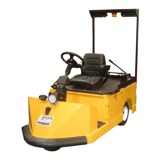
Page 18: Vehicle Controls
TT-316-07 Vehicle Controls 1: Start Switch 3: System Status Indicator Gauge The Start switch turns the vehicle electrical Detailed description of operation can be found control system ON. This switch may or may later in this section. not require a key to operate. Rotate the switch clockwise to turn the vehicle system “ON”... -
Page 19: Steering
TT-316-07 Steering To turn right, turn the steering wheel clockwise. To turn left, turn the steering wheel counter- clockwise. The steering column has both tilt and telescoping features. • Tilt: To tilt the steering up or down, loosen the locking lever, position the steering wheel as required and then retighten the lever. -
Page 20: Inching
TT-316-07 WARNING Inching The inching switches are optional. The inching buttons are located on the left side of Do not attempt to connect or disconnect a the cargo area. The inching buttons will move the trailer while parked on a grade. This may vehicle a short distance at a slow speed to facilitate result in the trailer uncontrolled travel connecting or disconnecting the trailer tongue. - Page 21 TT-316-07 System Status Indicator The Smart View Display (SVD) functions as a Battery Status Indicator (BSI), Hour Meter (HM), speed controller status monitor, and as an optional maintenance monitor feature. The operation of each of these functions is described below and continued on the following page. BSI: A bar graph representing the current state of The Hour Meter has three functions: Key Hours,...
- Page 22 TT-316-07 Maintenance Monitor: Note: The Maintenance Monitor function is optional. The Maintenance Monitor function can be turned ON or OFF by your dealer. Operation: The SVD notifies the operator 10 hours (standard) before a scheduled maintenance is due. During this warning period, the meter will continue to alert the operator. This should allow sufficient time for the operator to schedule the maintenance that is due, with minimal down time.
- Page 23 TT-316-07 Flash Message Action F22001 Seat Fault Operator presence switch is open. Confirm driver seat properly positioned. F22002 Two Direction Fault Refer to dealer for repair. F22003 SRO Fault Throttle pedal pressed without direction selected. F22004 Sequence Fault Throttle or direction selected at power up. F22006 Inch Fault Inching switch active along with any drive...
-
Page 24: Vehicle Operation
TT-316-07 Vehicle Operation General Safety Guidelines WARNING Your ability to operate a motor vehicle can be seriously impaired with blood alcohol levels far below the legal minimum. If you have been drinking alcohol, don’t drive. Ride with a designated non-drinking driver, call a cab, or use public transportation. WARNING The advanced technology built into the vehicle motor control has many systems to monitor the condition and operation of the vehicle to maintain safe operation. - Page 25 TT-316-07 • This vehicle may overturn if turned sharply when driven at high speeds. • Drive slowly when making a turn, especially if the ground is wet or when driving on an incline. • Yield right of way to pedestrians, ambulances, fire trucks, or other emergency vehicles. •...
-
Page 26: Starting
TT-316-07 Starting Before operating this vehicle: Refer to General Safety Guidelines at the beginning of this chapter. WARNING The seat interlock switch is only one part of the vehicle safety system. The interlock switch should not be relied upon as the only safety feature used to disable or disengage this vehicle. -
Page 27: Driving
TT-316-07 Driving Before operating this vehicle: • Perform all daily and pre-operation checks as defined in the Vehicle Maintenance section. • Refer to General Safety Guidelines at the beginning of this section. WARNING DO NOT exceed the maximum rated speed for your vehicle, locally imposed speed limits, or the safe operating speed for conditions. -
Page 28: Material Handling Safety Light
TT-316-07 Stopping Release the throttle pedal and use your right foot to press the brake pedal. The amount of force required to stop the vehicle will vary depending on the environment and load on the vehicle. Unless in an emergency, do not turn the start witch OFF until the vehicle has come to a complete stop. -
Page 29: Collisions Or Accidents
TT-316-07 Collisions or Accidents A collision or accident may damage the electrical circuits or batteries resulting in a fire hazard or chemical spill. In the event of a collision or accident, immediately turn the Start switch OFF, set the park brake, then exit the vehicle. Call emergency personnel if there is any indication of smoke, burning smell, electrical arcing, or leaking fluid. -
Page 30: Loading Cargo
• The standard designated cargo area is the rear deck. Only load cargo on the deck unless the vehicle has been equipped with Taylor-Dunn approved alternative cargo storage areas. Make sure cargo loaded on the deck does not interfere with the operation of the manual hitch release lever. -
Page 31: Transporting Pets
• Do not exceed the load capacity of the trailer. • Do not exceed the capacity of the trailer hitch. • Only use Taylor-Dunn approved trailer hitches. • Cargo consisting of fluid in tanks shall have fluid baffles in the tank to help reduce shifting load weight. -
Page 32: Towing The Vehicle
TT-316-07 Towing the Vehicle Note: This vehicle is equipped with an automatic electric park brake. The brake must be bypassed or removed before towing the vehicle. Note: If at all possible, this vehicle should be placed on a carrier, rather than towing. WARNING DO NOT tow a vehicle with a tow strap if the vehicle brakes are not working properly. -
Page 33: Charging Your Vehicle
TT-316-07 Charging Your Vehicle GENERIC SAFETY GUIDELINES DANGER The charger must be connected to a properly grounded AC receptacle. Improper connection will increase the risk of electric shock and can cause severe personal injury or death. WARNING • Explosive mixtures of Hydrogen gas are present within battery cells at all times. Do not work with or charge a battery in an area where open flames (including gas furnace or water heater pilots), sparks, cigarettes, or any other sources of combustion are present. -
Page 34: Charging Time
The United States Federal, State or local regulations may require the use of a Ground Fault Interrupter (GFI) cable or AC outlet equipped with a GFI for charging your vehicle. A charger cord with an integral GFI is available through your Taylor-Dunn dealer. Page 34... -
Page 35: Storing And Returning To Service
TT-316-07 Storing and Returning to Service Both storing your vehicle and returning it to service should only be performed by authorized personnel. NOTICE Storing Your Vehicle • Clean the batteries, then fill and charge before Storing batteries that are putting the vehicle in storage. Do not store batteries discharged or allowing stored in a discharged condition. -
Page 36: Vehicle Maintenance
TT-316-07 Vehicle Maintenance Daily Inspection The following items should be inspected once every day before the vehicle is put into service: • External frame damage (body). • Operation of all lights and warning alarms or beepers. • Inspect for leaking fluids or grease. •... -
Page 37: Interlock Switch Inspection
TT-316-07 INTERLOCK SWITCH INSPECTION The interlock switches should disable vehicle operation when activated. Perform the following to confirm proper operation. If any one test fails, then immediately remove the vehicle from service and refer repair to a qualified technician. WARNING These procedures may result in unexpected vehicle movement. -
Page 38: Battery Door Switch
TT-316-07 Battery Door Switch Remove all battery access doors. Sit in the operator position, turn the start switch ON, select a direction, and slowly press the throttle pedal. • The vehicle should not operate. Replace one door at a time and attempt to operate the vehicle after each door is installed. •... -
Page 39: Maintenance Schedule
TT-316-07 Maintenance Schedule Most of these items should only be performed by a qualified technician. Details regarding the service procedures can be found in the vehicle service manual. Any problems found during an inspection should be repaired before the vehicle is put back into service. -
Page 40: Battery Maintenance
TT-316-07 BATTERY MAINTENANCE WARNING High Voltage is present in the battery compartment. DO NOT touch the battery terminals during servicing of the battery as this may result in severe electric shock and/or death. DANGER • Battery electrolyte is poisonous and corrosive. It contains sulfuric acid. Avoid contact with skin, eyes, or clothing. -
Page 41: Cleaning
TT-316-07 Cleaning WARNING 1) Refer to battery warnings at the start of this chapter. 2) Place the Direction Control switch in the center “OFF” position (neutral). 3) Turn the Start switch OFF. 4) Place blocks under the front or rear wheels to prevent vehicle movement. 5) Disconnect the main battery plug. -
Page 42: Removable Batteries
TT-316-07 REMOVABLE BATTERIES Removable batteries can consist of a single large industrial battery or a pack of smaller batteries assembled on a removable tray. The removable battery can be of a type that slides or rolls out of the side of the vehicle (ROBB) or lifted out of the vehicle from above (LOBB). -
Page 43: Side Extract Battery
TT-316-07 Side Extract Battery 1. Position the vehicle as close as possible to the platform or dolly where the battery is to be extracted. 2. Turn the start switch OFF and set the park brake. 3. Disconnect the battery cable connector. 4. -
Page 44: Tires
TT-316-07 TIRES WARNING Incorrect tire inflation can result in sudden failure of the tire and/or braking / steering problems leading to loss of control of the vehicle. Never exceed the maximum pressure as indicated on the side wall of the tire. Exceeding the maximum pressure may cause explosive failure of the tire resulting in severe bodily injury. -
Page 45: Tire Tread Wear
TT-316-07 Tire Tread Wear WARNING DO NOT operate a vehicle if the cord is visible on any tire (see illustration). A tire in this condition may suddenly fail at any time resulting in loss of control of the vehicle. It is important to periodically inspect the tread on each tire for wear. Driving with inadequate tread increases the risk of losing control of the vehicle due to hydroplaning on a wet road surface. -
Page 46: Tire Rotation
Never mix tire types, tire sizes, speed ratings, or load capacity. Only use the tire types and sizes approved for use on this model. Contact your authorized Taylor-Dunn dealer to confirm approved tire types and sizes. Mixing tires or installing a tire that is not approved may: •... -
Page 47: Brake Fluid Level
TT-316-07 BRAKE FLUID LEVEL WARNING • Only use DOT 3 brake fluid from a new sealed container. • DOT 3 brake fluid is corrosive and will damage paint finishes. • Dispose of brake fluid in accordance with local state and federal regulations. •... -
Page 48: Cleaning
TT-316-07 CLEANING Batteries Refer to the Battery Maintenance section. Seats Control Panel Clean your seats with any standard automotive vinyl cleaner. DANGER Interior High Voltage is present in the control Use a mild liquid detergent in warm water to wipe panel. -
Page 49: Standard Specifications
TT-316-07 Standard Specifications ITEM SPECIFICATION Occupancy 1 Driver, No Passengers Dimensions 80.5 L x 36.5 W x ? 46.25 H Inches Height does not include light bar 204.4 L x 100.3 W x 117.4 H cm Turning Radius 70.5 Inches (179 Centimeters) Weight (without batteries) 1,150 pounds (520 kg) Battery... -
Page 50: Index
Exterior Body Interior Parking Collisions Parking Brake Warning icons Bypass Switch 19, 32 Web Site Pets Web site, Taylor-Dunn Daily Inspection Pets, Transporting Data plate Pre-Operation Inspection Dealer List Decals Direction Control Switch Returning to Service Direction of travel Draw Bar Pull... - Page 51 TT-316-07 TT-316 Curtis AC System Operator Manual Page 51...
- Page 52 For more information go to www.P65Warnings.ca.gov/passenger- vehicle. Taylor-Dunn Mfg. ® 2114 W. Ball Rd. Anaheim, CA 92804 (800)-688-8680 (714) 956-4040 (FAX) (714) 956-0504 Visit our Web site: www.taylor-dunn.com Page 52 TT-316 Curtis AC System Operator Manual...
Need help?
Do you have a question about the TT-316 36AC and is the answer not in the manual?
Questions and answers
Can you give me the battery box specs of the Taylor Dunn TT316 model?
The battery box specifications for the Taylor-Dunn TT-316 36AC model are:
- Dimensions: 38W x 16L x 15H inches (96 x 40 x 38 cm)
- Lead position: A
- Lead length: 30 inches (76 cm)
- No cover
- Connector: SB350 gray
This answer is automatically generated