Page 1
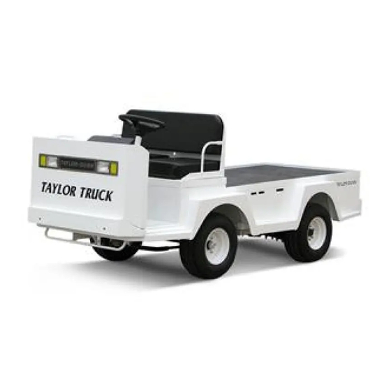
Taylor Truck ET 3000 Models Inlcuded: B0-T48-48 Taylor Truck (T48) ET-030-48 (ET 3000) T h e B e s t W a y T o G o A b o u t Y o u r B u s i n e s s...
Page 3
Taylor-Dunn has a network of dealers distributed around the globe to support our vehicles. Information regarding vehicle sales, replacement parts, or service should be obtained through your local dealer. A dealer locator can be found on the Taylor-Dunn website at www.taylor-dunn.com.
Page 4
B2-10 Ambulance B2-48 With Dump Bed Option B2-48 with Steel Cab, Foldaway 4-Passenger Seat and Stake Sides ET 3000 P2-50 30,000 Pound Tow Tractor ET1-50 Full Size Truck...
Page 5
Section Index Taylor-Dunn ® Operator and Service Manual Section Index Introduction Safety Rules and Operating Instructions General Maintenance Front Axle Service Steering Component Service Brakes Service Throttle Linkage Transaxle Service Suspension Motor Service Tires and Wheels Battery Service Control System Troubleshooting...
Page 6
A small sample of the many types of vehicles offered by Taylor-Dunn ® B 2-48-36 Equipped with optional B 1-00 Personnel carrier hydraulic dump bed BT 2-80 Eight passenger tram MX 1600 Equipped with optional ladder rack and weld tanks...
Table of Contents About this manual ......... 2 Who Should Read This Manual ....2 Responsibilities ..........2 How To Use This Manual ......3 Conventions .............. 3 How to Identify Your Vehicle ......4 Taking Delivery of Your Vehicle ....5 Shown with fiberglass steel cab options Shown with extended steel cab...
The purchase of this vehicle shows a belief in high Of the Owner... quality products manufactured in the USA. ® ® The owner of this or any Taylor-Dunn vehicle is Taylor-Dunn , a leading manufacturer of electric responsible for the overall maintenance and repairs burden and personnel carriers since 1949, wants to of the vehicle, as well as the training of operators.
INTRODUCTION HOW TO USE THIS MANUAL Conventions This manual is organized into five main sections: Symbols and/or words that are used to define warnings, cautions, instructions, or notes found INTRODUCTION throughout this manual. Refer to the examples below. This section describes how to use this service manual and how to identify your vehicle.
INTRODUCTION HOW TO IDENTIFY YOUR VEHICLE This manual applies to vehicles with the same model and serial numbers listed on the front cover. These vehicles are designed for driving on smooth surfaces in and around facilities such as industrial plants, nurseries, institutions, motels, mobile home parks, and resorts.
The only personnel authorized to repair, modify, or • Check that all wire connections, battery adjust any part of this or any Taylor-Dunn ® vehicle is cables, and other electrical connections are a factory authorized service technician.
Page 13
Signet Charger Operation, Model HB Series ..12 Signet Charger Operation, Model HBS series ..13 Lestronic II Charger Operation ......14 Taylor-Dunn X-Series Charger ......15 Charging with the X-Series Charger ..... 16 AC Power Source ..........17 New Battery Break in ........... 17 Charging Time ............
SAFETY RULES AND OPERATING INSTRUCTIONS STANDARD SPECIFICATIONS* ITEM SPECIFICATION Occupancy Driver, one passenger Dimensions Taylor Truck 318 L x 127 W x 119 H Centimeters 125 L x 50 x 47H Inches ET 3000 325 L x 127 W x 119 H Centimeters 128 L x 50 x 47H Inches Turning Radius 368 Centimeters (145 Inches)
SAFETY RULES AND OPERATING INSTRUCTIONS SAFETY RULES AND DRIVER TRAINING PROGRAM GUIDELINES According to ANSI B56.8, the owner of this vehicle shall conduct an Operator Training program for all those who It is the responsibility of the owner of this vehicle to assure will be operating this vehicle.
SAFETY RULES AND OPERATING INSTRUCTIONS VEHICLE CONTROLS DASH (UP TO S/N 179999) 1) Key-Switch A key-switch, located on the right center side of the instrument panel, turns on the vehicle. Rotate the key clockwise to turn the vehicle power on, counterclockwise to turn the vehicle power off.
SAFETY RULES AND OPERATING INSTRUCTIONS DASH (STARTING S/N 180000) 1) Headlight Switch The headlight switch is located on the left sideof the instrument panel. Push the top of the switch to turn the 5) Hi-Low Switch (optional) lights on. Push the bottom of the switch to turn the lights The high-low switch will be switch #5 or #7 depending on off.
SAFETY RULES AND OPERATING INSTRUCTIONS Steering The steering wheel and steering system are similar to an automobile. To turn right, turn the steering wheel clockwise. To turn left, turn the steering wheel counter-clockwise. If equipped with tilt steering, the release lever is located on the lower left of the steering column.
SAFETY RULES AND OPERATING INSTRUCTIONS Directional Signals (Optional) The turn signal lever is located on the left side of the steering column. Push the lever forward to activate the right turn signal and pull the lever back to activate the left turn signal. Hazard Light Switch (Optional) The hazard light switch is located on the left side of the steering column.
SAFETY RULES AND OPERATING INSTRUCTIONS Smart View Display The Smart View Display (SVD) functions as a Battery Status Indicator (BSI), Hour Meter (HM), speed controller status monitor, and as an optional maintenance monitor feature. The operation of each of these functions is listed below.
Page 21
SAFETY RULES AND OPERATING INSTRUCTIONS Speed controller status: The display will indicate a fault code whenever the control system logic detects a problem with the control system. A fault code is being displayed whenever the Fault Code Indicator (the letter ‘F’) is visible at the left of the numeric display.
SAFETY RULES AND OPERATING INSTRUCTIONS While driving: VEHICLE OPERATIONAL • Slow down and sound the horn to warn pedestrians GUIDELINES or when approaching a corner or other intersection. • No reckless driving. Safety Guidelines • Do not drive this vehicle on steep inclines or where •...
SAFETY RULES AND OPERATING INSTRUCTIONS Parking Towing This Vehicle Before leaving the vehicle: • Set the parking brake. This vehicle is equipped with regenerative • Set the forward-off-reverse switch to the ` “OFF” braking. Follow these steps before towing position. this vehicle.
SAFETY RULES AND OPERATING INSTRUCTIONS CHARGING YOUR VEHICLE WARNING CAUTION Explosive mixtures of Hydrogen gas are present The key switch must be in the “OFF” position within battery cells at all times. Do not work when charging the batteries. Failure to turn the with or charge a battery in an area where open key switch “OFF”...
SAFETY RULES AND OPERATING INSTRUCTIONS WARNING CAUTION Explosive mixtures of Hydrogen gas are present The key switch must be in the “OFF” position within battery cells at all times. Do not work when charging the batteries. Failure to turn the with or charge a battery in an area where open key switch “OFF”...
Always provide ample ventilation in rooms where batteries are Taylor-Dunn X-Series Charger being charged. Failure to do so may result in severe bodily injury and/or property damage. This charger is rated for 115 VAC or 230 VAC operation (nominal).
SAFETY RULES AND OPERATING INSTRUCTIONS Self Diagnosis Procedure If you suspect a battery charging problem press the self diagnostic switch to start the charger self diagnostic procedure. Any faults found by the procedure will be displayed by the two LED’s. Refer to the table below for the fault codes. Note: To run this procedure, a battery that is not severely discharged must be connected to the charger.
SAFETY RULES AND OPERATING INSTRUCTIONS AC Power Source Charging Time WARNING The AC power source Average charging time is 8 to 10-hours. The time required Use of extension cords required by the charger will to fully charge your batteries will vary depending on: is not recommended.
SAFETY RULES AND OPERATING INSTRUCTIONS PERIODIC MAINTENANCE CHECKLIST Safety Rules NOTE: A full page copy of the Periodic Maintenance Checklist is on Page 18 the Vehicle Documentation CD under the [Misc] sub folder.
SAFETY RULES AND OPERATING INSTRUCTIONS STANDARD PERIODIC MAINTENANCE SCHEDULE FOR THE SMART VIEW DISPLAY NOTE: The maintenance function is optional. Your vehicle may be equipped with a customized maintenance schedule PREVENTATIVE MAINTENANCE SCHEDULE MAINTENANCE HOUR MAINTENANCE TO BE PERFORMED LEVEL INTERVAL Inspect the brake system including the park brake and mounting harware...
SAFETY RULES AND OPERATING INSTRUCTIONS Daily Visual inspection: Tire condition and pressure. External frame damage (body). Operation of all lights and warning alarms and/or horns. Smooth and proper operation of all controls such as but not limited to: • Accelerator pedal, Brake pedal, Steering, Parking brake, etc. •...
Page 33
Table of Contents Maintenance Guidelines ....... 2 Troubleshooting Guide ........ 3 Lubrication Chart .......... 4 Model C 4-25 Tow Tractor Examples of Taylor-Dunn Tow Tractors Model E 4-55 Tow Tractor...
Page 34
• Inspect and maintain battery limit switches, protective devices, electrical conductors, and connections in ® conformance with Taylor-Dunn’s recommended procedures. • Keep the vehicle in clean condition to minimize fire hazards and facilitate detection of loose or defective parts.
Page 35
Maintenance, Service and Repair Troubleshooting Guide Symptom Probable Cause Front End Out of Alignment Steering Pulls in One Direction Low Tire Pressure Dry Lube Points in Steering Linkage Hard Steering Damaged King Pin/Ball Joint Low Tire Pressure Worn Ball Joints Excessive Steering Play Mis-Adjusted or Worn Steering Gear Loose Steering Linkage...
Maintenance, Service and Repair Lubrication Chart Description Locations Lubricant Type Ball Joints General Purpose Grease Pedal Linkages General Purpose Grease Front Wheel Bearings High Temperature Wheel Bearing Grease King Pin General Purpose Grease Drive Drain Plug Drive Level Plug Fill Plug SAE 80w90 hypoid Gear Oil Page 4...
Page 37
TABLE OF CONTENTS Inspect the Front Wheel Bearings and King Pin........2 Adjust Front Wheel Bearings .... 3 Front Axle Removal and Installation .. 4 Removal ..............4 Installation ............4 Front Axle Disassembly ..... 5 Replace Front Wheel Bearings ..6 Replace the King Pins and Bushings .
Maintenance, Service, and Repair INSPECT THE FRONT WHEEL BEARINGS AND KING PIN 1. Make sure the key-switch is in the “OFF” position, then remove the key. 2. Place the forward-reverse switch in the center “OFF” position. 3. Confirm the electric park brake is set. 4.
Maintenance, Service, and Repair ADJUST FRONT WHEEL BEARINGS 1. Make sure the key-switch is in the “OFF” position, then remove the key. 2. Place the forward-reverse switch in the center “OFF” position. 3. Confirm the electric park brake is set. 4.
Maintenance, Service, and Repair Installation FRONT AXLE REMOVAL AND INSTALLATION 1. Make sure the key-switch is in the “OFF” position, then remove the key. Removal 2. Place the forward-reverse switch in the center “OFF” position. 3. Confirm the electric park brake is set. 1.
Maintenance, Service, and Repair FRONT AXLE DISASSEMBLY Disassembling and reassembling involves removing and replacing the left and right steering knuckles and king pin bushings. Refer to the following sections for information regarding these procedures: Replace the Steering Knuckle Replace the King Pins and Bushings Front Axle NOTE: The front axle does not have to be removed unless the axle beam must be replaced.
Maintenance, Service, and Repair 12. Assemble in reverse order, using new grease REPLACE FRONT WHEEL seals. BEARINGS NOTE: Refer to Adjust Wheel Bearings for information regarding proper tightening of the spindle nut 13. Install the hub dust cap. 1. Make sure the key-switch is in the “OFF” 14.
Maintenance, Service, and Repair REPLACE THE KING PINS AND BUSHINGS Failure to correctly broach or ream bronze bushings may result in steering difficulty There are different types of king pin bushings depending and loss of control of the vehicle causing on the configuration of your vehicle.
Maintenance, Service, and Repair NOTE: Both the left and right side bushings and thrust REPLACE THE STEERING bearings should be replaced as a set. KNUCKLE 13. Assemble in reverse order. Refer to the illustratinon below for orientation of the thrust bearing.
Page 45
TABLE OF CONTENTS Front End Alignment ......2 Inspect Ball Joints ......5 Inspect Rod Ends ......5 Adjust the Steering Gear ....6 Replace the Steering Shaft ....7 Replace the Steering Wheel ....8 Replace the Steering Gear ....8 Replace the Ball Joints, Tie Rods, and Drag Link ..........
Maintenance, Service, and Repair FRONT END ALIGNMENT This section will refer to two different types of ball joints. One type is has a grease fitting and a tapered shaft where it is fitted to the steering arm or pitman arm. The second type cannot be greased and has a straight shaft.
Page 47
Maintenance, Service, and Repair 12. Adjust the drag link so that it can be easily inserted into the pitman arm. 13. Tighten the ball joint or rod end nut as specified below: Ball joint - 40-45 ft-lbs. Rod end - 20-25 ft-lbs. 14.
Page 48
Maintenance, Service, and Repair Front wheel alignment NOTE: It is recommended to center the steering before aligning the front wheels. Refer to the Center the Steering section for information. 1. Make sure the key-switch is in the “OFF” position, then remove the key. 2.
Maintenance, Service, and Repair INSPECT BALL JOINTS INSPECT ROD ENDS NOTE: A set of ball joints and/or rod ends will wear NOTE: A set of ball joints and/or rod ends will wear at the same rate. If a ball joint and or rod end at the same rate.
Maintenance, Service, and Repair ADJUST THE STEERING GEAR NOTE: In some vehicle configurations it may be necessary to remove the steering gear to Replace perform this procedure. Refer to the Steering Gear for information regarding removing the steering gear. 1. Make sure the key-switch is in the “OFF” position, then remove the key.
Maintenance, Service, and Repair REPLACE THE STEERING SHAFT 1. Make sure the key-switch is in the “OFF” position, then remove the key. 2. Place the forward-reverse switch in the center “OFF” position. 3. Confirm the electric park brake is set. 4.
Maintenance, Service, and Repair REPLACE THE STEERING REPLACE THE STEERING WHEEL GEAR 1. Make sure the key-switch is in the “OFF” 1. Make sure the key-switch is in the “OFF” position, then remove the key. position, then remove the key. 2.
Maintenance, Service, and Repair REPLACE THE BALL JOINTS, TIE RODS, AND DRAG LINK This section will refer to two different types of ball joints. One type is has a grease fitting and a tapered shaft where it is installed on the steering arm or pitman arm. The second cannot be greased Rod End and has a straight shaft.
Maintenance, Service, and Repair Replacing a Ball Joint 11. Install the new ball joint into the steering sleeve. Screw it into the sleeve the same number of turns counted in the previous step. Do not tighten the ball joint clamp at this time. 1.
Maintenance, Service, and Repair 9. Install in reverse order. 11. Lower the vehicle. 10. Realign the front wheels. 12. Reconnect the main positive and negative cables at the batteries. Steering NOTE: Refer to the section for information 13. Remove the blocks from behind the wheels. regarding realignment of the front wheels.
Maintenance, Service, and Repair REPAIR THE STEERING GEAR Disassembly NOTE: The steering gear must be removed from the vehicle for this procedure. Refer to Replace the Steering Gear section for information regarding removing the steering gear. NOTE: The steering gear is packed with grease. Only perform maintenance on the steering gear in an area that will contain any grease that may spill out of the steering gear when it is disassembled.
Page 57
Maintenance, Service, and Repair Reassembly 1. Lightly lubricate all parts before reassembly. 2. Install a new worm shaft seal and pitman shaft seal into the housing. 3. Install the upper worm bearing cup. 4. Divide the ball bearing into two equal groups. 5.
Maintenance, Service, and Repair Exploded View of Steering Gear Steering Page 14...
Page 59
TABLE OF CONTENTS Inspect the Service Brake ....2 Disc Brake Pads ............ 2 Disc Brake Rotor ..........2 Inspect the Parking brake ....3 Adjust the Service Brakes ....3 Two or Four Wheel Hydraulic Disc Brakes ..3 Adjust the Parking Brake ....
Disc Brake Pads Disc Brake Rotor NOTE: The front brake rotor is an integral part of the front hub. If the brake rotor is worn beyond Current Taylor-Dunn brakes are asbestos ® its service limits, then the front hub must be free.
Maintenance, Service, and Repair INSPECT THE PARKING ADJUST THE SERVICE BRAKE BRAKES Two or Four Wheel Hydraulic Disc Brakes NOTE: The parking brake is actuated through a pin in the center of the rear left and right brake The hydraulic disc brake system is automatically body on the rear axles.
Maintenance, Service, and Repair ADJUST THE PARKING BRAKE Wheel Park Brake The parking brake is actuated through a pin in the center of the rear left and right brake body on the rear axles. 1. Make sure the key-switch is in the “OFF” position, then remove the key.
Maintenance, Service, and Repair CHECK MASTER CYLINDER FLUID Do not ingest brake fluid or allow contact 1. Make sure the key-switch is in the “OFF” with skin or eyes. Always wear protective position, then remove the key. clothing and a face shield when working 2.
Maintenance, Service, and Repair BLEED THE BRAKE SYSTEM Always use brake fluid from a new sealed NOTE: Start this procedure at the wheel furthest from container. Never reuse any brake fluid that the master cylinder, then work toward the has been removed from the brake system. wheel closest to the master cylinder.
7. If equipped with front brakes, raise the front wheels off of the ground and support with jack stands. 8. Release the park brake. Current Taylor-Dunn brakes are asbestos ® free. However, there is the possibility that 9.
Maintenance, Service, and Repair REPLACE FRONT DISC BRAKE PADS Current Taylor-Dunn brakes are asbestos ® free. However, there is the possibility that NOTE: It is recommended that both the left and right the original brakes were replaced with brake pads be replaced as a set.
Maintenance, Service, and Repair REPLACE REAR BRAKE PADS OR SHOES NOTE: It is recommended that both the left and right Current Taylor-Dunn brakes are asbestos ® brake pads be replaced as a set. free. However, there is the possibility that...
Maintenance, Service, and Repair REPLACE THE WHEEL CYLINDER Current Taylor-Dunn brakes are asbestos ® free. However, there is the possibility that the original brakes were replaced with Disc Brake Body Assembly (front or rear) aftermarket parts containing asbestos. Since this possibility exists, all brake parts should be handled as if they contain asbestos.
Maintenance, Service, and Repair REPAIR THE BRAKE BODY Hydraulic brake system components must be kept clean. Make sure your work area is free from dirt and debris and will contain any brake fluid spills. Any debris or contaminates left in the brake system could lead to brake failure and result in property damage and/or severe bodily injury.
Page 70
Maintenance, Service, and Repair 12. Install the o-rings into the brake body. Make sure that the o-rings are installed into the second groove and that they are not twisted. NOTE: There are two different brake assemblies. One has a standard o-ring with a round cross section, the other has a square cross section.
Maintenance, Service, and Repair REPLACE THE MASTER CYLINDER Do not ingest brake fluid or allow contact with skin or eyes. Always wear protective NOTE: Most vehicle configurations do not require clothing and a face shield when working lifting the vehicle to remove the master with or around brake fluid.
Maintenance, Service, and Repair REPAIR THE MASTER CYLINDER NOTE: Hydraulic brake system components must be kept clean. Make sure your work area is free from dirt and debris and will contain any brake fluid spills. Remove the master cylinder from the vehicle. See Replace the Master Cylinder section . Drain all fluid from the master cylinder and discard.
Page 73
TABLE OF CONTENTS Throttle Linkage Adjustments .... 2 Magnetic Module ..........2 Pot Box module ............ 3...
Page 74
Maintenance, Service, and Repair THROTTLE LINKAGE ADJUSTMENTS Magnetic Module The standard magnitic throttle module should not be used in areas that contain large magnetic fields. Large magnitic fields may effect the operation of the module resulting in unexpected movement of the vehicle. The throttle pedal is attached directly to the throttle module.
Page 75
Maintenance, Service, and Repair Pot Box module The pot box module is used on vehicles that are to be operated in areas with large magnetic fields. The linkage to the pot box should be adjusted so that the FS-1 switch closes just as the pedal is depressed and the output is at 5K with the pedal fully depressed.
Page 77
TABLE OF CONTENTS Check Oil Level ......... 2 Change Oil ..........2 Motor Removal and Installation ....3 Rear Hub or Rotor ........3 Removing and Installing the Rear Axles ..4 Disassembly and Reassembly of the Primary Reduction Gear Case ....6 Disassembling the 3rd Member ....
Maintenance, Service, and Repair CHECK OIL LEVEL CHANGE OIL The oil flows freely between the main gear case (3rd member) and the primary reduction gear case. It is only necessary to check the oil level of the 3rd member. 1. Make sure the key-switch is in the “OFF” Park the vehicle on a level surface.
Maintenance, Service, and Repair REAR HUB OR ROTOR MOTOR REMOVAL AND INSTALLATION NOTE: The torque specification for the axle hub bolt is 275 ft-lbs. An impact wrench will be NOTE: Some applications will require removing the required to remove the bolt. drive assembly from the vehicle to remove NOTE: The axle hub bolt has a special thread locking Removing and...
Maintenance, Service, and Repair REMOVING AND INSTALLING THE REAR AXLES The axle retaining plate bolts have a pre- applied thread locking compound. They are The oil level in the housing is above the bottom of the intended for one time use only. If removed axle flange.
Page 81
Maintenance, Service, and Repair 12. Secure the brake body assembly, do not let it hang by the brake hose. 13. Pull the axle out of the housing. 14. Inspect all bearings for roughness or play, replace as needed. 15. Install in reverse order, lubricate the o-ring. NOTE: Be sure not to damage the o-ring.
Maintenance, Service, and Repair DISASSEMBLY AND REASSEMBLY OF THE Be careful not to damage the sealing surfaces on the housings. Damage to the PRIMARY REDUCTION GEAR sealing surface may lead to an oil leak resulting in damage to the internal parts CASE of the drive.
Page 83
Maintenance, Service, and Repair Lubricate all parts with gear oil before installation. Failure to pre-lube the parts may result in premature failure. 19. Assemble the gear case in reverse order. NOTE: Torque the drain plug to 21-25 foot-pounds. NOTE: Torque the gear case to 3rd member retaining bolts to 18-20 foot-pounds.
Maintenance, Service, and Repair 12. Remove the 12 side DISASSEMBLING THE 3RD plate bolts, then remove the side plate. MEMBER 1. Make sure the key-switch is in the “OFF” position, then remove the key. 2. Place the forward-reverse switch in the 13.
Maintenance, Service, and Repair 17. Remove the carrier ASSEMBLING THE 3RD bearing race from the 3rd member housing. MEMBER 1. Temporarily install the pinion gear (hand tighten only). 2. Install the carrier bearing race ring nuts into the 18. Remove the front housing and cover.
Page 86
Maintenance, Service, and Repair 9. Pre set the carrier 16. Adjust the gear lash if needed by tightening or bearing preload by loosening the carrier bearing race ring nuts. The tightening the housing two ring nuts must be turned equally in opposite carrier bearing race ring directions.
Maintenance, Service, and Repair Pinion Bearing Preload PINION GEAR SHIMMING NOTE: The pinion gear depth must be set before the INSTRUCTIONS Setting the Pinion Gear preload. Refer to Depth NOTE: This procedure is required only when replacing the front or rear pinion bearings and races or 1.
Page 88
Maintenance, Service, and Repair Figreu 1b Figreu 1a Figure 2 Figure 4 NOTE: Values shown are for reference only Figure 3 Transmission Page 12...
Page 89
TABLE OF CONTENTS Replace the Rear Springs ....2 Leaf ............... 2 Replace the Front Springs ....3 Leaf ............... 3 Replace the Spring Bushings ..... 4 Replace the Shocks ......5 Front ..............5...
Maintenance, Service, and Repair 8. Unbolt the spring from the axle housing. REPLACE THE REAR SPRINGS 9. Support the spring so that it cannot fall out of the vehicle. 10. Remove the remaining hardware retaining the Leaf spring to the frame. If a spring has failed or is fatigued, then it is 11.
Maintenance, Service, and Repair REPLACE THE FRONT SPRINGS Damaged or worn spring bolts or hangers could result in sudden failure of the Leaf suspension causing severe bodily injury or If a spring has failed or is fatigued, then it is property damage.
Maintenance, Service, and Repair 7. Remove the spring from the vehicle. REPLACE THE SPRING Replace the Front Springs NOTE: Refer to BUSHINGS section for information regarding removing the front springs. It is recommended that all front spring bushings are 8. If the vehicle is equipped with spring hangers, replaced as a set.
Maintenance, Service, and Repair 7. Remove the upper and lower shock bolts. REPLACE THE SHOCKS 8. Remove the shock from the vehicle. NOTE: If the shock that was removed is to be reinstalled: A. Inspect the shaft where it enters the shock body for any signs of leakage.
Page 95
TABLE OF CONTENTS Inspecting the Motor Brushes .... 2 Motors with internal cooling fans ......2 Enclosed Motors (GE, no cooling fan) ....2 Motor Removal and Installation ..3 Motor Inspection ........ 3 Replacing the Brushes....... 5 Replacing the Bearings ..... 6 Repairing the Commutator ....
Motor Service INSPECTING THE MOTOR BRUSHES Typical brush and brush holder Enclosed Motors (GE, no cooling fan) Typical motor with cooling fan indicated by the arrow Motors with internal cooling fans General Electric Motors NOTE: There are four brushes in the motor. The brushes will not wear at the same rate.
Motor Service Advanced DC Motors Inspection The enclosed Advanced DC motors must be 1. Measure the length of each motor brush. disassembled to inspect the motor brushes. Refer to • If any one brush is less than or equal to the Motor Inspection for information regarding Service...
Page 98
Motor Service 5. Inspect the commutator for burn marks. commutator segments and the armature frame. If it is not an open circuit, then the armature is • Burn marks and/or raised commutator segments shorted and the motor must be replaced. 90 or 180 degrees apart is evidence of a shorted armature.
Motor Service Brush Spring Orientation 3. Install the new brushes in reverse order. REPLACING THE BRUSHES 4. Be certain that the brush springs do not rest up NOTE: It is recommended that all four brushes be against the brush wires. Refer to illustrations in replaced as a set.
Motor Service 6. Measure the commutator undercut depth in 5- REPLACING THE BEARINGS places around the commutator. If any one of the measurements is less than the minimum undercut 1. The motor must be removed from the vehicle for Service Limits depth specified in , then the this procedure.
Maintenance, Service, and Repair TIRE INFLATION TIRE INSPECTION 6. Check the tire pressure. Refer to Tire Inflation section for information on checking the tire pressure. 1. Make sure the key-switch is in the “OFF” 7. Inspect the tire tread depth. Minimum position, then remove the key.
Maintenance, Service, and Repair REPLACE THE TIRE/WHEEL REPLACE THE TIRE (PNEUMATIC) NOTE; To replace the tire, the tire/wheel assembly 1. Make sure the key-switch is in the “OFF” must be removed from the vehicle. Refer to position, then remove the key. Replace the Tire/Wheel section for information on removing the tire/wheel...
Maintenance, Service, and Repair 4-Bolt Pattern 5-Bolt Pattern 8-Bolt Pattern Pattern for tightening the wheel nuts Re-torque all wheel nuts to their final value after 1-week (20-hours) of operation. Failure to re-torque the wheel nuts may result in the wheel coming off of the vehicle causing severe bodily injury and/or property damage.
Page 107
TABLE OF CONTENTS Cleaning ..........2 Testing ..........3 Charging ........... 4 Watering ........... 5 Replacing (6-volt batteries only) ..6 Moist Charge Batteries ......... 7 Storage and Returning to Service ..8 Storage ..............8 Returning to Service ..........9...
Maintenance, Service, and Repair CLEANING Explosive mixtures of Hydrogen gas are 1. Make sure the key-switch is in the “OFF” present within battery cells at all times. Do position, then remove the key. not work with or charge battery in an area 2.
Maintenance, Service, and Repair TESTING Explosive mixtures of Hydrogen gas are 1. Make sure the key-switch is in the “OFF” present within battery cells at all times. Do position, then remove the key. not work with or charge battery in an area 2.
Maintenance, Service, and Repair Cleaning the Batteries Clean the batteries. Refer to section for information on cleaning the batteries. Using part number 77-200-00 hydrometer, check and record the specific gravity of each cell in the battery pack. If, after charging, none of the cells exceed a hydrometer reading of 1250 then there may be a fault in the charging system.
Maintenance, Service, and Repair WATERING Explosive mixtures of Hydrogen gas are 1. Make sure the key-switch is in the “OFF” present within battery cells at all times. Do position, then remove the key. not work with or charge battery in an area 2.
Maintenance, Service, and Repair REPLACING (6-VOLT BATTERIES ONLY) NOTE: If the batteries are over one year old, it is recommended to replace them as a set. Explosive mixtures of Hydrogen gas are present within battery cells at all times. Do not work with or charge battery in an area 1.
Maintenance, Service, and Repair 15. Install the batteries in reverse order. Refer to the Illustrated Parts List for battery cable routing. Battery electrolyte is poisonous and 16. It is recommended to replace the battery terminal dangerous. It contains sulfuric acid. Avoid hardware when replacing the batteries.
Maintenance, Service, and Repair STORAGE AND RETURNING TO SERVICE Explosive mixtures of Hydrogen gas are 1. Make sure the key-switch is in the “OFF” present within battery cells at all times. Do position, then remove the key. not work with or charge battery in an area 2.
Maintenance, Service, and Repair Returning to Service 1. Make sure the key-switch is in the “OFF” position, then remove the key. 2. Place the forward-reverse switch in the center “OFF” position. 3. Set the park brake. 4. Place blocks under the front wheels to prevent vehicle movement.
Page 117
Sevcon Control System Troubleshooting Includes Power Pak and Micro Pak controllers TABLE OF CONTENTS Test Equipment Required:....... 2 Definitions: ..........2 Terminology used: ........2 Important Notes and Instructions ... 2 Identifying Your Controller ..... 3 Start Troubleshooting Here ..... 4 Test 8.
• Digital multimeter (DMM) with diode test • This troubleshooting procedure is for the function, FLUKE 79 model shown. Sevcon Power Pak and Micro Pak motor • Throttle Module Analyzer, Taylor-Dunn part speed controllers as equipped in standard number 62-027-32 vehicles. Troubleshooting may not be valid for vehicles equipped with special order speed control options.
Electrical Troubleshooting START TROUBLESHOOTING HERE If your vehicles is equipped with an electric motor brake, the motor brake system must be checked to be sure it is working properly before continuing with this troubleshooting. Operating the speed control when the motor brake has not disengaged may result in damage to Test 9: Electric Motor the motor or speed control system.
Page 121
Electrical Troubleshooting Test 1. CHECKING THE CONTROL LOGIC TEST 1.3: INPUTS Test the voltage at pin #6 on the 12-pin logic card connector. Close the seat switch. Place the high/low switch in the HIGH position. If the voltage is low, then skip ahead to Test #1.4.
Page 122
Electrical Troubleshooting TEST 1.5: Test the voltage at pin #4 on the 12-pin logic card connector. If the voltage is high, then skip ahead to Test #1.6. If the voltage is low, then skip ahead to Test TEST 1.6: Test the voltage at pin #7 on the 12-pin logic card connector.
Page 123
Electrical Troubleshooting Test 2. TESTING THE MOTOR 1. Make sure the key-switch is in the “OFF” position, then remove the key. 2. Place the forward-reverse switch in the center “OFF” position. 3. Set the park brake. 4. Place blocks under the front wheels to prevent vehicle movement. Disconnect both of the battery leads during any maintenance or before disconnecting any electrical component or wire.
Page 124
Electrical Troubleshooting TEST 2.3: Test the continuity from the motor A1 terminal to the frame on the motor and from F1 to A1 for open circuits. Any reading other than an open circuit indicate a short in the motor. If there is a short in the motor, stop here and repair or replace the motor.
Page 125
Electrical Troubleshooting Test 3. THE VEHICLE RUNS IN ONE DIRECTION ONLY Test 3.1: TEST 3.5 Close the seat switch, turn the key switch ON and Disconnect the batteries and remove wires from wait 1-second until the Isolator contactor closes. the B-, F1, and F2 terminals on the controller. If the vehicle runs in reverse only then skip Using the diode test function on your meter, connect ahead to test #3.3.
Page 126
Electrical Troubleshooting Test 4. KEY FAULT TEST 4.1: TEST 4.3: Turn the key switch ON and place the forward and Test the voltage at the cold side (violet/black wire) reverse switch in the center OFF position of the key switch. If the voltage equals battery volts, then skip Perform the following tests: ahead to test #4.4.
Page 127
Electrical Troubleshooting Test 5. CONTACTOR COIL FAULT Disconnect the 12-pin logic card connector from the Sevcon power unit. Turn the key switch ON and perform the following tests: TEST 5.1: Check the voltage on the positive coil terminal of the ISO solenoid (violet wire).
Page 128
Electrical Troubleshooting Test 6. ACCELERATOR MODULE FAULT 1. Make sure the key-switch is in the “OFF” position, then remove the key. 2. Place the forward-reverse switch in the center “OFF” position. 3. Set the park brake. 4. Place blocks under the front wheels to prevent vehicle movement. Disconnect both of the battery leads during any maintenance or before disconnecting any electrical component or wire.
Page 129
Electrical Troubleshooting Test 7. FORWARD AND REVERSE SWITCH FAULT Turn the key switch ON, place the forward and reverse switch in the center OFF position and perform the following tests: TEST 7.1: Referencing battery positive, test the voltage on the center terminal of the F&R switch (Black wire).
Page 130
Electrical Troubleshooting TEST 7.3: If the vehicle does not travel in forward, skip ahead to test #7.4. Place the forward and reverse switch in the REVERSE position. Referencing battery positive, test the voltage at the White/Black wire on the F&R switch. If the voltage equals battery volts, skip ahead to test #7.4.
Electrical Troubleshooting Test 8. ANTI-ROLLOFF FAULT The Sevcon Controller is equipped with a feature called Anti-Rolloff. Anti-Rolloff will automatically slow the vehicle if it starts to roll. Anti-Rolloff is active when the key switch has been left in the “ON” position and the accelerator pedal is not depressed. Anti-Rolloff is deactivated when the key switch is in the “OFF”...
Electrical Troubleshooting Test 9. ELECTRIC MOTOR BRAKE Description: The electric motor brake is a 24-volt electromagnetic disc brake mounted between the drive motor and the primary reduction gear case. The brake is controlled by the speed controller logic. At what times the brake is applied or released is dependent on the controller programing and will vary depending on the model vehicle.
Page 133
Electrical Troubleshooting Connect a volt meter across the Violet/Black wire at the electric brake harness plug and Pin #9 at the logic card connector. The voltage should start at approximately 24 volts, then drop to approximately 15 volts after about 0.5 seconds. If the test is good then: •...
Electrical Troubleshooting Logic Voltage Reference Table Pin # Condition Volts* Key switch off 0 Volts Key switch on Battery Volts F&R in forward F&R in neutral High F&R in reverse High F&R in reverse F&R in neutral High F&R in forward High Accelerator pedal up High...
Electrical Troubleshooting Status LED Code Table The status LED on the Sevcon power unit logic card can be used to give you an idea of where the problem may be. It is recommended that you complete the troubleshooting procedure to confirm failure of any component.
Electrical Troubleshooting Smart View Fault Codes Level 5 Faults (F05xxx) Level 4 Faults (F04xxx) F05000 “Contactor Over Current” F04001: “Contactor Welded” High voltage at power up to the controller B+ terminal. This faut occurs when too much current is going into Check wiring, contactor, and pre-charge resistor on the the line contactor coil circuit.
Page 137
Electrical Troubleshooting Level 2 Faults (F02xxx) Level 1 Faults (F01xxx) F02000: “Accelerator” Most Level 1 faults are a result of operator error or Wiring to throttle module is open or faulty throttle operation of the vehicle. module. F01000: “Power Steer Overheat” F02001: “Accelerator (power up)”...
Page 139
Chapter - TABLE OF CONTENTS Glossary: ............1 Glossary: Lester X-Series Charger ....2 Test Equipment Required for Troubleshooting . 2 Important Notes and Instructions ...... 2 FLA: “Flooded Lead Acid” A battery using plates Theory of Operation .......... 2 made of lead immersed in an acid electrolyte.
Battery Charger LESTER X-SERIES CHARGER SLA batteries must be charged with a charger configured for SLA batteries. Use of any other charger will result in damage to the batteries and premature failure of the batteries. Test Equipment Required for Troubleshooting •...
Battery Charger Fault and Diagnostic Error Code Table Fault Chart B = Blinking, S = Solid, O = Off LED 4 LED 2 Fault Battery voltage out of range or battery capacity is too high Control Board faulty Current Sensor faulty AC voltage incorrect DC current out of range Internal jumper missing...
Battery Charger Testing the Charging Cycle Before starting this procedure: • Confirm that the battery voltage is Charge Profile Wet /FLA AGM / SLA above 1.7 x Number of Cells (36 Constant Current–Voltage Constant Current– Charge Profile Type volts = 18 cells = 1.7 x 18 = 30.6 Slope–Constant Current Constant Voltage volts).
Battery Charger TROUBLESHOOTING SCR Assembly Note: Both SCR’s must be replaced as a set. Note: This test passes current through the transformer and fuse. Confirm both the transformer and fuse are good before continuing. Test: Tools required for this test: Perform the test setup before starting this procedure.
Battery Charger Transformer Lock Out Relay Before continuing, Refer to Testing the Interlock Relay procedure in this section. This is an external test to confirm if While connected to an AC outlet, the charger cabinet the relay is functioning properly. must remain electrically grounded.
Battery Charger Relay Board Assembly Control Board Assembly There is no test for the control board assembly. This test proceedure was not available at the time of printing. Test all other components and confirm all wiring is OK. If all components test good, then it is likely that the control board has failed.
The type of charger is indicated on the charger specification plate on the charger cover. If the charger type is changed, then the Note: The Taylor-Dunn AGM charging profile has been optimized for Full River ® VRLA AGM DC Series batteries.
Battery Charger SIGNET HBS CHARGER SLA batteries must be charged with a charger configured for SLA batteries. Use of any other charger will result in damage to the batteries and premature failure of the batteries. Test Equipment Required for Troubleshooting •...
Battery Charger Operating Instructions and Theory of Operation Typical specification plate (reference only, specifications will vary for different chargers) ® ® The model HBS 600W and HBS 1000W chargers are designed as automatic chargers. The charger turns itself on when it is plugged into the wall outlet and turns off when the batteries are fully charged.
Battery Charger Testing the Charging Cycle In typical installations, The charge cycle will be completed in 8 to 12 hours depending on the state of charge of the batteries when the charge cycle was started. NOTE: The charge cycle time is limited to 20-hours (max). A fault will occur if charging time exceeds the time limit. Refer to the fault code table for more information.
Battery Charger Status Light Error Code Table If the Fault light is ON or flashing, it indicates a problem has occurred during the charging cycle. If the light is flashing, it will flash from 2 to 6 times before a pause. This is the fault code. Refer to the table below.
Battery Charger Troubleshooting NOTE: There are no internally serviceable components in the charger. To test charger operation: 1. Connect a DC volt meter to the main battery positive and negative terminals. 2. Attach a clamp on DC Ammeter to one of the charger DC output wires. 3.
Battery Charger LESTRONIC II CHARGER SLA batteries must be charged with a charger configured for SLA batteries. Use of any other charger will result in damage to the batteries and premature failure of the batteries. Test Equipment Required for Built-In Troubleshooting •...
Battery Charger Operating Instructions and Theory of Operation The Lestronic II ® chargers are designed as semiautomatic chargers. The Lestronic II ® charger turns itself on when the “built- in” charger is plugged into the wall outlet, or when the “portable” charger is plugged into the batteries. As the battery charges, the battery voltage rises.
Battery Charger While connected to an AC outlet, the charger cabinet must remain electrically grounded. Disconnect both of the battery leads and unplug the charger from the AC source before disconnecting any electrical component or wire. Failure to do so may result in serious bodily injury. Troubleshooting, Built-in Charger 11.
Page 155
Battery Charger • Test the AC voltage across the transformer primary circuit. The transformer primary consists of the two solid wires with the brown fiber insulator that are connected to the timer board. This voltage should be the same as the rated AC voltage of the charger.
Battery Charger While connected to an AC outlet, the charger cabinet must remain electrically grounded. Disconnect both of the battery leads and unplug the charger from the AC source before disconnecting any electrical component or wire. Failure to do so may result in serious bodily injury. Troubleshooting, Portable Charger •...
RELAY Only used OEM components from Taylor-Dunn. Operation Chargers not tested by Taylor-Dunn (or intended for The Interlock Relay disables the vehicle from running whenever use on other Taylor-Dunn vehicles) may have the charger is connected to a working AC power source. When...
Page 159
The vehicle wiring diaram is too large to be legible when printed at this size. A full size diagram (22 x 16) is inculded on the CD in PDF format. You can access the diagram from a button on the CD menu. The T48 diagram # is: SCH-00004 (12v battery tap) SCH-00042 (12v DC-DC converter)
Page 160
Wire Diagrams Brown White White White Green/Black Green/Black Brown White Green/Black Black Black Blue/White Violet/Black White Blue White HORN Black/White Violet/Black Wire Diagrams Page 2...
Illustrated Parts Front Axle Bushings (#8 and #9) must be broached or reamed to a final Bushings (#8 and #9) must be broached or reamed to a final diameter of 1.25” +/- 0.001” after pressing into the axle. diameter of 1.25” +/- 0.001” after pressing into the axle. Parts Page 2...
Page 165
Illustrated Parts FRONT AXLE ASSEMBLY 15-049-15 ITEM # PART # DESCRIPTION 15-210-70 Front Axle Weldment 21-020-17 Steering Yoke, Left 21-020-18 Steering Yoke, Right 88-239-86 Lock Nut 3/4" N/C 88-228-60 Washer 3/4" 98-603-07 Washer, Rubber 01-220-99 Washer, 1.25 ID X 2.00" OD 32-240-44 Flanged Sleeve Bushing 32-240-43 Sleeve Bushing 80-309-12 Thrust Bearing...
Illustrated Parts Steering Linkage Parts Page 6...
Page 169
Illustrated Parts S T E E R I N G S L E E V E A S S E M B L Y 1 8 - 0 5 7 - 0 0 ITEM # PART # D E S C R I P T I O N Q T Y 86-501-98 Ball Joint, F1 &...
Page 171
Illustrated Parts S T E E R I N G C O L U M N A S S E M B L Y ITEM # PART # DESCRIPTION 19-011-25 Steering Wheel Cap 88-199-82 5/8" NF Jam Nut 19-011-20 Steering Wheel 32-248-10 Steering Shaft Bearing 20-031-63...
Illustrated Parts Front Suspension Parts Page 12...
Page 175
Illustrated Parts FRONT SUSPENSION ITEM # PART # DESCRIPTION 96-103-00 U-Bolt Length 3-1/2" 85-498-00 Leaf Spring Taylor Truck 85-486-00 Leaf Spring ET 3000 32-214-50 Spring Bushing 96-240-00 Shackle Bolt 88-149-81 1/2 NC Lock Nut 16-872-00 Spring Shackle Parts Page 13...
Page 176
Illustrated Parts Transmission Gear Case Parts Page 14...
Illustrated Parts Transmission Differential Case ITEM # PART # DESCRIPTION GT-70302 M10 x 30 Bolt GT-3287183 Ring and pinion gear set GT-3297193 Differential case cover GT-3287133 Adjusting ring GT-70417 Fill/Level plug GT-3287113 Differential housing GT-3287143 Differential case GT-72013 O-ring GT-71896 M10 x 25 Bolt GT-71978 Bearing and race...
Illustrated Parts Rear Axle Outer Bearing Inner Bearing (no o-ring) Axle Shaft O-Ring O-Ring Groove Inner bearing on optional double bearing axle does not have an oil seal or o-ring. Orientation of bearing should have o-ring groove adjacent to o-ring on outer bearing. Parts Page 18...
Page 181
There was a mixture of bearings used during the transition between the single bearing axles and the double bearing axles. Use the following lists to determine what parts were used on vehicles manufactured during this transition. Model B0-T48-48 (single bearing): 165538 through 165835, 165973 through 166749, 166601 through 167692 Model B0-T48-48 (double bearing): 165527 through 165537, 165867 through 165884, 166493, 166494.
Illustrated Parts Rear Brakes Brake Body Parts Page 20...
Page 183
*-A copy of the bulletin is included on the CD provided with the vehicle. If you do not have the CD, a copy of the bulletin may be obtained through your dealer or by contacting Taylor-Dunn. Parts...
Illustrated Parts Electric Brake Automatic Electric Brake Component View Parts Page 26...
Page 189
Illustrated Parts AUTOMATIC ELECTRIC BRAKE SYSTEM ITEM # PART # DESCRIPTION 88-067-29 Bolt,1/4 X 4-1/4" NC, Grade 8 41-355-00 Automatic Electric Brake Unit Motor (Typical) 96-114-10 U-Bolt, 5/16" NF, Motor Support 70-456-10 Motor, Support Bracket 88-128-62 Lockwasher, 7/16" 89-111-27 Bolt, 10m X 1.5 X 20 Hex Head Lockwasher, 5/16"...
Illustrated Parts Master Cylinder Parts Page 28...
Page 191
Illustrated Parts MASTER CYLINDER 99-511-20 ITEM # PART # DESCRIPTION 88-080-14 5/16" X 1-1/2" NC Hex Bolt 88-088-61 5/16" Washer 88-089-81 5/16" Lock Nut 99-511-20 Master Cylinder 99-511-51 Rubber Boot, Master Cylinder 99-511-52 Cap Seal, Master Cylinder 99-511-53 Cap, Master Cylinder 99-575-32 Adapter, 3/16 X M10-1.0 Parts Page 29...
Page 192
Illustrated Parts Brake Lines Parts Page 30...
Page 193
Illustrated Parts MASTER CYLINDER AND BRAKE HARDWARE ITEM # PART # DESCRIPTION 99-648-52 Brake Line Formed, Front, Right 99-648-51 Brake Line Formed, Front, Left 99-564-00 3/16" Union Tee Fitting 99-580-10 Brake Hose Flexible 99-576-00 Brake Hose Clip 88-527-11 1/8 X 1" Cotter Pin 96-772-00 Clevis Pin 96-762-00...
Page 194
Illustrated Parts Brake Linkage (parking brake) Parts Page 32...
Page 195
Illustrated Parts PARK BRAKE LINKAGE ITEM # PART # DESCRIPTION 88-080-11 5/16 x 1 Hex Head Screw 88-088-61 5/16 Washer 51-344-80 Park Brake 88-089-81 5/16 Locknut 96-813-00 Adjusting Brake Cable Assembly 96-771-00 3/8 x 3/4 Clevis Pin 01-204-32 Brake Equalizer 96-760-00 Brake Cable Clevis 88-099-80 5/16 Hex Head Nut 96-773-00 5/16 x 1 Clevis Pin...
Page 196
Illustrated Parts Wheels and Tires Ref., wheel hub Parts Page 34...
Page 197
Illustrated Parts Wheels and Tires ITEM # PART # DESCRIPTION Wheels 12-025-00 8 x 10 Tubeless Tires 10-264-00 20 x 8 x 10 LR E 97-236-00 Wheel Nut Not Shown 13-989-00 Valve stem, tubless tire only Tire and Wheel Assemblies 13-746-15 20 x 8 x 10 8-ply Parts...
Page 198
Instrument Panel (starting S/N 180000) Resetting the Smart View Display The meter should only be reset after the preventative maintenance has been performed. Taylor-Dunn ® part number 62-027-40 Hand set (available with instructions as part number 62-027-61) must be used to reset the meter.
Page 199
To reprogram the Sevcon speed control, the speed control must be returned to the factory. Contact your local ® Taylor-Dunn distributor for more information. The Smart View Display will only work with the Sevcon control system.
Illustrated Parts Speed Control Panel Parts Page 38...
Page 201
Illustrated Parts C O N T R O L P A N E L A S S E M B L Y 6 2 - 0 1 6 - 4 0 ITEM # PART # DESCRIPTION 72-501-50 Solenoid, SPST 24 volt, 220 amp 62-400-15 P o w e r p a k C o n t r o l l e r ( S e e N o t e B e l o w ) 79-840-00...
Illustrated Parts Charger, Signet Signet® Charger Model Voltage Battery Type PART # HB1000 Flooded 79-302-20 HB1000 Flooded 79-303-40 HB1000 Flooded 79-303-41 HB1000 79-303-42 HB1000 K4G-CH-003 HB1000 Flooded 79-309-40 HB1000 79-309-41 HB1000 Flooded 79-309-42 HB1000 79-309-43 Notes: > There are no user serviceable components inside the charger. >...
Illustrated Parts Miscellaneous Electrical Item No. Part No. Description 75-152-11 Harness, Power cable 75-152-03 Harness, Chassie control 75-152-00 Harness, Control panel, used up to 10/4/2000 75-152-13 Harness, Control panel, used starting 10/5/2000 75-152-12 2Gauge link wire for control panel (5”, 10” ) 62-033-48 Throttle module 75-152-92...
Illustrated Parts D E C K B O A R D T A B L E ITEM # PART # DESCRIPTION QTY. D E C K C O V E R , D I A M O N D P L A T E 2 P C . , S T D . B E D Kit, Diamond Cover, Std Bed, Black 90-440-45 (does not include 1 and 2)
Page 227
Illustrated Parts STAKE SIDES TABLE ITEM # PART # DESCRIPTION QTY. 90-542-01 End Gate, Black 90-540-00 Gate Hook 88-065-13 Screw, 1/4 NC X 1-1/4" Phillips Truss Head 88-069-87 Nut, 1/4 NC Keps 90-542-05 Side Gate, Left Black 90-542-06 Side Gate, Right Black 90-544-20 Pocket, Outer, Weld on 90-544-21 Pocket, Inner, Weld on STAKE SIDE KITS...
Illustrated Parts Misc Frame (ET 3000) 12,13 21,22 14,15 23,24, 3, 4 5, 6 Parts Page 70...
Page 233
Illustrated Parts S T A N D A R D P A R T S I T E M # P A R T # D E S C R I P T I O N Q T Y 9 0 - 8 5 4 - 5 0 W i n d o w , Re a r 9 8 - 3 1 9 - 0 0 M o l d i n g , W i n d o w , R e a r 9 1 - 0 1 7 - 1 1 M i r r o r , D o o r , L e f t...
Page 235
Contents Appendix A: Special Tools ....2 Appendix B: Suggested Torque Limits for Standard Hardware ..3 Hardware Identification ...... 3 Standard Head Markings ........3 Hex Bolts .............. 3 Other Bolts ............3 Hex Nuts ............... 4 Hex Lock Nuts (stover) ........4 Other Nuts .............
Appendixes APPENDIX A: SPECIAL TOOLS DESCRIPTION PURPOSE PART NUMBER Used for testing electrical circuits. Powered by the truck Test Light 62-027-00 batteries, switchable for 12, 24, 36, and 48 volts. Used to test the solid state accellerator module part number Accelerator Test Harness 62-027-31 series 62-033-XX.
Appendixes APPENDIX B: SUGGESTED TORQUE LIMITS FOR STANDARD HARDWARE HARDWARE IDENTIFICATION Standard Head Markings NOTE: Torque value used should be for lowest grade of hardware used. If a grade 2 nut is used on a grade 8 bolt, use grade 2 torque value. NOTE: Toque values specified are for clean dry threads.
NOTE: Nuts with no markings are to be treated as S.A.E. Grade A S.A.E. Grade B S.A.E. Grade C Grade L’9 Other Nuts Other nuts used by Taylor-Dunn should be treated as S.A.E. grade A ® Appendixes Appendix B Page 4...
Appendixes APPENDIX C: BRAKE LINING HANDLING PRECAUTIONS Taylor-Dunn does not currently supply asbestos fiber-brake pads/ shoes with any vehicle. However, there is the possibility that the original brake pads/shoes were replaced with aftermarket pads/shoes containing asbestos. Since this possibility does exist, the brake pads/ shoes should be handled as if they do contain asbestos.
Need help?
Do you have a question about the B0-T48-48 and is the answer not in the manual?
Questions and answers