NEC SL1100 Hardware Manual
Communication system
Hide thumbs
Also See for SL1100:
- Features and specifications manual (864 pages) ,
- Programming manual (646 pages) ,
- Networking manual (292 pages)
Table of Contents
Advertisement
Quick Links
Notice
Note that when converting this document from its original format to a
.pdf file, some minor font and format changes may occur. When
viewing and printing this document, we cannot guarantee that your
specific PC or printer will support all of the fonts or graphics.
Therefore, when you view the document, fonts may be substituted and
your individual printer may not have the capability to print the
document correctly.
Advertisement
Table of Contents

Subscribe to Our Youtube Channel
Related Manuals for NEC SL1100


Summary of Contents for NEC SL1100
- Page 1 Notice Note that when converting this document from its original format to a .pdf file, some minor font and format changes may occur. When viewing and printing this document, we cannot guarantee that your specific PC or printer will support all of the fonts or graphics. Therefore, when you view the document, fonts may be substituted and your individual printer may not have the capability to print the document correctly.
- Page 3 Hardware Manual A50-031693-003 NA ISSUE 1.0 September 2011...
- Page 4 NEC Corporation has prepared this document for use by its employees and customers. The informa- tion contained herein is the property of NEC Corporation and shall not be reproduced without prior written approval of NEC Corporation. Copyright 2011...
-
Page 5: Table Of Contents
TABLE OF CONTENTS Regulatory Chapter 1 Introduction Section 1 GENERAL INFORMATION ............ 1-1 Section 2 EQUIPMENT LIST ..............1-2 2.1 KSUs and Optional Unit ..............1-3 2.1.1 IP4[ ]-1228M-B KSU ..............1-3 2.1.2 IP4[ ]-1228ME-B EXP ............... 1-3 2.1.3 IP4WW-EXIFB-C1 ..............1-4 2.1.4 IP4WW-Battery Box .............. - Page 6 TABLE OF CONTENTS 1.4.1 General ................2-7 1.4.2 Unpacking (EXIFB-C1) .............. 2-7 1.4.3 Connectors Location (EXIFB-C1) ..........2-8 1.4.4 Installing the EXIFB-C1 PCB ............2-8 1.4.5 KSUs Inter-connection .............2-10 1.5 Grounding and AC Cabling ............2-12 1.5.1 Grounding the KSU ..............2-12 1.5.2 AC Power Requirement ............2-12 1.5.3 AC Power Cord ..............2-13 1.6 Trunk/Extension Cabling...
- Page 7 TABLE OF CONTENTS 5.1 Installing the Multiline Telephones ........... 2-57 5.1.1 Location of Controls ..............2-57 5.1.2 Multiline Telephone Legs Adjustment ..........2-58 5.1.3 Wall-Mounting the Multiline Telephone ...........2-60 5.2 Install the IP Multiline Telephone (IP4WW-24TIXH-C1 TEL) ....2-62 5.2.1 System Connection ..............2-62 5.2.2 Installing the IP Multiline Telephone ..........2-62 5.2.3 Applying Power to the IP Multiline Telephone ........2-62 5.3 Installing the DSS Console...
- Page 8 TABLE OF CONTENTS 1.2.1 Perform a Cold Start ..............3-2 1.2.2 Perform a Hot Start ..............3-3 Section 2 PROGRAMMING MODE ............3-4 2.1 Entering the Programming Mode ............3-4 2.2 Exiting the Programming Mode ............3-4 2.3 Saving (Backup) the Customer Data ..........
- Page 9 TABLE OF CONTENTS 2.18 Cable Requirements ..............5-7 Hardware Manual...
- Page 10 LIST OF TABLES Table 1-1 System Capacity ................. 1-9 Table 2-1 KSU Packing List .
- Page 11 LIST OF FIGURES Figure 1-1 System Configuration ................1-1 Figure 1-2 System Image .
- Page 12 LIST OF FIGURES Figure 2-50 Attaching the KSU ................2-32 Figure 2-51 KSU Mounting on Battery Box .
- Page 13 LIST OF FIGURES Figure 2-105 Wall-Mount Screw Guide ..............2-65 Figure 2-106 Mounting the DSS .
- Page 14 LIST OF FIGURES Figure 3-10 Inserting the CF card ................3-5 Figure 3-11 PRG90-03 Display .
-
Page 15: Section 1 General Information
The telephone company may make changes in its technical operations and procedures. When such changes affect the compatibility or use of the SL1100 system, the telephone company is required to give adequate notice of the changes in order for you to maintain uninterrupted service. -
Page 16: Toll Restriction And Least Cost Routing Equipment
The consumer/purchaser/supplier instructions accompanying this equipment and/or software features must contain the following notice: • The software contained in the SL1100 to allow user access to the network must be upgraded to recognize newly established network area codes and exchange codes as they are placed into service. -
Page 17: Equal Access Requirements
AC power sources. This has been identified as a major nationwide problem. HEARING AID COMPATIBILITY NEC Multiline Terminals and NEC Single Line Telephones that are provided for this system are hearing aid compatible. The manufacturer of other Single Line Telephones for use with the system must provide notice of hearing aid compatibility to comply with FCC rules that now prohibit the use of non-hearing aid compatible telephones. -
Page 18: Safety Information
When equipped with the 1228M/ME-B KSU, the SL1100 can be operated as a Class B device. SAFETY INFORMATION This equipment has been certified by CSA International and found to comply with all Applicable safety requirements: •... -
Page 19: Battery Disposal
ISSUE 1.0 SL1100 BATTERY DISPOSAL The SL1100 system includes the batteries listed below. When disposing of these batteries, KSU, and/or Unit, you must comply with applicable federal and state regulations regarding proper disposal procedures. Unit Name Type of Battery Quantity... - Page 20 SL1100 ISSUE 1.0 Declaration of conformity Hereby, NEC Unified Solutions, declares that the SL1100 is in compliance with the essential require- ments and other relevant provisions of Directive 1999/5/EC. For the Declaration of Conformity, visit: http://www.nec-unified.com/doc Electromagnetic Compatibility For the SL1100 system the following warning is applicable: Warning This is a class A product.
-
Page 21: Battery Information
This product uses Lithium batteries. Do not use any other type. For an overview of the location of batteries used in these systems, the battery replacement or removal instructions, please refer to the SL1100 System Hardware Manual. Hardware Manual... - Page 22 SL1100 ISSUE 1.0 Memo Regulatory...
-
Page 23: Figure 1-1 System Configuration
Two more expansion KSUs provide a maximum of 36 analog trunks and 72 Multiline terminals. The SL1100 is also equipped to support Digital Network (PRI, T1) and IP Trunks (SIP) or IP extensions. Also, the SL1100 initially bundles Voice Mail and MEMDB. -
Page 24: Section 2 Equipment List
SL1100 ISSUE 1.0 2 EQUIPMENT LIST ECTION The following table lists all equipment for the SL1100 system. Stock Number Equipment Name Equipment Description Note 1100001 SL1100 TDM Basic Kit SL1100 Basic Kit (4x8x4) (4x8x4) <Including> IP4NA-1228M-B KSU, IP4WW-4COIDB-B1, IP4WW-12TXH-B-TEL (BK) (3 sets) -
Page 25: Ksus And Optional Unit
ISSUE 1.0 SL1100 Stock Number Equipment Name Equipment Description Note 1100084 SL-VM-ADVANCE LIC InMail Advanced Features License (1 license per system) 1100085 SL-SYS-MOBILE-1 LIC Additional Mobile Extension Port License (1 port) 1100086 SL-SYS-HOTEL LIC Hotel/Motel Feature License (1 license per system) -
Page 26: Ip4Ww-Exifb-C1
SL1100 ISSUE 1.0 • Power supply (110 V/240 V) • 1 external backup battery connector • 2 mounting spaces for 080E/008E/1PRIU • 8 digital and 4 analog extension I/F (084M-B1) • 1 mounting space for 4COIDB-B1 • EXIFE-C1 (1 connector for 1228M-B KSU) •... -
Page 27: Trunk/Extension/Isdn Expansion Interface Cards
ISSUE 1.0 SL1100 2.2 Trunk/Extension/ISDN Expansion Interface Cards 2.2.1 IP4WW-080E-B1 The 080E card is installed in the 1228M KSU or 1228ME EXP and provides a total of eight digital ports. The analog trunk daughter board (4COIDB) can be mounted on this card. -
Page 28: Optional Interface Cards
SL1100 ISSUE 1.0 2.3 Optional Interface Cards 2.3.1 IP4WW-VOIPDB-C1 The VOIPDB-C1 card provides the RTP/RTCP voice processing function. • Mount this card onto the CPU card (VoIPDB slot) at Main KSU. • Max. 32 channels by license control. 2.3.2 IP4WW-CFVMS-C1/IP4WW-CFVML-C1 Two types of VRS/VM CF cards are available: •... -
Page 29: Ip4[ ]-24Tixh-C Tel
ISSUE 1.0 SL1100 2.4.3 IP4[ ]-24TIXH-C TEL The 24TIXH-C TEL is an IP multiline telephone featuring: • Programmable keys: 24 • Soft Keys: 4 • LCD: 24 digits x 3 lines with Backlit • Handsfree: Full-duplex • Interface: 2 x RJ45 Ethernet Ports (10Base-T/100Base-TX) for LAN and PC •... -
Page 30: Wireless Dect Telephones
2.5 Wireless DECT Telephones 2.5.1 DTL-8R-1 Cordless DECT Telephone DTL-8R-1 is a single-cell cordless DECT telephone that is adapted for digital NEC SL1100 system. It is designed for use in the office environment. The following are included with the DTL-8R-1 Cordless DECT Telephone. -
Page 31: System Capacity
ISSUE 1.0 SL1100 3 SYSTEM CAPACITY ECTION 3.1 System Capacity Table 1-1 System Capacity Items 1 KSU 2 KSU 3 KSU Note (1228) (2456) (3684) Expansion Slot System Maximum Port 1KSU: 084M+PRI+080E+4COIDBx2 2KSU: (084M+PRI+080E)x2+4COIDBx4 3KSU: 084Mx3+PRIx2+080Ex4+4COIDBx7 Trunk Port Max. 1KSU: PRIx1+4COIDBx2... -
Page 32: Ksu Capacity
SL1100 ISSUE 1.0 Items 1 KSU 2 KSU 3 KSU Note (1228) (2456) (3684) DSP Resource For 1228M KSU (DSP on CPU) For 1228ME EXP 32ch DSP on each EXIFE-C1 DSP Sender *1. Service Tone receiver, DTMF receiver, Caller ID sender / receiver, MF receiver, MFC receiver *2. -
Page 33: Expandability Of Trunk And Extension (Without Pri)
ISSUE 1.0 SL1100 3.2.1 Expandability of Trunk and Extension (without PRI) (Trunk) 1228ME EXP exp. KSU) 1228ME EXP exp. KSU) 1228M KSU (Extension) Detail of one KSU Example 1: 084M + 4Trk, (8Ext + 4Trk) x 2 080E or 008E +... -
Page 34: Expandability Of Trunk And Extension (With Pri)
SL1100 ISSUE 1.0 3.2.2 Expandability of Trunk and Extension (with PRI) (Trunk) Max 2PRI in three KSUs. 1228ME EXP exp. KSU) 1228ME EXP exp. KSU) 1228M KSU (Extension) Detail of PRI installed KSU Example 1: 084M + 4Trk, 8Ext + 4Trk, PRI x 1 opt. -
Page 35: Chapter 2 Installation
Installation 1 INSTALLING THE MAIN & EXPANSION KSU ECTION 1.1 Before Installing the KSU(s) 1.1.1 General Precautions • To avoid shock or equipment damage, do not plug in or turn the system power on before completing the installation process. • Avoid working with the Equipment during electrical storms. •... -
Page 36: Unpacking
SL1100 ISSUE 1.0 • In areas near high-frequency machines or electric welders. • Near computers, telexes, microwaves, air conditioners, etc. • Near radio antennas (including shortwave). 1.1.5 Unpacking Unpack the KSU and check it against the following list. Inspect for physical damage. -
Page 37: Wall-Mounting The Ksu(S)
ISSUE 1.0 SL1100 Item Description Ethernet Cable Connection (for SMDR (PC, Printer), PCPro or WebPro….etc) Pin No. Connection J3 (RJ45) 8 765 4321 For the detail of LED (D1 - D5), refer to Figure 4-17 Inserting the CF Card on page 4-10 Table 4-2 CPU LED Indications on page 4-12. -
Page 38: Wall Installation Of Ksu
SL1100 ISSUE 1.0 1.3.2 Wall Installation of KSU The Main KSU (1228M-B) and Expansion KSU(s) (1228ME-B) be mounted on the wall. Before installing, ensure the appropriate spacing exists as shown below. In case of horizontal arrangement, refer to Mounting one KSU on the Battery Box on page 2-30 for mounting on the IP4WW-Battery Box. -
Page 39: Mounting Procedure Of Ksu
ISSUE 1.0 SL1100 Ceiling Minimum 200 mm (7.874″) for ventilation Minimum Minimum Minimum Minimum 300 mm 100 mm 100 mm 300 mm (11.811″) (3.937″) (3.937″) (11.811″) Wall Main KSU EXP. KSU EXP. KSU Minimum 200 mm (7.874″) for ventilation Floor... -
Page 40: Figure 2-6 Screw Positions
SL1100 ISSUE 1.0 2.5 mm (0.098″) - 285 mm (11.221″) 3.5 mm (0.138″) 180 mm (7.087″) 285 mm (11.221″) Figure 2-6 Screw Positions • Wall-Mounting Screws (M4.1x 25: 4 pcs) are attached to the KSU. • The screw diameter is 4 mm (0.158″) to 4.5 mm (0.177″). -
Page 41: Installing The Expansion Ksu(S)
ISSUE 1.0 SL1100 • The Sub-Cover can be opened and held in the open position. Push to hold Open Figure 2-9 Sub-Cover Open Position 5. Align the four holes on the back of the KSU with the four screws installed in the wall. -
Page 42: Connectors Location (Exifb-C1)
SL1100 ISSUE 1.0 1.4.3 Connectors Location (EXIFB-C1) Figure 2-11 Connectors of EXIFB-C1 Table 2-4 Connectors of EXIFB-C1 Connectors Connectable Devices Expansion Connector (Not used) Expansion Connector Expansion KSU 2 Expansion Connector Expansion KSU 1 Mother PCB J1 connector on 084M-B1... -
Page 43: Figure 2-13 Removing The Main-Cover
ISSUE 1.0 SL1100 Main-Cover Two screws Hooks Figure 2-13 Removing the Main-Cover 4. Press tab A and lift the CPU support bracket. EXIFB-C1 PCB CPU support CPU support 084M-B1 at 1228M KSU Figure 2-14 EXIFB-C1 PCB Installation 5. Insert the EXIFB-C1 PCB into the J1 connector on the 084M-B1 at 1228M-B KSU. -
Page 44: Ksus Inter-Connection
SL1100 ISSUE 1.0 Main-Cover Two screws Hooks Figure 2-16 Replacing the Main-Cover 1.4.5 KSUs Inter-connection 1. Connect the Main KSU (1228M-B) and Expansion KSU (1228ME-B) using the cables attached to the Expansion KSU. The cable must pass two times (two rounds) through the Ferrite Core refer to Figure 2-17 Connection of KSUs on the next page. -
Page 45: Figure 2-18 Installing Ferrite Core
ISSUE 1.0 SL1100 Exp. KSU No.1 (1228ME-B) EXIFE-C1 PCB Pass 2 times Ferrite Core < Bottom View > Main KSU (1228M-B) EXIFB-C1 PCB CPU card EXP 2 EXP 1 < Bottom View > Exp. KSU No.2 (1228ME-B) EXIFE-C1 PCB Pass 2 times Ferrite Core <... -
Page 46: Grounding And Ac Cabling
SL1100 ISSUE 1.0 1.5 Grounding and AC Cabling The ETH (Earth Ground Lug) is located near the power supply on each KSU. The Sub-Cover must be opened in order to access to it. 1.5.1 Grounding the KSU Ensure all Main and Expansion KSU(s) are powered off and unplug the AC cord. -
Page 47: Ac Power Cord
ISSUE 1.0 SL1100 110VAC 120VAC 220VAC 230VAC 240VAC Ground Requirement No.14 AWG Copper Wire Feeding Voltage SLT: 20 mA/ -27 V AC Input I Main KSU = Main KSU = Main KSU = Main KSU = Main KSU = 1.16 A 1.08 A... -
Page 48: Trunk Cabling
• Aerial distribution wiring is not allowed. • Trunks must be installed with lightning protectors. • Do not install the DSX Terminal in the SL1100 system, it does not work properly. 1.6.3 Trunk Cabling Trunk cabling is required for the 4COIDB or 1PRIU PCBs. -
Page 49: Figure 2-22 Analog Extension Cabling
ISSUE 1.0 SL1100 J421 J103 J431 J411 J102 J101 SLI 9-12 /DPH 1-2 Port 1 Port 2 Port 3 Port 4 T : Tip R : Ring Modular Cable Max cable length (2-wire, Straight) 24AWG ( 0.5 mm) 1,125 m... -
Page 50: Cable Routing And Clamping
SL1100 ISSUE 1.0 Table 2-6 RJ61 Cable Connector Pin-Outs (J101-J103) Pin No. ESI 1-4 (J101), ESI 5-8 (J102): SLI 9-12/DPH 1-2 (J103): Analog 2-Wire Digital Extension Port Extension Port Connector Connector (RJ-61) (RJ-61) T4 (Tip for port 4) T4 (Tip for port 4) -
Page 51: Section 2 Installing The External Backup Battery
• Each KSU must have own IP4WW-Battery Box. To avoid damage to equipment, do not install the Topaz Battery Box (DX2E- 32i/NX7E Battery Box) to the SL1100 system. 2.2 Unpacking Unpack the IP4WW-Battery Box and check it against the following list. Inspect for physical damage. -
Page 52: Battery Box Dimensions
SL1100 ISSUE 1.0 2.3 Battery Box Dimensions 230 mm (9.055″) 340 mm (13.386″) 500 mm (19.685″) Figure 2-25 Dimension of the IP4WW-Battery Box 2.4 Battery Specifications Table 2-8 Battery Specifications Item Data Capacity 12 V, 7.0 Am/H or equivalent (Voltage must be 12 V) Recommended Battery GS Yuasa NP7-12 (151 x 65 x 97.5 mm / 2.7 kg) -
Page 53: Figure 2-26 Removing The Front Cover
ISSUE 1.0 SL1100 Two screws (with stopper) Front Cover Figure 2-26 Removing the Front Cover 2. Disconnect the Battery Connection Cable from the Fuse Unit if the cable is plugged already. Battery Connection Cable Fuse Unit Figure 2-27 Disconnect Battery Connection Cable 3. -
Page 54: Figure 2-28 Batt Stopper
SL1100 ISSUE 1.0 Batt Stopper Screw Figure 2-28 Batt Stopper 4. Pull out the Battery tray. Battery tray Figure 2-29 Pulling out the Battery Tray 5. Loosen two screws and remove the Battery tray cover. 6. Remove two screws and remove the Battery tray bracket. -
Page 55: Figure 2-30 Remove The Battery Tray Bracket
ISSUE 1.0 SL1100 Two screws (with stopper) Battery tray cover Two screws (M3 X 8) Battery tray bracket Figure 2-30 Remove the Battery Tray Bracket 7. Install two batteries into the Battery tray. Two screws Battery tray bracket (M3 X 8) -
Page 56: Figure 2-32 Connecting The Battery Cables
SL1100 ISSUE 1.0 Battery Connection Cable (black) Terminal Terminal (black) (black) Battery Connection Cable (red) Terminal Terminal (red) (red) Battery Connection Cable (blue) Two batteries < Front View > Figure 2-32 Connecting the Battery Cables Incorrect installation of batteries may damage the Fuse Unit or cause possible fire. -
Page 57: Figure 2-34 Inserting The Battery Tray
ISSUE 1.0 SL1100 Battery tray Figure 2-34 Inserting the Battery Tray 12. Set the Batt Stopper bracket in place and secure with screw. Batt Stopper Screw Figure 2-35 Secure Batt Stopper Bracket 13. Plug the Battery Connection Cable into the Fuse unit. -
Page 58: Mounting The Ip4Ww-Battery Box
SL1100 ISSUE 1.0 Battery Connection Cable Fuse unit Figure 2-36 Connecting the Battery Connection Cable 14. Align tabs a to f to holes A to F on Battery Box. Slide the Front cover and tighten the two screws. Front cover... -
Page 59: Figure 2-38 Bases And Support Of The Battery Box
ISSUE 1.0 SL1100 FM/WM Base-R WM Support FM/WM Base-F Figure 2-38 Bases and Support of the Battery Box 2. Refer to Figure 2-39 Floor-Mount Spacing Guide on this page for required spacing before drilling holes for 10 mm (0.394″) anchor bolts (locally procured). -
Page 60: Wall-Mounting The Ip4Ww-Battery Box
SL1100 ISSUE 1.0 IP4WW-Battery Box Hooks FM/WM Base Hooks Figure 2-40 Mounting the Battery Box 5. Using four supplied screws, secure the IP4WW-Battery Box to the FM/WM Base. IP4WW-Battery Box Two Screws (M4 X 8) FM/WM Base Two Screws (M4 X 8) Figure 2-41 Securing the Battery Box 2.6.2 Wall-Mounting the IP4WW-Battery Box... -
Page 61: Figure 2-42 Assemble Battery Box Base
ISSUE 1.0 SL1100 1. Using four supplied screws, secure the WM Support to the FM/WM Base-F and Base-R. Four Screws (M4 X 8) WM Support FM/WM Base-R FM/WM Base-F Figure 2-42 Assemble Battery Box Base 2. Refer to Figure 2-43 Wall-Mount Spacing Guide on the next page for required spacing before drilling holes for 10 mm anchor bolts (locally procured). -
Page 62: Figure 2-43 Wall-Mount Spacing Guide
SL1100 ISSUE 1.0 Wall Front side Anchor bolt location AC inlet side Anchor bolt location Four Anchor bolts M10 mm (0.394!) : Maintenance space Figure 2-43 Wall-Mount Spacing Guide 4. Loosen two screws and remove the Front Cover. 2-28 Installation... -
Page 63: Figure 2-44 Removing The Front Cover
ISSUE 1.0 SL1100 Two screws (with stopper) Front Cover Figure 2-44 Removing the Front Cover 5. Using the four hooks on the FM/WM Base mount the IP4WW-Battery Box to the Base. Square hole Hooks IP4WW-Battery Box Hooks Figure 2-45 Mounting the Battery Box 6. -
Page 64: Mounting One Ksu On The Battery Box
SL1100 ISSUE 1.0 Two screw holes (Use either one) < Front view> Figure 2-46 Securing the Battery Box 2.6.3 Mounting One KSU on the Battery Box Before wall-mounting or floor-mounting the IP4WW-Battery Box, a single KSU can be mounted on the Battery Box. -
Page 65: Figure 2-48 Removing The L-Bracket
ISSUE 1.0 SL1100 L-Bracket Two screws (M4 X 8) Figure 2-48 Removing the L-Bracket 3. Turn the L-Bracket upside down. Rotate the L-Bracket 180 degrees so that the upper FACE as shown in Figure 2-48 Removing the L-Bracket on this page... -
Page 66: Figure 2-49 Securing The L-Bracket And Wm Hook
SL1100 ISSUE 1.0 Anchor Bolts WM Hook Two screws (M4 X 8) L-Bracket Two screws (M4 X 8) Figure 2-49 Securing the L-Bracket and WM Hook 7. Install four screws into the L-Bracket (Do not tighten). A space of 2.5 mm (0.098″) to 3.5 mm (0.138″) for KSU mounting is required. -
Page 67: Ip4Ww-Battery Box To Ksu Connection
2.7 IP4WW-Battery Box to KSU Connection To avoid damage to equipment, do not install the Topaz Battery Box (DX2E- 32i/NX7E Battery Box) to the SL1100 system. • Make sure the system power is off. • If Expansion KSU(s) are installed, turn the power on/off in the order of Expan- sion 2 KSU, Expansion 1 KSU and then Main KSU. -
Page 68: Ip4Ww-Battery Box Fuse Replacement
SL1100 ISSUE 1.0 Plastic Knockout Sub-Cover Battery cable Figure 2-53 Connecting Battery Cable 4. Connect Battery cable from the Battery box to Battery connector on the KSU. 2.8 IP4WW-Battery Box Fuse Replacement • In the event of a blown fuse correct the fault causing the fuse to blow before replacing the fuse;... -
Page 69: Figure 2-55 Disconnecting The Battery Connection Cable
ISSUE 1.0 SL1100 Battery Connection Cable Fuse Unit Figure 2-55 Disconnecting the Battery Connection Cable 4. Loosen the screw from the Fuse Unit. Fuse Unit Screw Figure 2-56 Loosen the Fuse Unit Screw 5. Slide Fuse Unit out of the Battery box. -
Page 70: Figure 2-58 Install The Fuse Unit
SL1100 ISSUE 1.0 Fuse Unit Fuse Unit guide Figure 2-58 Install the Fuse Unit 8. Secure the Fuse Unit by tightening the screw. Fuse Unit Screw Figure 2-59 Securing the Fuse Unit 9. Reconnect the Battery Connection Cable to the Fuse Unit. -
Page 71: Figure 2-61 Installation Of The Front Cover
ISSUE 1.0 SL1100 Front cover Two screws (with stopper) Figure 2-61 Installation of the Front Cover Hardware Manual 2-37... -
Page 72: Section 3 Installing The Expansion Interface Cards
SL1100 ISSUE 1.0 3 INSTALLING THE EXPANSION INTERFACE CARDS ECTION 3.1 General Up to two expansion interface cards can be installed per KSU. Table 2-9 Expansion Cards Expansion Interface Card Description Note IP4WW-080E-B1 8 digital extensions card IP4WW-008E-B1 8 analog extensions card... -
Page 73: Mounting The Expansion Interface Card
ISSUE 1.0 SL1100 3.3 Mounting the Expansion Interface Card DO NOT POWER ON until all installation has been completed. Fit the optional 4COIDB-B1 daughter boards before installing the 084M-B1/080E-B1/008E-B1 PCBs. 3.3.1 Mounting the 080E-B1/008E-B1/1PRIU-C1 PCBs The procedure for mounting the expansion interface cards is as follows;... -
Page 74: Figure 2-64 Mounting The 1St Expansion Interface Card
SL1100 ISSUE 1.0 secure the 1st PCB on the top of the 080E/008E/1PRIU. Expansion Interface Card Screws (1st PCB) Screw position 1st EXP. Both sides are the same. Nylon-Spacers Metal-Spacers Figure 2-64 Mounting the 1st Expansion Interface Card 5. In case a 2nd PCB is mounted, insert two Nylon-spacers into the specified holes, and fasten two Metal-spacers into the specified holes. -
Page 75: Figure 2-65 Mounting The 2Nd Expansion Interface Card
ISSUE 1.0 SL1100 Fasten two screws to secure the 2nd PCB to the top of the 080E/008E/1PRIU. Screws Expansion Interface Card (2nd PCB) Screw position 2nd EXP. Nylon-Spacers Both sides are the same. Expansion Interface Card (1st PCB) Metal-Spacers Figure 2-65 Mounting the 2nd Expansion Interface Card 6. -
Page 76: Figure 2-67 Plastic Knockouts
SL1100 ISSUE 1.0 EXP.1st PCB Main-Cover EXP.2nd PCB Plastic Knockouts Figure 2-67 Plastic Knockouts 8. Replace the Main-Cover and fasten two screws. Main-Cover Two screws Hooks Figure 2-68 Replacing the Main-Cover 2-42 Installation... -
Page 77: Mounting The 4Coidb Pcb
ISSUE 1.0 SL1100 3.3.2 Mounting the 4COIDB PCB 1. Cut and remove specified Plastic Knockouts on the 084M-B1/080E-B1/008E-B1 PCB. Plastic Knockout 084M-B1 Plastic Knockout 080E-B1/008E-B1 Figure 2-69 Plastic Knockouts on 084M-B1/080E-B1/008E-B1 2. Insert two Nylon-spacers into the specified holes. Using supplied screw, fasten Metal Spacer to 4COIDB-B1 PCB. -
Page 78: Cabling And Setting The Expansion Interface Card
SL1100 ISSUE 1.0 Screws 084M-B1/080E-B1/008E-B1 PCB and 4COIDB-B1 PCB Nylon- Spacers Metal-Spacers Figure 2-71 Mounting the 4COIDB-B1 into the KSU 6. Replace the Main-Cover and fasten two screws. Main-Cover Two screws Hooks Figure 2-72 Replacing the Main-Cover 3.4 Cabling and Setting the Expansion Interface Card Precautions for Cabling •... -
Page 79: Cabling Ip4Ww-080E-B1
ISSUE 1.0 SL1100 • Do not install the DSX Terminal in the SL1100 system, it does not work properly. 3.4.1 Cabling IP4WW-080E-B1 This IP4WW-080E-B1 PCB provides two RJ-61 connections for digital extensions. Before plugging in the Multiline Telephone, DSS Console, Single line Telephone or Doorphone, ensure all Main and Expansion KSUs are powered off. -
Page 80: Cabling Ip4Ww-008E-B1
SL1100 ISSUE 1.0 3.4.1.1 Connectors The following table shows the pin-outs for the RJ-61 cable connector for Digital extension connections. Table 2-11 RJ-61 Digital Connector Pin-Outs (J101, J102) Pin No. ESI 1-4 (J101), ESI 5-8 (J102): 2-Wire Digital Extension Port Connector (RJ-61) -
Page 81: Table 2-12 Rj-61 Analog Pin-Outs (J101, J102)
ISSUE 1.0 SL1100 J102 J101 SLI 5-8 SLI 1-4 Port 1 Port 2 Port 3 Port 4 T : Tip Modular Cable R : Ring (2-wire, Straight) Figure 2-74 Connectors of 008E-B1 While an Analog Telephone (port) is ringing or MW-lamp is flashing on an Analog Phone (port), do not disconnect the phone from the port and or connect another type of the terminal to this port. -
Page 82: Cabling And Setting Ip4Ww-4Coidb-B1
SL1100 ISSUE 1.0 3.4.3 Cabling and Setting IP4WW-4COIDB-B1 This IP4WW-4COIDB-B1 PCB provides two RJ-61 connections for CO lines (J2) and PFT TEL (J3). CO1-4 2-Core Cable (Non polarity) 5 T1 Analog trunk 1 4 R1 3 T2 Analog trunk 2... -
Page 83: Cabling And Setting Ip4Ww-1Priu-C1
ISSUE 1.0 SL1100 3.4.4 Cabling and Setting IP4WW-1PRIU-C1 This IP4WW-1PRIU-C1 PCB provides one RJ-45 PRI connection. PRI 1 PRI/T1 Line Figure 2-76 Connector of 1PRIU-C1 3.4.4.1 Connector Following table shows the pin-outs for the RJ-45 cable connector for S-Bus and T-Bus RJ-45 connec- tions. -
Page 84: Table 2-16 Led Indication
SL1100 ISSUE 1.0 3. Assign whether the unit works as PRI/T1 by PRG10-51-01. With normal operation, D4 LED flashes green. IP4WW-1PRIU-C1 1.5M 2M 1.5M J8/9 D3 D4 PRI 1 (Red) (Green) Figure 2-77 Switches and LEDs Location of 1PRIU-C1 3.4.4.3 LED Indication LED indications for the IP4WW-1PRIU-C1 are listed in following table. -
Page 85: Power Failure Transfer (4Coidb-B1 Only)
ISSUE 1.0 SL1100 LED Indication Operation Status Remarks Live LED (D4) Busy LED (D3) (Green) (Red) Unit Busy A Channel is busy (use another from Ch1 - Chx) All channels are Idle. Flash 80ms Downloading firmware (On/Off) x3/ 400ms Off T1 Alarm Mode Refer to following figure for LED pattern information. -
Page 86: Section 4 Installing The Optional Interface Cards
SL1100 ISSUE 1.0 4 INSTALLING THE OPTIONAL INTERFACE CARDS ECTION 4.1 VoIP Card (VOIPDB-C1) 4.1.1 General The IP4WW-VOIPDB-C1 daughter board is used to convert the RTP (Real Time Transfer Protocol) packets via the IP Network and PCM highway. The daughter board is installed on the CPU card. -
Page 87: Figure 2-80 Removing The Main-Cover
ISSUE 1.0 SL1100 Main-Cover Two screws Hooks Figure 2-80 Removing the Main-Cover 4. Press tab A and lift the CPU support bracket. Remove the CPU card. CPU card CPU support 084M-B1 at 1228M KSU Figure 2-81 Removing the CPU Card 5. -
Page 88: Figure 2-83 Installing The Cpu Card
SL1100 ISSUE 1.0 6. Reinstall the CPU card into the 084M-B1 mother board, and close the CPU Support making sure tab A locks into place. CPU card CPU support 084M-B1 at 1228M KSU Figure 2-83 Installing the CPU Card 7. Cut and remove the Plastic Knockout for VoIP connector, then replace the Main-Cover and fasten two screws. -
Page 89: Led Indication
Figure 2-85 Connecting a LAN Cable 9. Refer to the SL1100 Programming Manual for detailed programming instructions. The VoIP feature requires system configuration. For the details of setting and operation, refer to the SL1100 Features & Specifications Manual (separate issue). 4.1.4 LED Indication... -
Page 90: Installing The Cf Card (Cfvms/Cfvml)
SL1100 ISSUE 1.0 Function LED Status Operation status LINK100 100Base-TX link speed indicator. On Red Lights up when 100Base-TX link up. LINK10 10Base-TX link speed indicator. On Red Lights up when 10Base-T link up. Table 2-20 Operation of VOIPDB LED Indications... -
Page 91: Terminals
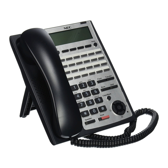
ISSUE 1.0 SL1100 5 INSTALLING THE MULTILINE TELEPHONES AND ECTION OPTIONAL TERMINALS 5.1 Installing the Multiline Telephones There are three types of Multiline Telephones available in the SL1100 system. • IP4WW-12TXH-B-TEL • IP4WW-24TXH-B-TEL • IP4WW-24TIXH-C-TEL (IP) 5.1.1 Location of Controls Handset... -
Page 92: Multiline Telephone Legs Adjustment
SL1100 ISSUE 1.0 Functions 12TXH 24TXH 24TIXH Connected to Digital Extension Port Ethernet Port on the Network Headset Port Power Feeding AC Adapter (DC27 V,1 A) or PoE (IEEE802.3af) 5.1.2 Multiline Telephone Legs Adjustment The Multiline Telephone provides adjustable legs for angling the phone to best suit each user. The leg can be set for two different heights (Low/High). -
Page 93: Figure 2-91 Setting For High Position
ISSUE 1.0 SL1100 Leg Stopper Figure 2-91 Setting for High Position 3. Adjust the leg to desired height. < High position > Figure 2-92 Leg Setting for High Position 4. Lead the Line and Handset cords through the applicable grooves. -
Page 94: Wall-Mounting The Multiline Telephone
SL1100 ISSUE 1.0 5.1.3 Wall-Mounting the Multiline Telephone 1. Arrange the cables and put down the leg as shown below. Handset cord Telephone line cord < Bottom view> Figure 2-93 Cabling for Wall-Mount For IP4WW-24TIXH-C only: When wall-mounting the IP4WW-24TIXH-C, attach the IP4WW-WALL MOUNT UNIT to the bottom panel as shown. -
Page 95: Figure 2-96 Wall-Mount Screw Guide
ISSUE 1.0 SL1100 Hook-switch hanger Hook-switch hanger Figure 2-95 Hook-Switch Hanger 3. Install two screws into a wall. The screw heads must be remained about 3 mm (0.12″). 3 - 4 mm 1 - 3 mm (0.12″ - 0.16″) (0.04″ - 0.12″) 83.5 mm... -
Page 96: Install The Ip Multiline Telephone (Ip4Ww-24Tixh-C1 Tel)
SL1100 ISSUE 1.0 5.2 Install the IP Multiline Telephone (IP4WW-24TIXH-C1 TEL) 5.2.1 System Connection The IP Multiline Telephone is connected via HUB. IP Multiline Telephone LAN Cable Exit Help (10BASE-T/100BASE-TX) Flash Transfer Mute PQRS WXYZ Clear/Back Speaker Hold Ferrite Core... -
Page 97: Installing The Dss Console
The 60D DSS-B Console can be installed on any digital extension port of each 084M-B1/080E-B1 card directly. The pair extension for the DSS Console is assigned using system programming. For the settings, refer to the SL1100 Features & Specifications Manual. 5.3.1 DSS Console Leg Adjustment The DSS Console provides the leg for angling the console to best suit each user. -
Page 98: Wall-Mounting The Dss Console
SL1100 ISSUE 1.0 Leg Stopper Figure 2-102 Leg Stopper of DSS Console 3. Adjust the leg to desired height. < High position > Figure 2-103 High Position Setting 4. Lead the Line cord through the applicable grooves. (Refer to Figure 2-101 Cabling of DSS on the previous page) 5.3.2 Wall-Mounting the DSS Console... -
Page 99: Installing The Headset
ISSUE 1.0 SL1100 < Bottom view> Figure 2-104 Cabling for Wall-Mount 2. Install two screws into a wall. The screw heads must be remained about 3 mm (0.12″). 3 - 4 mm 1 - 3 mm (0.12″ - 0.16″) (0.04″ - 0.12″) 83.5 mm... -
Page 100: Installing The Doorphone Box
<Recommended Headset> • HW251N-A10-NE This Item is made by Plantronics, inc. For the details of setting and operation, refer to the SL1100 Feature & Specifications Manual. (separate issue) The headset configuration is assigned using system programming. 5.5 Installing the Doorphone Box 5.5.1 Wall-Mounting the Doorphone... -
Page 101: Figure 2-109 Doorphone Box And Bracket
ISSUE 1.0 SL1100 Wall-mount bracket Upper housing Screw terminals Screw Connect cable Figure 2-109 Doorphone Box and Bracket 4. Mount the Wall-Mount bracket on the wall using supplied screws. 5. Replace the Upper housing and tighten the screw. Hole Wall-mount... -
Page 102: Connecting The Doorphone
SL1100 ISSUE 1.0 5.5.2 Connecting the Doorphone J421 J103 J431 J411 J102 J101 RY1/2 SLI 9-12 /DPH 1-2 Port 1 Port 2 Port 3 Port 4 T : Tip R : Ring Modular Cable (2-wire, Straight) Doorphone Figure 2-111 Connecting the Doorphone The Doorphone configuration is assigned using system programming. -
Page 103: Installing The Door Unlock Devices
ISSUE 1.0 SL1100 5.6 Installing the Door Unlock Devices A maximum of two door unlock devices can be connected to each KSU. J7 (RJ61) 8 765 4321 RY1/2 Door unlock control devices Figure 2-112 Connecting the Door Unlock Device The following table shows the pin-outs for the RJ-61 cable connector. -
Page 104: Installing The External Paging Speaker/External Moh/Bgm Sources
SL1100 ISSUE 1.0 5.7 Installing the External Paging Speaker/External MOH/BGM Sources 5.7.1 Connecting the Audio Equipment • The audio jack labeled PAGE, MOH, BGM can be used for audio port (External paging, External MOH, BGM) • Audio port configuration is assigned using system programming. -
Page 105: Bgm/External Moh Source Input Specifications
ISSUE 1.0 SL1100 5.7.3 BGM/External MOH Source Input Specifications Table 2-26 BGM/External MOH Source Input Specifications Item Specification Input Impedance @ 1 kHz Input Level Nominal 250 mV (-10 dBm) Maximum Input 1 V RMS 5.8 SMDR (Station Message Detail Recording) 5.8.1 General... -
Page 106: Section 6 Installing Wireless Dect Telephones
6 INSTALLING WIRELESS DECT TELEPHONES ECTION 6.1 Installing the DTL-8R-1 Cordless DECT Telephone DTL-8R-1 is a cordless telephone that is adapted for NEC SL1100 System. It is designed for use in the office environment. Figure 2-115 Cordless DECT Telephone (DTL-8R-1) •... -
Page 107: Installation Precautions
1. Connect the cord from the telephone jack to the Line In on the DTL-8R-1 Cordless DECT. Figure 2-117 Connecting Telephone Cords to the Telephone Jack 2. Connect a SL1100 digital multiline terminal to the DTL-8R-1 Cordless DECT. Line "OUT"... -
Page 108: Applying Power To The Charging Unit
SL1100 ISSUE 1.0 6.1.4 Applying Power to the Charging Unit The unique design of the telephone allows the user to place the handset in the charging unit with or without the belt clip attached. The charging unit can charge a second battery with or without the handset being charged. -
Page 109: Figure 2-121 Attaching The Wall Mount Stand To The Base Unit
4. Plug one end of the short telephone cord (locally supplied) in the LINE jack on the base unit. Plug one end of the SL1100 digital multiline terminal into the PHONE jack. Place the telephone cords inside the molded channels on the bottom of the wall mount stand. -
Page 110: Mounting The Base Directly To The Wall
SL1100 ISSUE 1.0 Figure 2-123 Placing the Base Unit on the Posts of the Wall Plate Because of variation in wall plates, this method is not recommended. 7. Plug the AC adapter into a standard 120 Vac wall outlet. Do not use an outlet controlled by a wall switch. -
Page 111: Figure 2-125 Inserting Screws Into The Wall For Wall Mounting The Telephone
4. Plug one end of the short telephone cord into the LINE jack on the base unit. Then plug one end of a SL1100 multiline terminal into the PHONE jack. Place the telephone cords inside the molded channels on the bottom of the wall mount stand. -
Page 112: Wall Mounting The Charging Unit
SL1100 ISSUE 1.0 6. Plug the other end of the short telephone cord into a telephone wall jack. 7. Plug the AC adapter into a standard 120 Vac wall outlet. Refer to Figure 2-124 Plugging the AC Adapter into the AC Wall Outlet on page 2-76. -
Page 113: Attaching And Removing The Belt Clip
ISSUE 1.0 SL1100 Figure 2-130 Placing the Charging Unit on the Wall 4. Plug the AC adapter into a standard 120 Vac wall outlet. Refer to Figure 2-130 Placing the Charging Unit on the Wall on this page. 6.1.8 Attaching and Removing the Belt Clip A belt clip can be used to attach the handset to a belt or pocket for convenient portability. -
Page 114: Installing The Handset Battery Pack
SL1100 ISSUE 1.0 Figure 2-132 Removing the Belt Clip 6.1.9 Installing the Handset Battery Pack term Before installing batteries, refer to D ® Cordless DECT Owner’s Manual Specifications and Battery Safety. It is important to follow safety regulations when handling batteries. -
Page 115: Charging Batteries
ISSUE 1.0 SL1100 Figure 2-135 Replacing the Battery Cover 6.1.10 Charging Batteries The rechargeable battery pack must be fully charged before using the DTL-8R-1 Cordless DECT for the first time. Charge the battery pack without interruption for five to eight hours. -
Page 116: Installing The Dtl-Rpt-1 Cordless Dect Telephone Repeater
SL1100 ISSUE 1.0 6.2 Installing the DTL-RPT-1 Cordless DECT Telephone REPEATER The UDR100 repeater lets you extend the coverage area of your cordless DECT telephone system in all directions. Figure 2-136 Cordless DECT Telephone Repeater DTL-RPT-1 If the repeaters are installed so their coverage area overlaps the coverage area of the base, the base can hand-off calls to the repeaters as the user moves from one coverage area to another. -
Page 117: Figure 2-137 Single Repeater Attached To Base
ISSUE 1.0 SL1100 the end user, even during an active call. Figure 2-137 Single Repeater Attached to Base Each base supports up to six repeaters, so you can extend coverage in all directions, including through floors and ceilings: Figure 2-138 Six Repeaters Attached to Base... -
Page 118: Setting Up Your Repeater
SL1100 ISSUE 1.0 In addition, the UDR100 supports a sequential or "daisy-chain" layout to extend coverage in a single direction. Up to three repeaters can be installed in sequence: Figure 2-139 Daisy-Chain Layout For detailed information on daisy-chain layout and configuration, contact your installer or refer to the UDR100 Administrator's Guide. -
Page 119: Installing The Repeater
ISSUE 1.0 SL1100 2. Reconnect the power to the repeater. The LED on the repeater flashes slowly, indicating the repeater is in registration mode. The repeater stays in registration mode for five minutes. If you cannot complete the registration in five minutes, repeat the procedure starting with step 1. - Page 120 SL1100 ISSUE 1.0 6.2.2.2 Map the Base Coverage Area To find the best location for the repeater, you need to determine the base coverage area. Stand near the base and make a call. Walk away from the base with the handset, and make a note where the signal becomes weaker.
-
Page 121: Figure 2-141 Incorrect Installation
ISSUE 1.0 SL1100 6.2.2.5 Multiple Repeater Systems You can register up to six repeaters to one base as long as the repeaters are a minimum of 30 feet apart. Remember that the signal can cross through walls and floors. Incorrect Installation Figure 2-141 Incorrect Installation on this page illustrates repeaters that are incorrectly installed. -
Page 122: Troubleshooting Chart
SL1100 ISSUE 1.0 You can combine normal and daisy-chain connections to create a wide variety of coverage configura- tions, as long as you have no more than six repeaters per base unit. Figure 2-143 Daisy-Chain Layout 6.2.3 Troubleshooting Chart To review common problems and possible solutions, refer to the Cordless DECT Repeater Guide DTL-RPT-1. -
Page 123: Connecting The Base Station
ISSUE 1.0 SL1100 6.3.1 Connecting the Base Station Figure 2-144 Base Station Front and Back View on this page provides a front and rear view of the base station. Front View Rear View Figure 2-144 Base Station Front and Back View If your network connection does not provide Power Over Ethernet, you will need to order a base station AC adapter and a standard Ethernet-to-PoE adapter. -
Page 124: Wall Mounting The Base Station
SL1100 ISSUE 1.0 Figure 2-145 Connecting the Base Station 3. Connect the other end of the cable to your TCP/IP network. When the base station powers on, the STATUS LED on the front briefly lights orange and then turns off while it initializes and connects to the network. After the base station successfully initial- izes and connects to the network, the LED lights green and remains steady on. -
Page 125: Figure 2-146 Base Mounting Dimensions
ISSUE 1.0 SL1100 Figure 2-146 Base Mounting Dimensions 2. Insert the appropriate anchors for the wall material. 3. Insert the mounting screws into the anchors, leaving about 1/4 inch of space between the screw head and the wall. 4. Connect the Ethernet cable and route the cord as shown in... -
Page 126: Handset And Charger
SL1100 ISSUE 1.0 6.3.3 Handset and Charger Figure 2-147 Handset Front View on this page provides a front view of the handset and Figure 2-148 Charger Top View on the next page provides a top view of the charger. Figure 2-147 Handset Front View... -
Page 127: Figure 2-149 Installing The Handset Battery
ISSUE 1.0 SL1100 Figure 2-148 Charger Top View 6.3.3.1 Charging the Battery Follow the steps below to charge the battery. 1. Install the handset battery as shown below in Figure 2-149 Installing the Handset Battery on this page. Figure 2-149 Installing the Handset Battery 2. -
Page 128: Figure 2-150 Inserting Handset Into The Charger
SL1100 ISSUE 1.0 4. Place the spare battery (if available) in the back section of the charger; the BATTERY STATUS LED should turn on. (Pull the battery latch back slightly to fit the battery in the slot.) See Figure 2-150 Inserting Handset into the Charger on the previous page. -
Page 129: Chapter 3 System Start Up
System Start Up 1 SYSTEM START UP ECTION 1.1 Before Starting Up the System Before starting up the system, make sure: • KSU(s) are installed correctly. • All extensions are cabled correctly. • All earth ground and PSTN Trunks are cabled correctly. •... -
Page 130: Perform A Cold Start
SL1100 ISSUE 1.0 1.2.1 Perform a Cold Start This section describes the process for starting the system for the first time or starting a system that requires the customer data be deleted. System software is loaded from flash memory, and the customer data is deleted from RAM memory. -
Page 131: Perform A Hot Start
ISSUE 1.0 SL1100 5. Continue holding the LOAD button (S1) for approximately three seconds or until Status LED (D5) starts flashing red. RUN LED LED (D5) < Front view > Figure 3-4 Status LED (D5) and RUN LED Location 6. Release the LOAD button. -
Page 132: Section 2 Programming Mode
Base Service OP1 OP2 Figure 3-7 Entering Programming Mode Display 2 For the details of programming, refer to the SL1100 Programming Manual. (separate issue) 2.2 Exiting the Programming Mode 1. Press Mute key several times to return to the "Program Mode" Screen. -
Page 133: Loading The Customer Data
ISSUE 1.0 SL1100 CPU card CF Slot (CN2) CF card VMDB Figure 3-10 Inserting the CF card 2. Turn the power on, enter the Program Mode then PRG90-03. 90-03-01 Program Mode Data Save YES:1 1 Base Service OP1 OP2 Figure 3-11 PRG90-03 Display 3. -
Page 134: Figure 3-13 Inserting The Cf Card
SL1100 ISSUE 1.0 CPU card CF Slot (CN2) CF card VMDB Figure 3-13 Inserting the CF card 2. Turn the power on, enter the Program Mode then PRG90-04. 90-04-01 Program Mode Data Load YES:1 1 Base Service OP1 OP2 Figure 3-14 PRG90-04 Display 3. -
Page 135: Section 3 System Shut Down
ISSUE 1.0 SL1100 3 SYSTEM SHUT DOWN ECTION 3.1 Powering Off the System 1. Turn the all KSU(s) power off using the power switch. Figure 3-16 Power Switch Location • If Expansion KSU(s) are installed, turn the power on/off in the order of Expan- sion 2 KSU, Expansion 1 KSU and then Main KSU. - Page 136 SL1100 ISSUE 1.0 Memo System Start Up...
-
Page 137: Chapter 4 Maintenance
Maintenance 1 FUSE REPLACEMENT ECTION 1.1 Replacing the Fuse This fuse is only for external battery box connection, it is not used for AC power to the system. If Expansion KSU(s) are installed, turn the power on/off in the order of Expan- sion 2 KSU, Expansion 1 KSU and then Main KSU. -
Page 138: Figure 4-2 Removing The Main-Cover
SL1100 ISSUE 1.0 Main-Cover Two screws Hooks Figure 4-2 Removing the Main-Cover 4. Exchange the fuse (250 V/8 A) on 084M-B1 PCB. 084M-B1 FUSE (8 A / 250 V) < Top View > Figure 4-3 Exchanging the Fuse 5. Replace the Main-Cover and fasten two screws. -
Page 139: Figure 4-4 Replacing The Main-Cover
ISSUE 1.0 SL1100 Main-Cover Two screws Hooks Figure 4-4 Replacing the Main-Cover Hardware Manual... -
Page 140: Section 2 Lithium Battery Replacement
Before replacing the Lithium battery, make sure which type of Lithium battery is required and prepare the new Lithium battery. (CR2032) NEC recommends that a backup of the customer data is performed before powering off the system (either PCPro file or CF card backup) in order to replace the backup battery. -
Page 141: Figure 4-7 Disconnecting The Ac Power Cord
ISSUE 1.0 SL1100 2. Power off the system, and remove the AC plug from the AC outlet. 3. Disconnect the AC power cord from the KSU. AC power cord must be disconnected, otherwise the Main-Cover cannot be opened. Disconnect AC Power Cord Figure 4-7 Disconnecting the AC Power Cord 4. -
Page 142: Figure 4-9 Removing The Cpu Card
SL1100 ISSUE 1.0 CPU card CPU support 084M-B1 at 1228M KSU Figure 4-9 Removing the CPU Card 7. Refer to following figure for the Lithium battery location on the CPU card. CPU card Battery socket < Conductor side > Figure 4-10 Location of Lithium Battery Socket 8. -
Page 143: Figure 4-12 Inserting The Lithium Battery
ISSUE 1.0 SL1100 Lithium battery Socket Figure 4-12 Inserting the Lithium Battery 9. Reinstall the CPU card into the 084M-B1 mother board and close the CPU support bracket. CPU card CPU support 084M-B1 at 1228M KSU Figure 4-13 Installing the CPU Card 10. -
Page 144: Section 3 Main Software Upgrading
Before upgrading the main system software, the following preparations are necessary. • Prepare the CF Card (32MB, or upwards and formatting by FAT(16)), and store the new main software on the CF card by PC. (New main system software is supplied by NEC.) 3.3 Main Software Version Confirmation The main system software version is confirmed by the following operation at the display type Multiline Telephone. -
Page 145: Upgrading The Main Software
ISSUE 1.0 SL1100 5. Off-Hook and return to Time & Date mode. 11-10 WED 1:49PM Menu Dir VM:00 CL:00 3.4 Upgrading the Main Software If Expansion KSU(s) are installed, turn the power on/off in the order of Expan- sion 2 KSU, Expansion 1 KSU and then Main KSU. -
Page 146: Table 4-1 Status Leds
SL1100 ISSUE 1.0 CPU card CF Slot (CN2) VMDB CF card D2 (Red) D1 (Blue) D3 (Red) D4 (Red) D5 (Red) Figure 4-17 Inserting the CF card 5. Push in and hold the LOAD button (S1 on the CPU card). -
Page 147: Figure 4-19 Removing The Cf Card
ISSUE 1.0 SL1100 CPU card CF Slot (CN2) CF card VMDB Figure 4-19 Removing the CF card 11. Replace the Main-Cover and Sub-Cover. 12. Turn the system power back on. 13. When the system has completed reloading the software, the RUN LED (D1) will flash blue. -
Page 148: Section 4 Led Indications
SL1100 ISSUE 1.0 4 LED INDICATIONS ECTION The LEDs on the CPU indicate the following: • RUN (D1) = The CPU is operating (Blue) • D2, and D3 = Alarms (Red) • D4 = Flash access indication (Red) • D5 = Boot status (Red) •... -
Page 149: Section 1 System Capacity
Specifications 1 SYSTEM CAPACITY ECTION Table 5-1 System Capacity Items 1 KSU 2 KSU 3 KSU Note (1228) (2456) (3684) Expansion Slot System Maximum Port 1KSU: 084M+PRI+080E+4COIDBx2 2KSU: (084M+PRI+080E)x2+4COIDBx4 3KSU: 084Mx3+PRIx2+080Ex4+4COIDBx7 Trunk Port Max. 1KSU: PRIx1+4COIDBx2 2KSU: PRIx2+4COIDBx4 3KSU: PRIx2+4COIDBx7 Trunk Port Analog Trunks 1KSU: 4COIDBx3 on 084M/080E/008E... - Page 150 SL1100 ISSUE 1.0 Items 1 KSU 2 KSU 3 KSU Note (1228) (2456) (3684) Ethernet Port 1 circuit on CPU Built-In Answering Machine 2 circuits on CPU Channel VoIP Channels Port increased by license. V.34 Modem 1 circuit on CPU-B1 (VMDB) Conference Circuits 32 (Max.
-
Page 151: Section 2 System Specifications
ISSUE 1.0 SL1100 2 SYSTEM SPECIFICATIONS ECTION 2.1 General Precautions • Never attempt to insert wires, pins, etc. into the vents or other holes of the equipment. • Do not use benzene, thinner, or the like, or any abrasive powder to clean the equipment. Wipe it with a soft cloth. -
Page 152: Electrical Specifications
SL1100 ISSUE 1.0 110VAC 120VAC 220VAC 230VAC 240VAC Phase and Wire Single Phase, 2 Line + PE Type Ground Requirement No.14 AWG Copper Wire Feeding Voltage SLT: 20 mA/-27 V AC Input I Main KSU = Main KSU = Main KSU =...(Ksu) -
Page 153: Mechanical Specifications
ISSUE 1.0 SL1100 2.9 Mechanical Specifications Table 5-7 Mechanical Specifications Equipment Width Depth Height Weight Note 1228M-B KSU, 375 mm 115 mm 290 mm Approx. 2 kg 1228ME-B EXP (14.76 in) (4.53 in) (11.42 in) (70.55 oz) External Backup Battery... -
Page 154: General Purpose/Door Unlock Relay Specifications
SL1100 ISSUE 1.0 2.12 General Purpose/Door Unlock Relay Specifications Table 5-10 General Purpose/Door Unlock Relay Specifications Item Specification Rated Voltage DC 48 V Maximum Rated Current DC 320 mA Maximum Contact Normally Open 2.13 External Paging Output Specifications Table 5-11 External Paging Output Specifications... -
Page 155: Cabling Requirements
ISSUE 1.0 SL1100 2.17 Cabling Requirements • Do not run extension cable in parallel with the AC source, telex or computer etc. If the cables are near cable runs to those devices, use shielded cable with grounded shields or install the cable in conduit. - Page 156 SL1100 ISSUE 1.0 Memo Specifications...
- Page 157 ISSUE 1.0 SL1100 Memo Hardware Manual...
-
Page 158: Hardware Manual
Hardware Manual NEC Corporation ISSUE 1.0...
Need help?
Do you have a question about the SL1100 and is the answer not in the manual?
Questions and answers