NEC SL1100 Hardware Manual
Hide thumbs
Also See for SL1100:
- Features and specifications manual (864 pages) ,
- Programming manual (646 pages) ,
- Networking manual (292 pages)
Table of Contents
Advertisement
Quick Links
Advertisement
Table of Contents
Troubleshooting

Related Manuals for NEC SL1100


Summary of Contents for NEC SL1100
- Page 1 Hardware Manual A50-031693-003 NA ISSUE 5.0...
- Page 2 Copyright NEC Corporation reserves the right to change the specifications, functions, or features at any time without notice. NEC Corporation has prepared this document for use by its employees and customers. The information contained herein is the property of NEC Corporation and shall not be reproduced without prior written approval of NEC Corporation.
-
Page 3: Table Of Contents
2.5.3 ML440 and AP20 Wireless DECT Telephone....... 1-9 2.6 Call Logging Unit (V3.0 or higher)..........1-10 2.6.1 NEC 1-port Digital Call Logging Unit........... 1-10 2.6.2 NEC 1-Port IP Call Logging Unit (V4.0 or higher)....... 1-10 Section 3 SYSTEM CAPACITY............1-11 3.1 System Capacity................1-11 3.2 KSU Capacity................ - Page 4 SL1100 ISSUE 5.0 1.1.3 Site Requirements................. 2-1 1.1.4 Environmental Requirements............2-2 1.1.5 Unpacking..................2-2 Installing the Main KSU (1228M-B KSU)........2-2 1.3 Wall-Mounting the KSU(s).............. 2-3 1.3.1 KSU Dimensions................2-3 1.3.2 Wall Installation of KSU..............2-4 1.3.3 Mounting Procedure of KSU............2-6 1.4 Installing the Expansion KSU(s).............
- Page 5 ISSUE 5.0 SL1100 3.5.1 General..................2-57 Section 4 INSTALLING THE OPTIONAL INTERFACE CARDS..2-59 4.1 VoIP Card (VOIPDB-C1) ............. 2-59 4.1.1 General..................2-59 4.1.2 Unpacking................... 2-59 4.1.3 Installing the VOIPDB-C1 PCB........... 2-59 4.1.4 LED Indication................2-63 4.2 Installing the CF Card (CFVMS/CFVML)........2-63 Section 5 INSTALLING THE MULTILINE TELEPHONES AND OPTIONAL TERMINALS........
- Page 6 HIGHER)..............2-120 7.1 NEC Digital Call Logger.............. 2-120 7.1.1 NEC 1-Port Digital Logging Unit..........2-120 7.2 NEC IP Call Logger (V4.0 or higher).......... 2-123 7.2.1 NEC 1-Port IP Call Logging Unit..........2-123 7.3 NEC Digital Player Requirements..........2-130 7.3.1 Hardware and Software Requirements........2-130 7.4 NEC Digital Player/Recorder Installation........
- Page 7 ISSUE 5.0 SL1100 2.4 Loading the Customer Data............3-6 Section 3 SYSTEM SHUT DOWN............. 3-8 3.1 Powering Off the System..............3-8 3.2 Resetting the System..............3-8 Chapter 4 Maintenance Section 1 FUSE REPLACEMENT............. 4-1 1.1 Replacing the Fuse................. 4-1 Section 2 LITHIUM BATTERY REPLACEMENT......4-4 2.1 General...................
- Page 8 SL1100 ISSUE 5.0 LIST OF TABLES Table 1-1 System Capacity ..................... 1-11 Table 2-1 KSU Packing List....................2-2 Table 2-2 Items on the CPU card..................2-3 Table 2-3 EXIFB-C1 Packing List..................2-9 Table 2-4 Connectors of EXIFB-C1................... 2-9 Table 2-5 Power Requirement..................2-14 Table 2-6 RJ61 Cable Connector Pin-Outs (J101-J103)..........
- Page 9 ISSUE 5.0 SL1100 LIST OF FIGURES Figure 1-1 System Configuration (V3.5 or higher)............. 1-1 Figure 1-2 System Image ....................1-13 Figure 1-3 Maximum KSU Capacity - Expandability of Trunk and Extension (without PRI) .................... 1-14 Figure 1-4 Maximum KSU Capacity - Expandability of Trunk and Extension (with PRI) ......................
- Page 10 SL1100 ISSUE 5.0 Figure 2-46 Securing the Battery Box................2-33 Figure 2-47 Removing the Front Cover ................2-33 Figure 2-48 Removing the L-Bracket ................2-34 Figure 2-49 Securing the L-Bracket and WM Hook............2-35 Figure 2-50 Attaching the KSU..................2-35 Figure 2-51 KSU Mounting on Battery Box..............
- Page 11 ISSUE 5.0 SL1100 Figure 2-99 IP Multiline Telephone Connection............... 2-70 Figure 2-100 IP Multiline Telephone Connectors............. 2-70 Figure 2-101 Low Position Setting................... 2-71 Figure 2-102 Cabling of DSS................... 2-72 Figure 2-103 Leg Stopper of DSS Console..............2-72 Figure 2-104 High Position Setting.................. 2-73 Figure 2-105 Cabling for Wall-Mount................
- Page 12 SL1100 ISSUE 5.0 Figure 2-152 Single Repeater Attached to Base............2-105 Figure 2-153 Six Repeaters Attached to Base............... 2-106 Figure 2-154 Daisy-Chain Layout.................. 2-106 Figure 2-155 Combo Star and Daisy-Chain Layout............2-107 Figure 2-156 Back View of the DTL-RPT-2 Repeater............ 2-108 Figure 2-157 Removing the Adapter Cover..............
- Page 13 ISSUE 5.0 SL1100 Figure 3-16 Power Switch Location................... 3-8 Figure 4-1 Removing the Sub-Cover................. 4-1 Figure 4-2 Removing the Main-Cover................4-2 Figure 4-3 Exchanging the Fuse..................4-2 Figure 4-4 Replacing the Main-Cover................4-3 Figure 4-5 Warning of Low Battery..................4-4 Figure 4-6 Removing the Sub-Cover.................
- Page 14 SL1100 ISSUE 5.0 MEMO Hardware Manual...
-
Page 15: Section 1 General Information
The telephone company may make changes in its technical operations and procedures. When such changes affect the compatibility or use of the SL1100 system, the telephone company is required to give adequate notice of the changes in order for you to maintain uninterrupted service. -
Page 16: Toll Restriction And Least Cost Routing Equipment
The consumer/purchaser/supplier instructions accompanying this equipment and/or software features must contain the following notice: • The software contained in the SL1100 to allow user access to the network must be upgraded to recognize newly established network area codes and exchange codes as they are placed into service. -
Page 17: Equal Access Requirements
AC power sources. This has been identified as a major nationwide problem. HEARING AID COMPATIBILITY NEC Multiline Terminals and NEC Single Line Telephones that are provided for this system are hearing aid compatible. The manufacturer of other Single Line Telephones for use with the system must provide notice of hearing aid compatibility to comply with FCC rules that now prohibit the use of non-hearing aid compatible telephones. -
Page 18: Music On Hold
When equipped with the 1228M/ME-B KSU, the SL1100 can be operated as a Class B device. SAFETY INFORMATION This equipment has been certified by CSA International and found to comply with all Applicable safety requirements: •... -
Page 19: Battery Disposal
Classe A prescrites dans le reglement sur le brouillage radioelectrique edicte par Industrie Canada. BATTERY DISPOSAL The SL1100 system includes the batteries listed below. When disposing of these batteries, KSU, and/or Unit, you must comply with applicable federal and state regulations regarding proper disposal procedures. -
Page 20: Electromagnetic Compatibility
For an overview of the supported features, refer to the detailed documentation that comes with this system, contact your local NEC Unified Solutions representative or the support desk of NEC Unified Solutions. -
Page 21: Battery Information
If your electrical and electronic products must be disposed of please refer to your supplier or the contractual agreements that your company has made upon acquisition of these products. At www.nec-unified.com/weee you can find information about separate disposal and environmentally sound recycling. BATTERY INFORMATION Defective or exhausted batteries should never be disposed of as municipal waste. - Page 22 SL1100 ISSUE 5.0 MEMO Regulatory...
-
Page 23: Figure 1-1 System Configuration (V3.5 Or Higher)
Two more expansion KSUs provide a maximum of 36 analog trunks and 72 Multiline terminals. The SL1100 is also equipped to support Digital Network (PRI, T1) and IP Trunks (SIP) or IP extensions. Also, the SL1100 initially bundles Voice Mail and MEMDB. -
Page 24: Section 2 Equipment List
SL1100 ISSUE 5.0 2 EQUIPMENT LIST ECTION The following table lists all equipment for the SL1100 system. Stock Number Equipment Name Equipment Description Note 1100001 SL1100 TDM Basic Kit SL1100 Basic Kit (4x8x4) (4x8x4) <Including> IP4NA-1228M-B KSU, IP4WW-4COIDB- B1, IP4WW-12TXH-B-TEL (BK) (3 sets) - Page 25 730649 DTL-RPT-2 Repeater Repeater for DTL-8R-1 (V1.5 Added) 730651 AP20 Base Unit Base Unit for ML440 730650 ML440 Multiline Wireless ML440 Multiline Wireless Handset Handset 780275 NEC 1-Port Digital Log- 1-Port Digital Logging Unit (V3.0 Added) ging Unit Hardware Manual...
-
Page 26: Ksus And Optional Unit
SL1100 ISSUE 5.0 Stock Number Equipment Name Equipment Description Note 780324 NEC 1-Port IP Logging 1-Port IP Logging Unit (V4.0 Added) Unit 808920 Installation Cable - Open Provides connection to MDF for line and station ports Ended 25 pair with (6) 8- pin Plugs 2.1 KSUs and Optional Unit... -
Page 27: Ip4Ww-Exifb-C1
ISSUE 5.0 SL1100 The EXIFE DSP provides: • 32 telephony resources (DTMF/Dial tone/Busy tone/FSK caller-ID receiver/sender) The 1228ME-B EXP does NOT have CPU and main software and cannot be used in a stand-alone mode. 2.1.3 IP4WW-EXIFB-C1 Using a Cat5 cable, EXIFB-C1 card installed in the Main KSU is individually connected to each EXIFE-C1 card (Expansion KSU). -
Page 28: Ip4Ww-008E-B1
ISDN Primary Rate Interface, T1 Interface. A total of two 1PRIUs can be installed per system or one 1PRIU per KSU. With SL1100 V1.5 and higher, the 1PRIU can be installed in the 3rd expansion slot (slots 10,11,12 respectively) in each cabinet. -
Page 29: Optional Interface Cards
ISSUE 5.0 SL1100 2.3 Optional Interface Cards 2.3.1 IP4WW-VOIPDB-C1 The VOIPDB-C1 card provides the RTP/RTCP voice processing function. • Mount this card onto the CPU card (VoIPDB slot) at Main KSU. • Max. 32 channels by license control. 2.3.2 IP4WW-CFVMS-C1/IP4WW-CFVML-C1 Two types of VRS/VM CF cards are available: •... -
Page 30: Ip4[ ]-24Tixh-C Tel
The Wireless Headset Adapter allows you to connect a Plantronics Wireless Headset System directly to your SL1100 telephone’s headset socket. The Wireless Headset Adapter tightly integrates your headset system with the SL1100 to provide enhanced wireless mobility and call answering. The Plantronics lifter is not required. Introduction... -
Page 31: Itx-1De-1W(Bk) Tel (V5.0 Or Higher)
2.5 Wireless DECT Telephones 2.5.1 DTL-8R-1 Cordless DECT Telephone DTL-8R-1 is a single-cell cordless DECT telephone that is adapted for digital NEC SL1100 system. It is designed for use in the office environment. The following are included with the DTL-8R-1 Cordless DECT Telephone. -
Page 32: Call Logging Unit (V3.0 Or Higher)
2.6.2 NEC 1-Port IP Call Logging Unit (V4.0 or higher) The NEC 1-Port IP Call Logging Unit is a USB device that can record SIP audio in one of two ways. SIP audio can be recorded by installing the Call Logging Unit in line with the SIP phone thus recording only those calls to or from the selected SIP phone. -
Page 33: Section 3 System Capacity
ISSUE 5.0 SL1100 3 SYSTEM CAPACITY ECTION 3.1 System Capacity Table 1-1 System Capacity Items 1 KSU 2 KSU 3 KSU 4 KSU Description Note (1228) (2456) (3684) (48112) (V3.5 Added) Expansion Slot Expansion Slot 3rd optional slot of each KSU can (V1.5 Add-... - Page 34 SL1100 ISSUE 5.0 Items 1 KSU 2 KSU 3 KSU 4 KSU Description Note (1228) (2456) (3684) (48112) (V3.5 Added) Station 2W Key Set Max. 24/KSU Port 084M+080Ex2 SLT (–28V) 1KSU: 084M+008Ex2 2KSU: 084Mx2+008Ex6 3KSU: 084Mx3+008Ex9 4KSU: 084Mx4+008Ex8 (V3.5) 2W DSS...
-
Page 35: Ksu Capacity
ISSUE 5.0 SL1100 3.2 KSU Capacity Enhancements • The 1PRIU-C1 (PRIU) mounted to the 3rd Option Slot required Main software V1.5 or higher and no other expansion interface card is mounted to the 3rd Optional Slot. • The 000E-B1 PCB mounted on the KSU required Main software V1.5 or higher. -
Page 36: Expandability Of Trunk And Extension (Without Pri)
SL1100 ISSUE 5.0 3.2.1 Expandability of Trunk and Extension (without PRI) (Trunk) 1228ME EXP exp. KSU) 1228ME EXP exp. KSU) 1228ME EXP exp. KSU) 1228M KSU (Extension) Detail of one KSU Example 1: 084M + 4Trk, (8Ext + 4Trk) x 2... -
Page 37: Expandability Of Trunk And Extension (With Pri)
ISSUE 5.0 SL1100 3.2.2 Expandability of Trunk and Extension (with PRI) (Trunk) Max 2PRI in four KSUs. 1228ME EXP 1228ME EXP exp. KSU) exp. KSU) 1228ME EXP exp. KSU) 1228M KSU (Extension) Detail of PRI installed KSU Example 1: 084M + 4Trk, 8Ext + 4Trk, 8Ext, PRI x 1 opt. - Page 38 SL1100 ISSUE 5.0 MEMO 1-16 Introduction...
-
Page 39: Chapter 2 Installation
Installation 1 INSTALLING THE MAIN & EXPANSION KSU ECTION 1.1 Before Installing the KSU(s) 1.1.1 General Precautions • To avoid shock or equipment damage, do not plug in or turn the system power on before completing the installation process. • Avoid working with the Equipment during electrical storms. •... -
Page 40: Environmental Requirements
SL1100 ISSUE 5.0 1.1.4 Environmental Requirements Meeting established environmental standards maximizes the life of the system. Make sure that the site is not: • In direct sunlight or in hot, cold or humid places. • In dusty areas or in areas where sulfuric gases are produced. -
Page 41: Wall-Mounting The Ksu(S)
ISSUE 5.0 SL1100 CPU card Sub-Cover < Front view > Figure 2-1 CPU Card Location Table 2-2 Items on the CPU card Item Description S1 (LOAD) Switch for System Restart/System Reset (Cold start occurs)/Upload Software Ethernet Cable Connection (for SMDR (PC, Printer), PCPro or WebPro….etc) Pin No. -
Page 42: Wall Installation Of Ksu
SL1100 ISSUE 5.0 290 mm (11.417″) 115 mm (4.528″) 375 mm (14.764″) Figure 2-2 Dimension of the Main and Expansion KSU 1.3.2 Wall Installation of KSU The Main KSU (1228M-B) and Expansion KSU(s) (1228ME-B) be mounted on the wall. Before installing, ensure the appropriate spacing exists as shown below. -
Page 43: Figure 2-3 Vertical Arrangement Of Ksus
ISSUE 5.0 SL1100 Ceiling Minimum 200 mm (7.874″) for ventilation EXP. KSU Minimum 100 mm (3.937″) for ventilation and wiring Main KSU Minimum 300 mm (11.811″) Minimum 300 mm (11.811″) Minimum 100 mm (3.937″) Wall EXP. KSU for ventilation and wiring Minimum 100 mm (3.937″) -
Page 44: Mounting Procedure Of Ksu
SL1100 ISSUE 5.0 Ceiling Minimum 200 mm (7.874″) for ventilation Minimum Minimum Minimum Minimum Minimum 300 mm 100 mm 100 mm 100 mm 300 mm (11.811″) (3.937″) (3.937″) (3.937″) (11.811″) Wall Main KSU EXP. KSU EXP. KSU EXP. KSU Minimum 200 mm (7.874″) -
Page 45: Figure 2-6 Screw Positions
ISSUE 5.0 SL1100 Install four screws into the wall. The screw heads must stand off from the wall about 2.5 mm (0.098″) to 3.5 mm (0.138″). 2.5 mm (0.098″) - 3.5 mm (0.138″) 285 mm (11.221″) 180 mm (7.087″) 285 mm (11.221″) Figure 2-6 Screw Positions •... -
Page 46: Figure 2-8 Removing The Sub-Cover
SL1100 ISSUE 5.0 Pull out the Sub-Cover by pushing out the tabs. Sub-Cover Figure 2-8 Removing the Sub-Cover • The Sub-Cover can be opened and held in the open position. Push to hold Open Figure 2-9 Sub-Cover Open Position Align the four holes on the back of the KSU with the four screws installed in the wall. -
Page 47: Installing The Expansion Ksu(S)
ISSUE 5.0 SL1100 1.4 Installing the Expansion KSU(s) 1.4.1 General Each Expansion KSU is connected to the Main KSU individually. The EXIFB-C1 card must be installed in the Main KSU (1228M-B) . 1.4.2 Unpacking (EXIFB-C1) Unpack the EXIFB-C1 and check it against physical damage. -
Page 48: Figure 2-12 Removing The Sub-Cover
SL1100 ISSUE 5.0 Open and pull out the Sub-Cover of the Main KSU. Sub-Cover Sub-Cover Figure 2-12 Removing the Sub-Cover Loosen two screws and pull out the Main-Cover by pressing the two hooks. Main-Cover Two screws Hooks Figure 2-13 Removing the Main-Cover... -
Page 49: Figure 2-14 Exifb-C1 Pcb Installation
ISSUE 5.0 SL1100 Press tab A and lift the CPU support bracket. EXIFB-C1 PCB CPU support CPU support 084M-B1 at 1228M KSU Figure 2-14 EXIFB-C1 PCB Installation Insert the EXIFB-C1 PCB into the J1 connector on the 084M-B1 at 1228M-B KSU. -
Page 50: Ksus Inter-Connection
SL1100 ISSUE 5.0 1.4.5 KSUs Inter-connection Connect the Main KSU (1228M-B) and Expansion KSU (1228ME-B) using the cables attached to the Expansion KSU. The cable must pass two times (two rounds) through the Ferrite Core refer to Figure 2-17 Connection of KSUs on page 2-12. -
Page 51: Grounding And Ac Cabling
ISSUE 5.0 SL1100 30 - 50 mm (1.181″ - 1.969″) EXIFE-C1 PCB LAN Cable Ferrite Core Pass 2 times to Main KSU Exp. KSU < Bottom View > Figure 2-18 Installing Ferrite Core 1.5 Grounding and AC Cabling The ETH (Earth Ground Lug) is located near the power supply on each KSU. The Sub-Cover must be opened in order to access to it. -
Page 52: Ac Power Requirement
SL1100 ISSUE 5.0 Insert a grounding wire (user supplied). Tighten the screw. Connect the grounding wire to earth ground. Proper grounding is very important to protect the system from external noise and to reduce the risk of electrocution in the event of a lightning strike. -
Page 53: Trunk/Extension Cabling
• Aerial distribution wiring is not allowed. • Trunks must be installed with lightning protectors. • Do not install the DSX Terminal in the SL1100 system, it does not work properly. 1.6.3 Trunk Cabling Trunk cabling is required for the 4COIDB or 1PRIU PCBs. -
Page 54: Figure 2-21 Digital Extension Cabling
SL1100 ISSUE 5.0 DSX Terminal does not work properly when it connected. J421 J103 J431 J411 J102 J101 ESI 5-8 ESI 1-4 Port 1 Port 2 Port 3 Port 4 T: Tip Max cable length R: Ring 24AWG ( 0.5 mm) -
Page 55: Figure 2-22 Analog Extension Cabling
ISSUE 5.0 SL1100 J421 J103 J431 J411 J102 J101 SLI 9-12 /DPH 1-2 Port 1 Port 2 Port 3 Port 4 T : Tip R : Ring Modular Cable Max cable length (2-wire, Straight) 24AWG ( 0.5 mm) 1,125 m... -
Page 56: Cable Routing And Clamping
SL1100 ISSUE 5.0 Table 2-6 RJ61 Cable Connector Pin-Outs (J101-J103) Pin No. ESI 1-4 (J101), ESI 5-8 (J102): SLI 9-12/DPH 1-2 (J103): Analog 2-Wire Digital Extension Port Extension Port Connector Connector (RJ-61) (RJ-61) T4 (Tip for port 4) T4 (Tip for port 4) -
Page 57: Figure 2-24 Sub-Cover
ISSUE 5.0 SL1100 Cut and remove the Plastic Knockouts as needed from the Sub-Cover. Sub-Cover Plastic Knockouts Figure 2-24 Sub-Cover Replace the Sub-Cover. Hardware Manual 2-19... -
Page 58: Section 2 Installing The External Backup Battery
• Each KSU must have own IP4WW-Battery Box. To avoid damage to equipment, do not install the Topaz Battery Box (DX2E-32i/NX7E Battery Box) to the SL1100 system. 2.2 Unpacking Unpack the IP4WW-Battery Box and check it against the following list. Inspect for physical damage. -
Page 59: Battery Box Dimensions
ISSUE 5.0 SL1100 2.3 Battery Box Dimensions 230 mm (9.055″) 340 mm (13.386″) 500 mm (19.685″) Figure 2-25 Dimension of the IP4WW-Battery Box 2.4 Battery Specifications Table 2-8 Battery Specifications Item Data Capacity 12 V, 7.0 Am/H or equivalent (Voltage must be 12 V) Recommended Battery GS Yuasa NP7-12 (151 x 65 x 97.5 mm / 2.7 kg) -
Page 60: Figure 2-26 Removing The Front Cover
SL1100 ISSUE 5.0 Loosen two screws and remove the Front Cover. Two screws (with stopper) Front Cover Figure 2-26 Removing the Front Cover Disconnect the Battery Connection Cable from the Fuse Unit if the cable is plugged already. Battery Connection Cable... -
Page 61: Figure 2-28 Batt Stopper
ISSUE 5.0 SL1100 Loosen the screw and lift the Batt Stopper. Batt Stopper Screw Figure 2-28 Batt Stopper Pull out the Battery tray. Battery tray Figure 2-29 Pulling out the Battery Tray Loosen two screws and remove the Battery tray cover. -
Page 62: Figure 2-30 Remove The Battery Tray Bracket
SL1100 ISSUE 5.0 Remove two screws and remove the Battery tray bracket. Two screws (with stopper) Battery tray cover Two screws (M3 X 8) Battery tray bracket Figure 2-30 Remove the Battery Tray Bracket Install two batteries into the Battery tray. -
Page 63: Figure 2-32 Connecting The Battery Cables
ISSUE 5.0 SL1100 Connect the battery cables. Battery Connection Cable (black) Terminal Terminal (black) (black) Battery Connection Cable (red) Terminal Terminal (red) (red) Battery Connection Cable (blue) Two batteries < Front View > Figure 2-32 Connecting the Battery Cables Incorrect installation of batteries may damage the Fuse Unit or cause possible fire. -
Page 64: Figure 2-34 Inserting The Battery Tray
SL1100 ISSUE 5.0 11. Insert the Battery tray into the Battery Box. Battery tray Figure 2-34 Inserting the Battery Tray 12. Set the Batt Stopper bracket in place and secure with screw. Batt Stopper Screw Figure 2-35 Secure Batt Stopper Bracket... -
Page 65: Mounting The Ip4Ww-Battery Box
ISSUE 5.0 SL1100 13. Plug the Battery Connection Cable into the Fuse unit. Battery Connection Cable Fuse unit Figure 2-36 Connecting the Battery Connection Cable 14. Align tabs a to f to holes A to F on Battery Box. Slide the Front cover and tighten the two screws. -
Page 66: Figure 2-38 Bases And Support Of The Battery Box
SL1100 ISSUE 5.0 Assemble the FM/WM Base-F, Base-R and WM Support. FM/WM Base-R WM Support FM/WM Base-F Figure 2-38 Bases and Support of the Battery Box Refer to Figure 2-39 Floor-Mount Spacing Guide on page 2-28 for required spacing before drilling holes for 10 mm (0.394″) anchor bolts (locally procured). -
Page 67: Wall-Mounting The Ip4Ww-Battery Box
ISSUE 5.0 SL1100 Using the four hooks on the FM/WM Base mount the IP4WW-Battery Box on the Base. IP4WW-Battery Box Hooks Hooks FM/WM Base FM/WM Base Hooks Hooks Figure 2-40 Mounting the Battery Box Using four supplied screws, secure the IP4WW-Battery Box to the FM/WM Base. -
Page 68: Figure 2-42 Assemble Battery Box Base
SL1100 ISSUE 5.0 Plywood should first be installed on the wall where the Battery Box will be positioned. This allows secure anchoring of the screws which support the weight of the Battery Box. Using four supplied screws, secure the WM Support to the FM/WM Base-F and Base-R. - Page 69 ISSUE 5.0 SL1100 Using anchor bolts, secure the FM/WM Base to the wall. Wall Front side Front side Anchor bolt location AC inlet AC inlet side side Anchor bolt location Four Anchor bolts M10 mm (0.394″) : Maintenance space Figure 2-43 Wall-Mount Spacing Guide...
-
Page 70: Figure 2-44 Removing The Front Cover
SL1100 ISSUE 5.0 Loosen two screws and remove the Front Cover. Two screws (with stopper) Front Cover Figure 2-44 Removing the Front Cover Using the four hooks on the FM/WM Base mount the IP4WW-Battery Box to the Base. Square hole... -
Page 71: Mounting One Ksu On The Battery Box
ISSUE 5.0 SL1100 Using one supplied screw (M3x6 with washer), secure the back plane of the Battery Box to the FM/WM Base. Two screw holes (Use either one) < Front view> Figure 2-46 Securing the Battery Box 2.6.3 Mounting One KSU on the Battery Box Before wall-mounting or floor-mounting the IP4WW-Battery Box, a single KSU can be mounted on the Battery Box. -
Page 72: Figure 2-48 Removing The L-Bracket
SL1100 ISSUE 5.0 Loosen two screws and remove the L-Bracket. L-Bracket Two screws (M4 X 8) Figure 2-48 Removing the L-Bracket Turn the L-Bracket upside down. Rotate the L-Bracket 180 degrees so that the upper FACE as shown in Figure 2-48 Removing the... -
Page 73: Figure 2-49 Securing The L-Bracket And Wm Hook
ISSUE 5.0 SL1100 Using two anchor bolts (locally procured), secure the WM Hook to the wall. The WM Hook is required for securing both Floor-mount and Wall-mount cases. Anchor Bolts WM Hook Two screws (M4 X 8) L-Bracket Two screws... -
Page 74: Ip4Ww-Battery Box To Ksu Connection
2.7 IP4WW-Battery Box to KSU Connection To avoid damage to equipment, do not install the Topaz Battery Box (DX2E-32i/NX7E Battery Box) to the SL1100 system. • Make sure the system power is off. • If Expansion KSU(s) are installed, turn the power on/off in the order of Expansion 3 KSU (V3.5 or higher), Expansion 2 KSU, Expansion 1 KSU... -
Page 75: Ip4Ww-Battery Box Fuse Replacement
ISSUE 5.0 SL1100 Cut and remove Plastic Knockout from the Sub-Cover to connect Battery cable. Plastic Knockout Sub-Cover Battery cable Figure 2-53 Connecting Battery Cable Connect Battery cable from the Battery box to Battery connector on the KSU. 2.8 IP4WW-Battery Box Fuse Replacement •... -
Page 76: Figure 2-54 Removing The Front Cover
SL1100 ISSUE 5.0 Loosen two screws and remove the Front Cover. Two screws (with stopper) Front Cover Figure 2-54 Removing the Front Cover Disconnect the Battery connection cable from the Fuse Unit. Battery Connection Cable Fuse Unit Figure 2-55 Disconnecting the Battery Connection Cable... -
Page 77: Figure 2-56 Loosen The Fuse Unit Screw
ISSUE 5.0 SL1100 Loosen the screw from the Fuse Unit. Fuse Unit Screw Figure 2-56 Loosen the Fuse Unit Screw Slide Fuse Unit out of the Battery box. Replace the fuse (250VT8AL). Fuse Unit 250VT8AL Fuse Fuse Unit guide Figure 2-57 Replacing the Fuse Using the Fuse Unit guides, slide the Fuse Unit into the Battery Box. -
Page 78: Figure 2-59 Securing The Fuse Unit
SL1100 ISSUE 5.0 Secure the Fuse Unit by tightening the screw. Fuse Unit Screw Figure 2-59 Securing the Fuse Unit Reconnect the Battery Connection Cable to the Fuse Unit. Battery Connection Cable Fuse Unit Figure 2-60 Connect Battery Connection Cable... -
Page 79: Figure 2-61 Installation Of The Front Cover
ISSUE 5.0 SL1100 10. Align tabs a to f to holes A to F on Battery Box. Slide the Front Cover into position and tighten the two screws. Front cover Two screws (with stopper) Figure 2-61 Installation of the Front Cover... -
Page 80: Cards
SL1100 ISSUE 5.0 3 INSTALLING THE EXPANSION INTERFACE CARDS ECTION 3.1 General Enhancements • The 000E-B1 PCB mounted on the KSU required Main software V1.5 or higher. Up to two expansion interface cards can be installed per KSU. Table 2-9 Expansion Cards... -
Page 81: Mounting The Expansion Interface Card
ISSUE 5.0 SL1100 Items List of Contents Note IP4WW-000E-B1 000E-B1 PCB (with PKG Spacer) Nylon Spacers Metal Spacers Screws (with circular washer) IP4WW-1PRIU-C1 1PRIU-C1 PCB (with PKG Spacer) Nylon Spacers Metal Spacers Screws (with circular washer) 3.3 Mounting the Expansion Interface Card Enhancements •... -
Page 82: Figure 2-63 Removing The Main-Cover
SL1100 ISSUE 5.0 Loosen two screws and remove the Main-Cover. Main-Cover Two screws Hooks Figure 2-63 Removing the Main-Cover Insert two Nylon-spacers into the specified holes, and fasten two Metal-spacers into the specified holes. (Both Nylon and Metal spacers are provided with 080E/008E/000E/1PRIU) If no more Expansion Interface cards are to be mounted on the 1st PCB, fasten two screws to secure the 1st PCB on the top of the 080E/008E/000E/1PRIU. -
Page 83: Figure 2-65 Mounting The 2Nd Expansion Interface Card
ISSUE 5.0 SL1100 In case a 2nd PCB is mounted, insert two Nylon-spacers into the specified holes, and fasten two Metal-spacers into the specified holes. (Both Nylon and Metal spacers are provided with 080E/ 008E/000E/1PRIU) Fasten two screws to secure the 2nd PCB to the top of the 080E/008E/000E/1PRIU. -
Page 84: Figure 2-66 Mounting The 3Rd Expansion Interface Card
SL1100 ISSUE 5.0 In case a 3rd PCB (3rd optional slot can mount 1PRIU only) is mounted, insert two Nylon-spacers into the specified holes, and fasten two Metal-spacers into the specified holes. (Both Nylon and Metal spacers are provided with 1PRIU) •... -
Page 85: Figure 2-67 Mounting Three Expansion Interface Cards
ISSUE 5.0 SL1100 Following illustration shows an example for installing 3 expansion PCBs onto the KSU. 3rd PCB (1PRIU) 2nd PCB 1st PCB Figure 2-67 Mounting Three Expansion Interface Cards Cut and remove the Plastic Knockouts as required for each Expansion interface card. -
Page 86: Mounting The 4Coidb Pcb
SL1100 ISSUE 5.0 Replace the Main-cover and fasten two screws. Main-Cover Two screws Hooks Figure 2-69 Replacing the Main-cover 3.3.2 Mounting the 4COIDB PCB Cut and remove specified Plastic Knockouts on the 084M-B1/080E-B1/008E-B1/000E-B1 PCB. Plastic Knockout 084M-B1 Plastic Plastic Knockouts... - Page 87 ISSUE 5.0 SL1100 Attach the 4COIDB Label to the specified position on the 084M-B1/080E-B1/008E-B1/000E-B1 PCB. 4COIDB-B1 PCB Screw Nylon-Spacers Metal-Spacer 4COIDB Label 084M-B1/080E-B1/008E-B1 Screw /000E-B1 PCB Figure 2-71 Installing the 4COIDB-B1 The 4COIDB-B1 cannot be mounted on the 1PRIU-C1 PCB.
-
Page 88: Cabling And Setting The Expansion Interface Card
SL1100 ISSUE 5.0 Mount the 4COIDB-B1 with 084M-B1/080E-B1/008E-B1/000E-B1 PCB into the KSU. Screws 084M-B1/080E-B1/008E-B1/000E-B1 PCB and 4COIDB-B1 PCB Nylon- Spacers Metal-Spacers Figure 2-72 Mounting the 4COIDB-B1 into the KSU Replace the Main-Cover and fasten two screws. Main-Cover Two screws Hooks Figure 2-73 Replacing the Main-Cover 3.4 Cabling and Setting the Expansion Interface Card... -
Page 89: Cabling Ip4Ww-080E-B1
• Aerial distribution wiring is not allowed. • Trunks must be installed with lightning protectors. • Do not install the DSX Terminal in the SL1100 system, it does not work properly. 3.4.1 Cabling IP4WW-080E-B1 This IP4WW-080E-B1 PCB provides two RJ-61 connections for digital extensions. -
Page 90: Cabling Ip4Ww-008E-B1
SL1100 ISSUE 5.0 Table 2-11 RJ-61 Digital Connector Pin-Outs (J101, J102) Pin No. ESI 1-4 (J101), ESI 5-8 (J102): 2-Wire Digital Extension Port Connector (RJ-61) T4 (Tip for port 4) T3 (Tip for port 3) T2 (Tip for port 2) -
Page 91: Cabling Ip4Ww-000E-B1
ISSUE 5.0 SL1100 While an Analog Telephone (port) is ringing or MW-lamp is flashing on an Analog Phone (port), do not disconnect the phone from the port and or connect another type of the terminal to this port. 3.4.2.1 Connectors The following table shows the pin-outs for the RJ-61 cable connector for Analog extension connections. -
Page 92: Cabling And Setting Ip4Ww-1Priu-C1
SL1100 ISSUE 5.0 3.4.4.1 Connectors The following table shows the pin-outs for the RJ-61 cable connector for CO (J2) and PF (J3) connections. Table 2-13 RJ-61 CO/PF Pin-Outs (J2, J3) Pin No. CO1-4 (J2): CO Port Connector PF1 (J3): PF Tel Port Connector... -
Page 93: Table 2-14 Rj-45 Pri Pin-Outs (S-Bus, T-Bus)
ISSUE 5.0 SL1100 Table 2-14 RJ-45 PRI Pin-Outs (S-Bus, T-Bus) Pin No. RJ-45 Cable Connector- PRI 1 RJ-45 Cable Connector- PRI 1 (J5) S-Bus Connection (J5) T-Bus Connection 8 765 4321 3.4.5.2 Switch Setting The following figure shows the location of the switches and LEDs on the IP4WW-1PRIU-C1 Card. -
Page 94: Table 2-16 Led Indication
SL1100 ISSUE 5.0 IP4WW-1PRIU-C1 1.5M 2M 1.5M J8/9 D3 D4 PRI 1 (Red) (Green) Figure 2-78 Switches and LEDs Location of 1PRIU-C1 3.4.5.3 LED Indication LED indications for the IP4WW-1PRIU-C1 are listed in following table. Each LED is listed with its associated function and LED and operational status. -
Page 95: Power Failure Transfer (4Coidb-B1 Only)
ISSUE 5.0 SL1100 LED Indication Operation Status Remarks Live LED (D4) Busy LED (D3) (Green) (Red) Unit Busy A Channel is busy (use another from Ch1 - Chx) All channels are Idle. Flash 80ms (On/ Downloading firmware Off) x3/ 400ms T1 Alarm Mode Refer to following figure for LED pattern information. - Page 96 SL1100 ISSUE 5.0 Refer to Table 2-13 RJ-61 CO/PF Pin-Outs (J2, J3) on page 2-54 for wiring of the power failure telephone. • The connected extension must be SLT (Single Line Telephone). 2-58 Installation...
-
Page 97: Section 4 Installing The Optional Interface Cards
ISSUE 5.0 SL1100 4 INSTALLING THE OPTIONAL INTERFACE CARDS ECTION 4.1 VoIP Card (VOIPDB-C1) 4.1.1 General The IP4WW-VOIPDB-C1 daughter board is used to convert the RTP (Real Time Transfer Protocol) packets via the IP Network and PCM highway. The daughter board is installed on the CPU card. -
Page 98: Figure 2-81 Removing The Main-Cover
SL1100 ISSUE 5.0 Loosen two screws and remove the Main-Cover. Main-Cover Two screws Hooks Figure 2-81 Removing the Main-Cover Press tab A and lift the CPU support bracket. Remove the CPU card. CPU card CPU support 084M-B1 at 1228M KSU... -
Page 99: Figure 2-83 Installing The Voipdb-C1 Pcb
ISSUE 5.0 SL1100 Install the VOIPDB-C1 daughter board to J5 connector on the CPU card. Nylon-Spacers VOIPDB-C1 PCB CPU card Nylon-Spacers Figure 2-83 Installing the VOIPDB-C1 PCB Reinstall the CPU card into the 084M-B1 mother board, and close the CPU Support making sure tab A locks into place. -
Page 100: Figure 2-85 Removing The Plastic Knockout And Replacing The Main-Cover
Figure 2-86 Connecting a LAN Cable Refer to the SL1100 Programming Manual for detailed programming instructions. The VoIP feature requires system configuration. For the details of setting and operation, refer to the SL1100 Features & Specifications Manual (separate issue). 2-62... -
Page 101: Led Indication
ISSUE 5.0 SL1100 4.1.4 LED Indication LED indications for the IP4WW-VOIPDB-C1 are listed Table 2-19 VOIPDB LED Indications on page 2-63. Each LED is listed with its associated function and operational status. VOIPDB-C1 board LINK10 LINK100 LINK1000 < Bottom View >... -
Page 102: Figure 2-88 Installing The Cf Card
SL1100 ISSUE 5.0 • When installing a compact flash card onto the VMDB the system MUST be powered off. Never install or uninstall the compact flash card while the system is under power. Turn off the system power and disconnect AC cord. -
Page 103: And Optional Terminals
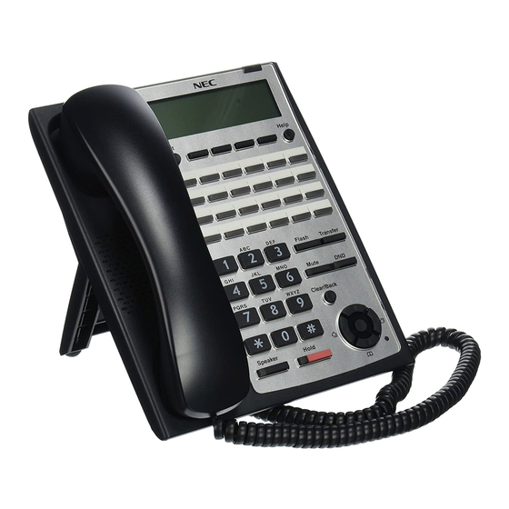
ISSUE 5.0 SL1100 5 INSTALLING THE MULTILINE TELEPHONES AND ECTION OPTIONAL TERMINALS 5.1 Installing the Multiline Telephones There are three types of Multiline Telephones available in the SL1100 system. • IP4WW-12TXH-B-TEL • IP4WW-24TXH-B-TEL • IP4WW-24TIXH-C-TEL (IP) 5.1.1 Location of Controls Handset... -
Page 104: Multiline Telephone Legs Adjustment
SL1100 ISSUE 5.0 Functions 12TXH 24TXH 24TIXH Backlit Dial Pad Incoming LED 2 colors (Red/Green) Connected to Digital Extension Port Ethernet Port on the Network Headset Port Power Feeding AC Adapter (DC27 V,1 A) or PoE (IEEE802.3af) 5.1.2 Multiline Telephone Legs Adjustment The Multiline Telephone provides adjustable legs for angling the phone to best suit each user. -
Page 105: Figure 2-92 Setting For High Position
ISSUE 5.0 SL1100 5.1.2.2 High position setting Turn telephone over (button side down). Pull up the Leg Stoppers. Leg Stopper Figure 2-92 Setting for High Position Adjust the leg to desired height. < High position > Figure 2-93 Leg Setting for High Position Lead the Line and Handset cords through the applicable grooves. -
Page 106: Wall-Mounting The Multiline Telephone
SL1100 ISSUE 5.0 5.1.3 Wall-Mounting the Multiline Telephone Arrange the cables and put down the leg as shown below. Handset cord Telephone line cord < Bottom view> Figure 2-94 Cabling for Wall-Mount For IP4WW-24TIXH-C only: When wall-mounting the IP4WW-24TIXH-C, attach the IP4WW-WALL MOUNT UNIT to the bottom panel as shown. -
Page 107: Figure 2-96 Hook-Switch Hanger
ISSUE 5.0 SL1100 Remove the switch-hook from the unit. Turn the tab toward the top. Then slide the hook-switch into position. Refer to Figure 2-96 Hook-Switch Hanger on page 2-69. Hook-switch hanger Hook-switch hanger Figure 2-96 Hook-Switch Hanger Install two screws into a wall. The screw heads must be remained about 3 mm (0.12″). -
Page 108: Install The Ip Multiline Telephone (Ip4Ww-24Tixh-C1 Tel)
SL1100 ISSUE 5.0 5.2 Install the IP Multiline Telephone (IP4WW-24TIXH-C1 TEL) 5.2.1 System Connection The IP Multiline Telephone is connected via HUB. IP Multiline Telephone LAN Cable Exit Help (10BASE-T/100BASE-TX) Flash Transfer Mute PQRS WXYZ Clear/Back Speaker Hold Ferrite Core... -
Page 109: Applying Power To The Ip Multiline Telephone
The 60D DSS-B Console can be installed on any digital extension port of each 084M-B1/080E-B1 card directly. The pair extension for the DSS Console is assigned using system programming. For the settings, refer to the SL1100 Features & Specifications Manual. 5.3.1 DSS Console Leg Adjustment The DSS Console provides the leg for angling the console to best suit each user. -
Page 110: Figure 2-102 Cabling Of Dss
SL1100 ISSUE 5.0 Lead the Line cord through the applicable grooves. Figure 2-102 Cabling of DSS 5.3.1.2 High position setting Turn DSS Console over (button side down). Pull up the Leg Stoppers. Leg Stopper Figure 2-103 Leg Stopper of DSS Console... -
Page 111: Wall-Mounting The Dss Console
ISSUE 5.0 SL1100 Adjust the leg to desired height. < High position > Figure 2-104 High Position Setting Lead the Line cord through the applicable grooves. (Refer to Figure 2-102 Cabling of DSS on page 2-72) 5.3.2 Wall-Mounting the DSS Console Lift the leg and lead the cable through the applicable grooves. -
Page 112: Installing The Headset
SL1100 ISSUE 5.0 Install two screws into a wall. The screw heads must be remained about 3 mm (0.12″). 3 - 4 mm 1 - 3 mm (0.12″ - 0.16″) (0.04″ - 0.12″) 83.5 mm (3.287″) 7 - 9.5 mm (0.28″... -
Page 113: Installing The Doorphone Box
<Recommended Headset> • HW251N-A10-NE This Item is made by Plantronics, inc. For the details of setting and operation, refer to the SL1100 Feature & Specifications Manual. (separate issue) The headset configuration is assigned using system programming. 5.5 Installing the Doorphone Box 5.5.1 Wall-Mounting the Doorphone... -
Page 114: Figure 2-110 Doorphone Box And Bracket
SL1100 ISSUE 5.0 Connect the cable to the screw terminals on the Doorphone box. (No polarity sensitive) Wall-mount bracket Upper housing Screw terminals Screw Connect cable Figure 2-110 Doorphone Box and Bracket Mount the Wall-Mount bracket on the wall using supplied screws. -
Page 115: Connecting The Doorphone
ISSUE 5.0 SL1100 5.5.2 Connecting the Doorphone J421 J103 J431 J411 J102 J101 RY1/2 SLI 9-12 /DPH 1-2 Port 1 Port 2 Port 3 Port 4 T : Tip R : Ring Modular Cable (2-wire, Straight) Doorphone Figure 2-112 Connecting the Doorphone The Doorphone configuration is assigned using system programming. -
Page 116: Table 2-23 Rj-61 General Purpose/Door Unlock Relay Control Connector (J7)
SL1100 ISSUE 5.0 J7 (RJ61) 8 765 4321 RY1/2 Door unlock control devices Figure 2-113 Connecting the Door Unlock Device The following table shows the pin-outs for the RJ-61 cable connector. Table 2-23 RJ-61 General Purpose/Door Unlock Relay Control Connector (J7) Pin No. -
Page 117: Installing The External Paging Speaker/External Moh/Bgm Sources
ISSUE 5.0 SL1100 5.7 Installing the External Paging Speaker/External MOH/BGM Sources 5.7.1 Connecting the Audio Equipment • The audio jack labeled PAGE, MOH, BGM can be used for audio port (External paging, External MOH, BGM) • Audio port configuration is assigned using system programming. -
Page 118: Bgm/External Moh Source Input Specifications
SL1100 ISSUE 5.0 5.7.3 BGM/External MOH Source Input Specifications Table 2-26 BGM/External MOH Source Input Specifications Item Specification Input Impedance 600 Ω @ 1 kHz Input Level Nominal 250 mV (-10 dBm) Maximum Input 1 V RMS 5.8 SMDR (Station Message Detail Recording) 5.8.1 General... - Page 119 • Installation of the WHA must be done by your NEC dealer. • Disconnect the telephone line cord from its wall jack. • Plug the cord from the cordless headset base unit into the SL1100 headset socket. • Plug the AC Adapter cord into the cordless headset base unit.
-
Page 120: Figure 2-116 Headset Socket (2-Wire Multiline Telephone)
SL1100 ISSUE 5.0 5.9.1.3 Connecting to the Headset System Base To connect your telephone to the Headset System Base: Plug the cord into the telephone's headset socket and the socket on the Headset System base. Insert the Headset Adapter plug into the lifter jack on the Headset System base. -
Page 121: Operation
• The WHA is compatible with all SL1100 telephones: - 12/24-Button Digital Telephones (110060/110061/110062/110063) - 24-Button IP Telephones (1100160/1100161) • A “HEADSET” key does not need to be programmed on the SL1100 Telephone. • Installation of the WHA must be done by your NEC dealer. -
Page 122: Installing The Itx-1De-1W(Bk) Tel (V5.0 Or Higher)
Some of the above models are sold with and without the Plantronics Handset Lifter. Refer to www.plantronics.com for details. The SL1100 Telephone must be equipped with the NEC WHA (Wireless Headset Adapter – P/N 1091054). 5.10 Installing the ITX-1DE-1W(BK) TEL (V5.0 or higher) 5.10.1 Connecting the Phone The following SIP phone is available in the SL1100 system. -
Page 123: Table 2-27 Location Of Controls (Front Side)
ISSUE 5.0 SL1100 Table 2-27 Location of Controls (Front Side) Name Description Display screen Displays calls and status information. MENU/ EXIT Press to access the menu options or cancel your selection and return to the previous level. Press to scroll through lists and menus on the display. -
Page 124: System Connection
SL1100 ISSUE 5.0 5.10.3 System Connection Connect the LAN Network 10Base-T/100Base-TX cable to the LAN(=) connector via PoE Hub. B a cksid e Figure 2-122 System Connection 2-86 Installation... -
Page 125: Section 6 Installing Wireless Dect Telephones
6 INSTALLING WIRELESS DECT TELEPHONES ECTION 6.1 Installing the DTL-8R-1 Cordless DECT Telephone DTL-8R-1 is a cordless telephone that is adapted for NEC SL1100 System. It is designed for use in the office environment. Figure 2-123 Cordless DECT Telephone (DTL-8R-1) •... -
Page 126: Selecting A Location
SL1100 ISSUE 5.0 6.1.1 Selecting a Location Select a location for the DTL-8R-1 Cordless DECT to avoid excessive heat or humidity. The base unit of the DTL-8R-1 Cordless DECT can be placed on a desk or tabletop near a standard 120 V AC outlet and telephone line jack. -
Page 127: Applying Power To The Charging Unit
ISSUE 5.0 SL1100 Connect a SL1100 digital multiline terminal to the DTL-8R-1 Cordless DECT. Line "OUT" To SL1100 Multiline Terminals Figure 2-126 Connecting the DTL-8R-1 Cordless DECT to the Multiline Terminal 6.1.4 Applying Power to the Charging Unit The unique design of the telephone allows the user to place the handset in the charging unit with or without the belt clip attached. -
Page 128: Mounting The Base To A Standard Wall Plate
SL1100 ISSUE 5.0 Route the power cord where it can not create a trip hazard, or where it could become chafed and create a fire or other electrical hazards. Figure 2-128 Polarized Plug 6.1.5 Mounting the Base to a Standard Wall Plate The base unit can be mounted on a standard wall plate. -
Page 129: Figure 2-130 Placing The Ac Adapter Cord Inside The Wall Mount Stand
Plug one end of the short telephone cord (locally supplied) in the LINE jack on the base unit. Plug one end of the SL1100 digital multiline terminal into the PHONE jack. Place the telephone cords inside the molded channels on the bottom of the wall mount stand. -
Page 130: Mounting The Base Directly To The Wall
SL1100 ISSUE 5.0 Plug the AC adapter into a standard 120 Vac wall outlet. Do not use an outlet controlled by a wall switch. Figure 2-132 Plugging the AC Adapter into the AC Wall Outlet 6.1.6 Mounting the Base Directly to the Wall If a standard wall plate is not available, mount the telephone directly on the wall. -
Page 131: Wall Mounting The Charging Unit
Plug one end of the short telephone cord into the LINE jack on the base unit. Then plug one end of a SL1100 multiline terminal into the PHONE jack. Place the telephone cords inside the molded channels on the bottom of the wall mount stand. -
Page 132: Figure 2-136 Inserting Screws For Wall Mounting
SL1100 ISSUE 5.0 Insert two mounting screws as shown below. Allow about 3/16 of an inch between the wall and screw heads for mounting the telephone. Figure 2-136 Inserting Screws for Wall Mounting Plug the AC adapter in the charging unit. Wrap the AC adapter cord around the strain relief. -
Page 133: Attaching And Removing The Belt Clip
ISSUE 5.0 SL1100 6.1.8 Attaching and Removing the Belt Clip A belt clip can be used to attach the handset to a belt or pocket for convenient portability. Slide the clip into the tab slots. Press firmly until it snaps into place. The belt clip fits snugly onto the handset. -
Page 134: Charging Batteries
SL1100 ISSUE 5.0 Remove the battery cover by pressing the latch and sliding the cover down and off of the handset. Figure 2-141 Removing the Battery Cover Slide the battery pack down into the handset. It may be necessary to remove the old battery at this time. -
Page 135: Charging Spare Battery Packs
ISSUE 5.0 SL1100 6.1.11 Charging Spare Battery Packs The DTL-8R-1 Cordless DECT is equipped with a battery charger for charging the spare battery pack. 6.2 Installing the DTL-RPT-1 Cordless DECT Telephone REPEATER The DTL-RPT-1 repeater lets you extend the coverage area of your cordless DECT telephone system in all directions. -
Page 136: Figure 2-145 Single Repeater Attached To Base
SL1100 ISSUE 5.0 Figure 2-145 Single Repeater Attached to Base Each base supports up to six repeaters, so you can extend coverage in all directions, including through floors and ceilings: Figure 2-146 Six Repeaters Attached to Base In addition, the DTL-RPT-1 supports a sequential or "daisy-chain" layout to extend coverage in a single direction. -
Page 137: Setting Up Your Repeater
ISSUE 5.0 SL1100 Figure 2-147 Daisy-Chain Layout For detailed information on daisy-chain layout and configuration, contact your installer or refer to the DTL-RPT-1 Administrator's Guide. 6.2.1 Setting Up Your Repeater Before installing the repeater, you must activate the repeater mode on your base and then register the repeater to the base and any handsets. -
Page 138: Installing The Repeater
SL1100 ISSUE 5.0 6.2.1.3 Manual Registration If you are registering more than one repeater to the same base, you must use the manual registration procedure. Connect the repeater to power for 1 ~ 5 seconds and then disconnect it. Reconnect the power to the repeater. The LED on the repeater flashes slowly, indicating the repeater is in registration mode. -
Page 139: Figure 2-148 Base Coverage Area
ISSUE 5.0 SL1100 • Make sure you have good reception from the base. • Make sure the location is close to a standard 120 V AC power outlet. Never install electrical cords across a traffic area: they can create a trip hazard or become damaged and create a fire or electrical hazard. -
Page 140: Figure 2-149 Incorrect Installation
SL1100 ISSUE 5.0 6.2.2.4 Installing the Repeater Be sure the wall material can hold the weight of the repeater. Never install a repeater in damaged or decaying wall material. Hold the repeater in its final location, and mark the center of the top edge. -
Page 141: Figure 2-151 Daisy-Chain Layout
ISSUE 5.0 SL1100 Figure 2-150 Base Coverage Area Daisy-Chain Installation You can combine normal and daisy-chain connections to create a wide variety of coverage configurations, as long as you have no more than six repeaters per base unit. Figure 2-151 Daisy-Chain Layout... -
Page 142: Troubleshooting Chart
SL1100 ISSUE 5.0 6.2.3 Troubleshooting Chart To review common problems and possible solutions, refer to the Cordless DECT Repeater Guide DTL-RPT-1. 6.2.4 Turning on the Verification Tone To activate the verification tone to aid in troubleshooting installation problems, refer to the Cordless DECT Repeater Guide DTL-RPT-1. -
Page 143: Configurations
ISSUE 5.0 SL1100 Figure 2-152 Single Repeater Attached to Base 6.3.1 Configurations Each base supports up to six repeaters, so you can extend coverage in all directions, including through floors and ceilings. Hardware Manual 2-105... -
Page 144: Figure 2-153 Six Repeaters Attached To Base
SL1100 ISSUE 5.0 Figure 2-153 Six Repeaters Attached to Base In addition, the DTL-RPT-2 Repeater supports a sequential or “daisy chain” layout to extend coverage in a single direction. Up to three repeaters can be installed in sequence. Figure 2-154 Daisy-Chain Layout When a repeater powers on, it searches for signals from the base and any other repeaters registered to the same base. -
Page 145: Setting Up Your Repeater
ISSUE 5.0 SL1100 Figure 2-155 Combo Star and Daisy-Chain Layout 6.3.2 Setting Up Your Repeater Setting up the repeater involves four basic steps: Install the AC adapter on the repeater unit. Register the repeater to the base. Position the repeater at the proper installation site. -
Page 146: Table 2-29 Repeater Led Patterns
SL1100 ISSUE 5.0 These procedures refer to items on the back of the DTL-RPT-2 Repeater: Figure 2-156 Back View of the DTL-RPT-2 Repeater During registration, the LED on the front of the repeater will blink. The table explains what the LED blink patterns indicate. -
Page 147: Installing The Ac Adapter
ISSUE 5.0 SL1100 6.3.3 Installing The AC Adapter Using both thumbs, press down on the raised ridges of the adapter cover on the repeater until you hear a click. Figure 2-157 Removing the Adapter Cover Being careful not to angle the cover, gently pull to remove it. -
Page 148: Positioning The Repeater(S)
SL1100 ISSUE 5.0 base. Make sure no other bases in range are in registration mode. If more than one base is in registration mode at the same time, you cannot control which base the repeaters register to. Before you start the registration process, be sure you have: •... -
Page 149: Figure 2-159 Mapping The Base's Coverage Area
ISSUE 5.0 SL1100 • Avoid things that can interfere with radio signals, such as metal doors, thick walls, niches and cupboards. 6.3.5.1 Map the Base’s Coverage Area To find the best location for the repeater, you need to determine the base coverage area: Stand near the base and make a call on the handset that is registered to that base. -
Page 150: Figure 2-160 Incorrect Installation
SL1100 ISSUE 5.0 Make a note where you begin to hear noise on the line (the signal is getting weaker). The best location for Repeater 2 is as far from Repeater 1 as possible while still maintaining a good signal. -
Page 151: Installing The Repeater
ISSUE 5.0 SL1100 6.3.6 Installing The Repeater Be sure the wall material can hold the weight of the repeater. Never install a repeater in damaged or decaying wall material. Hold the repeater in its final location, and mark the location of one of the two wall slots along the top of the repeater. -
Page 152: Figure 2-162 Base Station Front And Back View
SL1100 ISSUE 5.0 Front View Rear View Figure 2-162 Base Station Front and Back View If your network connection does not provide Power Over Ethernet, you will need to order a base station AC adapter and a standard Ethernet-to-PoE adapter. Contact Customer Service. -
Page 153: Wall Mounting The Base Station
ISSUE 5.0 SL1100 Route the cable through the channel as shown in Figure 2-163 Connecting the Base Station on page 2-115. Figure 2-163 Connecting the Base Station Connect the other end of the cable to your TCP/IP network. When the base station powers on, the STATUS LED on the front briefly lights orange and then turns off while it initializes and connects to the network. -
Page 154: Handset And Charger
SL1100 ISSUE 5.0 Be sure the wall material can hold the weight of the base. Hold the base in its final location and mark the screw location based on the measurements shown Figure 2-164 Base Mounting Dimensions on page 2-116. - Page 155 ISSUE 5.0 SL1100 Figure 2-165 Handset Front View Hardware Manual 2-117...
-
Page 156: Figure 2-167 Installing The Handset Battery
SL1100 ISSUE 5.0 Figure 2-166 Charger Top View 6.4.3.1 Charging the Battery Follow the steps below to charge the battery. Install the handset battery as shown below in Figure 2-167 Installing the Handset Battery on page 2-118. Figure 2-167 Installing the Handset Battery Use the charger AC adapter to connect the charger's AC jack to a standard 120 V AC power outlet. -
Page 157: Figure 2-168 Inserting Handset Into The Charger
ISSUE 5.0 SL1100 Place the spare battery (if available) in the back section of the charger; the BATTERY STATUS LED should turn on. (Pull the battery latch back slightly to fit the battery in the slot.) See Figure 2-168 Inserting Handset into the Charger on page 2-119. -
Page 158: Section 7 Installing Optional Equipment (V3.0 Or Higher)
7.1.1 NEC 1-Port Digital Logging Unit The NEC 1-Port Digital Logging Unit is a USB device that taps across the digital extension pair of the NEC telephone system allowing digital recording of the telephone user’s conversation. The file created is saved either to the local PC or to a network location, depending on the application blade. -
Page 159: Figure 2-170 Vsr Connection Configuration
Some of these laws incorporate strict penalties. Unplug the line cord from your telephone and connect it to either port on the call logging unit. Connect the NEC telephone system to the remaining port on the call logging unit. You are now ready to record. -
Page 160: Figure 2-171 Hardware Update Welcome Screen
Install from a list or specific location, and press Next>. When using Windows 7 the device driver software is installed automatically. Figure 2-171 Hardware Update Welcome Screen Insert the NEC Installation CD in your CD drive and press Next>. Figure 2-172 Hardware Update Screen – Installation Options 2-122... -
Page 161: Nec Ip Call Logger (V4.0 Or Higher)
7.2.1 NEC 1-Port IP Call Logging Unit The NEC 1-Port IP Call Logging Unit is a USB device that can record SIP audio in one of two ways. SIP audio can be recorded by installing the Call Logging Unit in line with the SIP phone thus recording only those calls to or from the selected SIP phone. -
Page 162: Figure 2-174 1-Port Ip Call Logging Unit
SL1100 ISSUE 5.0 the Call Logging unit. This is covered in more detail in the NEC 1-Port IP Call Logging Unit User Guide. This unit is not supported on Digital or Analog phones. Figure 2-174 1-Port IP Call Logging Unit 7.2.1.1 PC Compatibility... -
Page 163: Figure 2-175 Ip Call Logger Configuration
ISSUE 5.0 SL1100 Figure 2-175 IP Call Logger Configuration 7.2.1.4 Installation The NEC 1-Port IP Call Logging Unit is packaged with everything necessary for installation including: • USB cable • Ethernet cable • Quick start installation manual - Information on where to download the software. -
Page 164: Figure 2-176 Ip Call Logger - Hardware Update Wizard
ISSUE 5.0 For Windows 7 or XP Using the USB cable provided, connect the USB interface on the NEC 1-Port IP Call Logging Unit to an available USB port on your PC. Windows automatically detects the new hardware and starts the New Hardware Wizard. -
Page 165: Figure 2-177 Ip Tap - Installshield Wizard
ISSUE 5.0 SL1100 Double click Setup.exe to start the installation process then follow the screens below. Figure 2-177 IP Tap – InstallShield Wizard Click Next. Figure 2-178 IP Tap – License Agreement Hardware Manual 2-127... -
Page 166: Figure 2-179 Ip Tap - Choose Destination Location
SL1100 ISSUE 5.0 Read the license agreement. Click Yes to accept. Figure 2-179 IP Tap – Choose Destination Location Choose destination location then click Next. Figure 2-180 IP Tap – Choose Data Folder 2-128 Installation... -
Page 167: Figure 2-181 Ip Tap - Ready To Install The Program
ISSUE 5.0 SL1100 Choose destination folder to store recorded calls then click Next. Figure 2-181 IP Tap – Ready to Install the Program Click Install. Figure 2-182 IP Tap – Setup Status Hardware Manual 2-129... -
Page 168: Nec Digital Player Requirements
Figure 2-183 IP Tap – Wizard Complete 11. Select Finish. Installation complete, for detailed instructions setting up and using this product, refer to documentation included with the NEC 1-Port IP Call Logging Unit or go to the www.necunifiedsolutions.com website. 7.3 NEC Digital Player Requirements This section assists you with the installation of the software and helps you start using your Call Logging product. -
Page 169: Nec Digital Player/Recorder Installation
The NEC Digital Player is used by an individual user to play back their own archive of calls or to play back NEC Digital BackOffice calls stored on their PC or network drive. It easily manages calls from one storage location. -
Page 170: Figure 2-184 Dterm Vsr Player - Welcome Screen
SL1100 ISSUE 5.0 term Double-click on the Setup.exe icon, the D VSR Player Welcome screen is displayed. term Figure 2-184 D VSR Player – Welcome Screen Click Next the License Agreement screen opens. term Figure 2-185 D Player – License Agreement... -
Page 171: Figure 2-186 Dterm Vsr Player - Choose Destination Location
ISSUE 5.0 SL1100 Select Yes, the Choose Destination Location screen opens. term Figure 2-186 D VSR Player – Choose Destination Location Click Next, the Choose Data Folder screen is displayed. term Figure 2-187 D VSR Player – Choose Data Folder... -
Page 172: Figure 2-188 Dterm Vsr Player - Ready To Install The Program
SL1100 ISSUE 5.0 Click Next, the Ready to Install the Program screen is displayed. term Figure 2-188 D VSR Player – Ready to Install the Program Click Install, a screen displaying installation progress is displayed. When installation completes, a Wizard Complete screen opens. - Page 173 ISSUE 5.0 SL1100 Select Finish. For detailed instructions setting up and using this product, refer to the User Guide documentation included with the NEC Digital Player or contact your product manager. Hardware Manual 2-135...
- Page 174 SL1100 ISSUE 5.0 MEMO 2-136 Installation...
-
Page 175: Chapter 3 System Start Up
System Start Up 1 SYSTEM START UP ECTION 1.1 Before Starting Up the System Before starting up the system, make sure: • KSU(s) are installed correctly. • All extensions are cabled correctly. • All earth ground and PSTN Trunks are cabled correctly. •... -
Page 176: Perform A Cold Start
SL1100 ISSUE 5.0 1.2.1 Perform a Cold Start This section describes the process for starting the system for the first time or starting a system that requires the customer data be deleted. System software is loaded from flash memory, and the customer data is deleted from RAM memory. -
Page 177: Perform A Hot Start
ISSUE 5.0 SL1100 Once the system has powered off, push in and hold the LOAD button (S1). If Expansion KSU(s) are installed, the Power Switch must be ON at Expansion KSU(s). Turn the power switch ON at the Main KSU. - Page 178 SL1100 ISSUE 5.0 After it has powered off, turn the power switch back to ON. Wait approximately two minutes. When the system has completed reloading the software, the RUN LED is flashing blue on the CPU card, and the connected Multiline Telephone's display will show the Time & Date and...
-
Page 179: Section 2 Programming Mode
Base Service OP1 OP2 Figure 3-7 Entering Programming Mode Display 2 For the details of programming, refer to the SL1100 Programming Manual. (separate issue) 2.2 Exiting the Programming Mode Press Mute key several times to return to the "Program Mode" Screen. -
Page 180: Saving (Backup) The Customer Data
SL1100 ISSUE 5.0 2.3 Saving (Backup) the Customer Data When the installer/system administrator exits from the programming mode, the system will automatically save the customer data to the on-board memory which is backed up by lithium battery. Additionally, the customer data can be saved to a CF Card for backup purpose. The BLANK CF card is inserted to the CF slot on the VMDB. -
Page 181: Figure 3-13 Inserting The Cf Card
ISSUE 5.0 SL1100 CPU card CF Slot (CN2) CF card VMDB Figure 3-13 Inserting the CF card Turn the power on, enter the Program Mode then PRG90-04. 90-04-01 Program Mode Data Load YES:1 1 Base Service OP1 OP2 Figure 3-14 PRG90-04 Display Dial 1 and press Hold key. -
Page 182: Section 3 System Shut Down
SL1100 ISSUE 5.0 3 SYSTEM SHUT DOWN ECTION 3.1 Powering Off the System Turn the all KSU(s) power off using the power switch. Figure 3-16 Power Switch Location • If Expansion KSU(s) are installed, turn the power on/off in the order of Expansion 3 KSU (V3.5 or higher), Expansion 2 KSU, Expansion 1 KSU... -
Page 183: Chapter 4 Maintenance
Maintenance 1 FUSE REPLACEMENT ECTION 1.1 Replacing the Fuse This fuse is only for external battery box connection, it is not used for AC power to the system. If Expansion KSU(s) are installed, turn the power on/off in the order of Expansion 3 KSU (V3.5 or higher), Expansion 2 KSU, Expansion 1 KSU and then Main KSU. -
Page 184: Figure 4-2 Removing The Main-Cover
SL1100 ISSUE 5.0 Loosen two screws and remove the Main-Cover. Main-Cover Two screws Hooks Figure 4-2 Removing the Main-Cover Exchange the fuse (250 V/8 A) on 084M-B1 PCB. 084M-B1 FUSE (8 A / 250 V) < Top View > Figure 4-3 Exchanging the Fuse... -
Page 185: Figure 4-4 Replacing The Main-Cover
ISSUE 5.0 SL1100 Replace the Main-Cover and fasten two screws. Main-Cover Two screws Hooks Figure 4-4 Replacing the Main-Cover Hardware Manual... -
Page 186: Section 2 Lithium Battery Replacement
Before replacing the Lithium battery, make sure which type of Lithium battery is required and prepare the new Lithium battery. (CR2032) NEC recommends that a backup of the customer data is performed before powering off the system (either PCPro file or CF card backup) in order to replace the backup battery. -
Page 187: Replacing The Lithium Battery
ISSUE 5.0 SL1100 2.3 Replacing the Lithium Battery Remove the Sub-Cover at the Main KSU. Sub-Cover Figure 4-6 Removing the Sub-Cover Power off the system, and remove the AC plug from the AC outlet. Disconnect the AC power cord from the KSU. -
Page 188: Figure 4-8 Removing The Main-Cover
SL1100 ISSUE 5.0 Loosen two screws and remove the Main-Cover. Main-Cover Two screws Hooks Figure 4-8 Removing the Main-Cover Press tab A and lift the CPU support bracket. Remove CPU card from the Main KSU. CPU card CPU support 084M-B1 at 1228M KSU... -
Page 189: Figure 4-10 Location Of Lithium Battery Socket
ISSUE 5.0 SL1100 Refer to following figure for the Lithium battery location on the CPU card. CPU card Battery socket < Conductor side > Figure 4-10 Location of Lithium Battery Socket Remove the old Lithium battery and insert the new one into the socket. -
Page 190: Figure 4-13 Installing The Cpu Card
SL1100 ISSUE 5.0 Reinstall the CPU card into the 084M-B1 mother board and close the CPU support bracket. CPU card CPU support 084M-B1 at 1228M KSU Figure 4-13 Installing the CPU Card 10. Replace the Main-Cover and Sub-Cover. Maintenance... -
Page 191: Section 3 Main Software Upgrading
Before upgrading the main system software, the following preparations are necessary. • Prepare the CF Card (32MB, or upwards and formatting by FAT(16)), and store the new main software on the CF card by PC. (New main system software is supplied by NEC.) 3.3 Main Software Version Confirmation The main system software version is confirmed by the following operation at the display type Multiline Telephone. -
Page 192: Upgrading The Main Software
SL1100 ISSUE 5.0 Press Enter Key (Navigation Key) to show the main system software version and Hardware Key Code. VERSION: 01.00 MAC: 00-60-B9-D8-DF-8E HKEY: 2810-0000-0000 Off-Hook and return to Time & Date mode. 11-10 WED 1:49PM Menu Dir VM:00 CL:00 3.4 Upgrading the Main Software... -
Page 193: Figure 4-16 Removing The Main-Cover
ISSUE 5.0 SL1100 Loosen two screws and remove the Main-Cover. Main-Cover Two screws Hooks Figure 4-16 Removing the Main-Cover Insert the CF card (with the new main system software loaded) to the CF slot on VMDB daughter board. CPU card... -
Page 194: Table 4-1 Status Leds
SL1100 ISSUE 5.0 Push in and hold the LOAD button (S1 on the CPU card). CPU card Sub-Cover < Front view > Figure 4-18 LOAD Button (S1) Location Turn the system power on. Continue holding the LOAD button (S1) for approximately 10 seconds or until Status LED (D5) starts flashing red. - Page 195 ISSUE 5.0 SL1100 13. When the system has completed reloading the software, the RUN LED (D1) will flash blue. • To confirm the new software version number, press the Navigation key on any display telephone to view the system version number see Main Software Version Confirmation on page 4-9.
-
Page 196: Section 4 Led Indications
SL1100 ISSUE 5.0 4 LED INDICATIONS ECTION The LEDs on the CPU indicate the following: • RUN (D1) = The CPU is operating (Blue) • D2, and D3 = Alarms (Red) • D4 = Flash access indication (Red) • D5 = Boot status (Red) •... -
Page 197: Section 1 System Capacity
Specifications 1 SYSTEM CAPACITY ECTION Table 5-1 System Capacity Items 1 KSU 2 KSU 3 KSU 4 KSU Description Note (1228) (2456) (3684) (48112) (V3.5 Added) Expansion Slot Expansion Slot 3rd optional slot of each KSU can (V1.5 Add- be used only for PRT. Maximum 2 PRT cards can be mounted. -
Page 198: Specifications
SL1100 ISSUE 5.0 Items 1 KSU 2 KSU 3 KSU 4 KSU Description Note (1228) (2456) (3684) (48112) (V3.5 Added) Station Port Max. 1KSU: 084M+080Ex2 2KSU: 084Mx2+080Ex4 3KSU: 084Mx3+080Ex6 4KSU: 084Mx4+080Ex8 (V3.5) Station 2W Key Set Max. 24/KSU Port 084M+080Ex2 SLT (–28V) -
Page 199: Section 2 System Specifications
ISSUE 5.0 SL1100 2 SYSTEM SPECIFICATIONS ECTION 2.1 General Precautions • Never attempt to insert wires, pins, etc. into the vents or other holes of the equipment. • Do not use benzene, thinner, or the like, or any abrasive powder to clean the equipment. Wipe it with a soft cloth. -
Page 200: Electrical Specifications
SL1100 ISSUE 5.0 110VAC 120VAC 220VAC 230VAC 240VAC Input Voltage (Rated Voltage) 90 VAC to 264 VAC (100VAC/120VAC/220VAC/230VAC/240VAC) Frequency 47 Hz - 63 Hz (Rated Frequency: 50/60 Hz) Phase and Wire Single Phase, 2 Line + PE Type Ground Requirement No.14 AWG Copper Wire...(Ksu) -
Page 201: Traffic Capacity
ISSUE 5.0 SL1100 2.8 Traffic Capacity Traffic Capacity Basic System Package Expanded System Package Traffic Capacity 2540 BHCA 2540 BHCA 2540 Busy-Hour Call Attempts (BHCA) is based on a Full Capacity. 2.9 IP Terminal Power Chart Table 5-5 IP Terminal Power Chart... -
Page 202: Optional Unit Mechanical Specifications
SL1100 ISSUE 5.0 Equipment Width Depth Height Weight Note SIP Phone 152 mm 225 mm 95 mm 0.72 kg (V5.0 Added) ITX-1DE-1W(BK) TEL (5.98 in) (8.86 in) (3.74 in) (25.4 oz) 2.13 Optional Unit Mechanical Specifications Table 5-8 Optional Unit Mechanical Specifications... -
Page 203: External Paging Output Specifications
ISSUE 5.0 SL1100 2.16 External Paging Output Specifications Table 5-11 External Paging Output Specifications Item Specification Output Impedance 600 Ω @ 1 kHz Output Level Nominal 250 mV (-10 dBm) Maximum Output 400 mV RMS 2.17 BGM/ExMOH Source Input Specifications... -
Page 204: Cable Requirements
SL1100 ISSUE 5.0 • Trunk Lines must be installed with lightning protectors. • Do not use 4-wire cabling for SLT connections. 2.21 Cable Requirements Table 5-15 Cable Requirements Device Cable Type Cable Run Length Multiline Telephone 24 AWG (Φ0.5 mm) 300 m (984.3 ft) - Page 205 ISSUE 5.0 SL1100 MEMO Hardware Manual...
-
Page 206: Hardware Manual
Hardware Manual NEC Corporation ISSUE 5.0...
Need help?
Do you have a question about the SL1100 and is the answer not in the manual?
Questions and answers