Table of Contents
Advertisement
Quick Links
ACTURA Flex 48330 Power System
User Manual
Version:
Revision date:
BOM:
Emerson Network Power provides customers with technical support.
Users may contact the nearest Emerson local sales office or service
center.
Copyright © 2005 by Emerson Network Power Co., Ltd.
All rights reserved. The contents in this document are subject to
change without notice.
Emerson Network Power Co., Ltd.
Address: No.1 Kefa Rd., Science & Industry Park, Nanshan District
518057, Shenzhen China
Homepage: www.emersonnetworkpower.com.cn
E-mail: support@emersonnetwork.com.cn
V1.0
May 20, 2005
31011084
Advertisement
Table of Contents

Related Manuals for Emerson ACTURA Flex 48330


Summary of Contents for Emerson ACTURA Flex 48330
-
Page 1: User Manual
BOM: 31011084 Emerson Network Power provides customers with technical support. Users may contact the nearest Emerson local sales office or service center. Copyright © 2005 by Emerson Network Power Co., Ltd. All rights reserved. The contents in this document are subject to change without notice. - Page 2 When operating Emerson products, the safety rules in the industry, the general safety precautions and special safety instructions must be strictly observed.
- Page 3 In thunderstorms, a strong electromagnetic field will be generated in the air. Therefore the equipment should be well-earthed in time to avoid damage by lightning strikes. 4. ESD The static electricity generated by the human body will damage the static sensitive elements on PCBs, such as large-scale ICs.
- Page 4 Special Safe Requirements of This Equipment The equipment has multi power inputs; The equipment shall be installed on cement ground. Others 1 Safety requirement Please use the same model fuse to replace the fuse in the DC Power System. 2. Sharp object When moving equipment by hand, wear protective gloves to avoid injury by sharp object.
-
Page 5: Table Of Contents
Contents Chapter 1 System Description....................1 1.1 Abbreviation ......................1 1.2 Introduction .......................1 1.3 Features........................1 1.4 System Configuration....................2 1.5 Components......................4 1.5.1 Rectifier Shelf....................4 1.5.2 Rectifier......................6 1.5.3 SCU ........................7 1.5.4 Multi-Function Unit (MFU)................9 1.5.5 Battery Connection Unit (BCU) ..............10 1.5.6 System Cabinet.....................11 Chapter 2 Installation ......................12 2.1 Installation Preparation ...................12 2.1.1 Environmental Conditions ................12 2.1.2 Power Supply....................12... - Page 6 Chapter 4 Testing......................... 32 4.1 Testing MFU ......................32 4.2 Testing Rectifier ......................32 4.3 Testing SCU......................32 4.4 Battery Breaker Test ....................33 4.5 BCU Test ........................33 4.6 Load Breaker Test ....................33 Chapter 5 Operating SCU ....................34 5.1 Operation Panel ......................34 5.2 Operation Procedures .....................35 5.3 Querying System Status ..................36 5.3.1 First Page Of System Information ..............36 5.3.2 Other System Information Screen..............37...
- Page 7 6.5.2 Daily Inspection.....................73 6.5.3 Replacement....................74 Chapter 7 Troubleshooting....................75 7.1 Troubleshooting Rectifier ..................75 7.2 Mains Failure ......................76 7.3 Disastrous Accidents ....................76 Appendix 1 System Technical Parameters ................77 Appendix 2 Engineering Design Diagram ................79 Appendix 2.1 Engineering Design Diagram For 2000mm%600mm%600mm Cabinet .. 79 Appendix 2.2 Engineering Design Diagram For 2000mm%600mm%400mm Cabinet ..
- Page 8 Table List Table 1-1 Configurations of Actura Flex 48330 Power System ..........3 Table 1-2 Dimensions of rectifier shelf ...................5 Table 1-3 Function of indicators .....................7 Table 1-4 Authority and default password................9 Table 1-5 Configuration of MFU ...................10 Table 1-6 BCU configuration ....................11 Table 2-1 Environmental conditions in power room .............12...
- Page 9 Figure List Figure 1-1 Outline ........................2 Figure 1-2 Rectifier shelf outline.....................4 Figure 1-3 Rectifier shelf with rectifiers and CU ..............4 Figure 1-4 Dimensions ......................6 Figure 1-5 Outline of SCU ......................7 Figure 1-6 Outline and components of MFU ................9 Figure 1-7 Outline of battery connection unit (BCU).............10 Figure 2-1 Installation dimensions of the cabinet base ............15 Figure 2-2 Installing expansive pipe..................16 Figure 2-3 Fixing cabinet with Tap ..................16...
-
Page 11: Chapter 1 System Description
Active Power Factor Correction Multi-Function Unit 1.2 Introduction The ACTURA Flex 48330 Power system consists of 50A rectifiers, Control Unit, Multi-Function Unit (MFU), rectifier shelf and BCU (optional). The product is used in base station, small exchange station, satellite communication, data communication, and so on, with a strong adaptability to power network fluctuation. -
Page 12: System Configuration
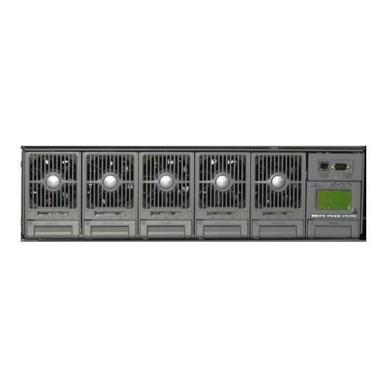
Control unit Rectifier shelf Rectifier cover Battery connection unit Battery shelf Door Figure 1-1 Outline There are three kinds of DC Power Systems, and their detail configurations are as shown in Table 1-1: ACTURA Flex 48330 Power System User Manual... -
Page 13: Table 1-1 Configurations Of Actura Flex 48330 Power System
Chapter 1 System Description Table 1-1 Configurations of Actura Flex 48330 Power System Cabinet dimension Configuration 2.0 % 0.6 % 0.6 m 2.0 % 0.6 % 0.4 m 0.7 % 0.6 % 0.4 m 3P+N/380V AC input with SPD 3P+N/380V AC input without SPD... -
Page 14: Components
The user can mount the rectifier shelf into cabinets with widths of 600mm and depths of 400mm. The rectifier shelf has a height of 3U (132.5mm). Figure 1-3 Rectifier shelf with rectifiers and CU ACTURA Flex 48330 Power System User Manual... -
Page 15: Table 1-2 Dimensions Of Rectifier Shelf
Connector board is a user interface board and has the functions below: 8-channel relay outputs 8-channel digital inputs One power source feed terminal (for digital inputs) 2-channel temperature sensor inputs 2-channel RS232 parallel connection outputs LLVD & BLVD bistable contactor driver circuits and outputs ACTURA Flex 48330 Power System User Manual... -
Page 16: Rectifier
The appearance and dimensions (unit: mm) of the rectifier are illustrated in the following figure. Figure 1-4 Dimensions Weight: ≤3.5kg Dimensions (H × W % D): 124.3mm % 84mm % 287mm The functions of the indicators in front panel are listed in Table 1-3. ACTURA Flex 48330 Power System User Manual... -
Page 17: Scu
The communication distance shall be less than 15m. If SCU communicates with MC through RS232, just connect SCU RS232 port to the RS232 port of MC. 2. Communication through MODEM or ES-MOD ACTURA Flex 48330 Power System User Manual... - Page 18 PLC can be set to “Disabled”. If PLC functions and alarm co-relation are enabled at the same time, the dry contact will act to activate an alarm when any alarm event occurs. ACTURA Flex 48330 Power System User Manual...
-
Page 19: Multi-Function Unit (Mfu)
LLVD contactor Shunt AC input terminals BLVD contactor Rectifier AC input MCB Battery MCB Battery -48V bus Low prior load bus Load MCB Prior load bus Figure 1-6 Outline and components of MFU ACTURA Flex 48330 Power System User Manual... -
Page 20: Battery Connection Unit (Bcu)
Controller. It shall be possible to combine the alarms from 2 BCUs to generate a single alarm in the controller. It shall also be possible to combine the alarm from the BCU with an ACTURA Flex 48330 Power System User Manual... -
Page 21: System Cabinet
This cabinet accommodates 1 % MFU, 1 % Rectifier Sub-racks and 1 % BCU. There shall be 3U available for the mounting of additional equipment such as DC/DC converters. The cabinet should not be installed any battery. ACTURA Flex 48330 Power System User Manual... -
Page 22: Chapter 2 Installation
Backup batteries and generator should be configured according to the actual power supply situation. The AC power supply system composed of AC mains and generator should adopt centralized power supply mode to supply power, while low ACTURA Flex 48330 Power System User Manual... -
Page 23: Site Survey
When the wiring distance is less than 30 meters, take 2.5A/mm of economical current density to calculate the sectional area of the AC cables. The sectional area of the DC load cables and battery cables should be calculated using the following formula: A=ΣI×L/K△U ACTURA Flex 48330 Power System User Manual... -
Page 24: Unpacking
5. The condition of the goods through visual inspection. For example, check if the cabinet is damaged, if the cabinet has regained moisture; shake gently the rectifiers and monitoring module to see if the parts and connections have been loosened during delivery. ACTURA Flex 48330 Power System User Manual... -
Page 25: Installation Procedures
The expansive pipes delivered with the power system are M10%55mm, therefore, use electric drill with drill bit Φ12 and depth 70mm to drill holes at the center points of the installation holes marked on the ground. To avoid being off-center, be careful ACTURA Flex 48330 Power System User Manual... -
Page 26: Figure 2-2 Installing Expansive Pipe
The cabinet fixation is illustrated in Figure 2-3. Tap bolt Plain washer Spring washer Cabinet base Ground Expansive pipe Figure 2-3 Fixing cabinet with Tap ACTURA Flex 48330 Power System User Manual... -
Page 27: External Electrical Connection Interface
AC Input Cable Figure 2-4 Cable mounted with H terminal After attaching the H terminal to the AC input cable, connect the AC input cable to the AC input terminals as shown in Figure 2-5: ACTURA Flex 48330 Power System User Manual... -
Page 28: Figure 2-5 Connection Of Input Terminals
There are 4 AC input terminals. For 3-phase AC power input, just connect the AC input cables as shown in Figure 2-7: L1 L2 L3 N AC input terminals Figure 2-7 Connection of 3-phase AC power input ACTURA Flex 48330 Power System User Manual... -
Page 29: Figure 2-8 Connection Of Single-Phase Ac Power Input
(including live lines, zero line), but input earth line can not be disconnected by any breaking device. It is recommended that the rated current of the AC input MCB is not less than 125A. ACTURA Flex 48330 Power System User Manual... -
Page 30: Connection Of Load Cables
H terminal to the cable, insert the cable into the wiring hole of the MCB, then tighten the screw to fix the copper core, as shown in Figure 2-11: Cable H terminal Figure 2-11 Cable connection to MCB ACTURA Flex 48330 Power System User Manual... -
Page 31: Connection Of Communication Cables
There is an Ethernet port and a DB9 RS232 port on the front panel. For the connection of communication cables, first connect the Ethernet port to the transmission equipment, and then connect the DB9 RS232 port to the Main Computer. ACTURA Flex 48330 Power System User Manual... -
Page 32: Layout Of Connector Board S6415X2
Chapter 2 Installation 2.3.4 Layout Of Connector Board S6415X2 Figure 2-13 Layout of connector board S6415X2 ACTURA Flex 48330 Power System User Manual... -
Page 33: Interface Definition Of Connector Board S6415X2
TXD232 Data Terminal Ready DTR232 J12, J18 Data Communication ground DGND Empty Request To Send RTS232 Empty Ethernet TX+ NETTX+ Ethernet TX- NETTX- Ethernet TR+ NETTR+ Empty Empty Ethernet TR- NETTR- 7~12 Empty ACTURA Flex 48330 Power System User Manual... -
Page 34: Connection Of Temperature Sensor Cables
S6415X2 board first, pass the RS232 terminal through the opening on the right side of the rectifier subrack and connect it with the J18 terminal on the S6415X2 board, then insert the S6415X2 board. ACTURA Flex 48330 Power System User Manual... -
Page 35: Connection With Dry Contacts
2. Place the battery on the level and push it inward until the battery is blocked; 3. Connect the positive and negative battery cable to the battery string. The cabinet with four battery strings installed is shown in Figure 2-15: ACTURA Flex 48330 Power System User Manual... -
Page 36: Battery Cable Connection
1) Batter Connection for Cabinet of 600 % 400 % 700(mm) The four left-most circuit breakers in the MFU connect to the negative battery cables (blue) respectively as shown in Figure 2-16. Another end of the negative ACTURA Flex 48330 Power System User Manual... -
Page 37: Figure 2-16 Connection Of Battery Cables
One end of positive battery cable is connected to the neutral bus of the DC power cabinet. Another end of the positive battery cable is connected to the positive terminal of the battery string in each level as shown in Figure 2-17. ACTURA Flex 48330 Power System User Manual... -
Page 38: Figure 2-18 Negative Battery Cables Connection In Bcu
Since the battery voltage decreases in discharge, hence the sectional area of the cable connecting the battery and the MFU or BCU should be relatively big to keep the voltage drop on the cable within 0.5V. ACTURA Flex 48330 Power System User Manual... -
Page 39: Parallel Connection Of Cabinets
SCU can display the alarm signals from these two BCUs. The user can connect the MFU to an additional extension MFU (only for additional load circuit breakers) through suitably rated cables. ACTURA Flex 48330 Power System User Manual... -
Page 40: Chapter 3 Startup
The voltage shall be within the rectifier Check the mains phase voltage. input voltage range (85Vac~290Vac). The cables shall be connected to their Check the connection of cables. correct terminals firmly. ACTURA Flex 48330 Power System User Manual... -
Page 41: Startup Process
After start up the DC Power System, following parameters need to be configured: Password, AC parameters, DC parameters, rectifier parameters, battery parameters, time and communication parameters. Refer to Chapter 5 on how to configure the parameters. ACTURA Flex 48330 Power System User Manual... -
Page 42: Chapter 4 Testing
BLVD management requirements, please reset the system parameters according to the actual situation, and record the new settings on the parameter card. ACTURA Flex 48330 Power System User Manual... -
Page 43: Battery Breaker Test
1. Close the load MCB, DC power should be fed to the load; 2. Adjust the system parameters through the SCU, and make sure that the information viewing and output control functions are normal. ACTURA Flex 48330 Power System User Manual... -
Page 44: Chapter 5 Operating Scu
“ to move the curso left or “ ” and At the first page of system information, use right, or “ ” and “ ” to set each digit. “ ” these two keys to change LCD contrast. ACTURA Flex 48330 Power System User Manual... -
Page 45: Operation Procedures
3. The first system information page appears 2004-09-16 53.5V 125 A System: No alarm Auto /BC The system information is shown in many pages. You can repeatedly press “ ” to view other system information pages in a cycle. ACTURA Flex 48330 Power System User Manual... -
Page 46: Querying System Status
Among which, the battery state include FC, temperature compensation, BC, Cyclic Boost, test, short test and scheduled test. The current time are displayed in two pages shifting at the interval of 2s. One page shows year, month and date, the ACTURA Flex 48330 Power System User Manual... -
Page 47: Other System Information Screen
“Not connected”, and no actual capacity will be displayed. Note There is only one current shunt in the system, that is “shunt 1”. ACTURA Flex 48330 Power System User Manual... - Page 48 AC information page There is no AC data acquisition board in ACTURA Flex 48330 Power System,so the configuration of “AC Input” can only be set to “None”. BC prompt and temperature information page...
-
Page 49: Querying Rectifier Status
At most 48 pieces of rectifier’s information can be displayed. If the rectifier does not exist, there will be no information. If the rectifier communication is interrupted, the information will be displayed in high light. ACTURA Flex 48330 Power System User Manual... -
Page 50: Querying Alarms And Setting Alarm Plans
” to select the “Active Alarm”, as shown in the above figure, and press “ENT” to confirm. 1) If there is no active alarm, “Active Alarm: None” will be displayed Active Alarm! None ACTURA Flex 48330 Power System User Manual... -
Page 51: Query Alarm History
5.5.2 Query Alarm History 1. At any system information page, press “ENT” to enter the main menu 2. Press “ ” or “ ” to select the “Status” submenu, and press “ENT” to confirm. ACTURA Flex 48330 Power System User Manual... - Page 52 If it is a rectifier that raised the alarm, the ID of that rectifier will be displayed. 4. At any Alarm History information page, press “ESC” repeatedly to return to the higher-level menus. ACTURA Flex 48330 Power System User Manual...
-
Page 53: Alarm Type Table
“Temp Major None point Threshold: Over Temp” Battery temperature is higher than High temperature alarm Batt Temp High the set value of parameter “Temp Observation None point Threshold: High Temp” ACTURA Flex 48330 Power System User Manual... - Page 54 Critical None disconnection or alarm circuit faulty Over-load, short circuit, manual Batt2 Failure Critical None disconnection or alarm circuit faulty Over-load, short circuit, manual Batt3 Failure Critical None disconnection or alarm circuit faulty ACTURA Flex 48330 Power System User Manual...
- Page 55 The difference is more than 1V The pre-set system maintenance System Maintain Observation None time is due Alarms sent to the host are blocked, Alarm Block No alarm None valid in EEM-M protocol ACTURA Flex 48330 Power System User Manual...
-
Page 56: Changing Audible/Visual Alarm And Alarm Call Back Plan
C = A (Status) * B (Status) C: The dry contract serial No. of the corresponding output. Range: 1 ~ 8. A, B: The input alarm type. Status: Whether the alarm has been raised. ACTURA Flex 48330 Power System User Manual... -
Page 57: Table 5-5 Optional Alarm Types
Temperature detection 2 Monitoring module in operation Used for monitoring module power off Module self test Manual mode Non-FC state of battery Battery discharge Current imbalance Battery short test Battery test alarm LLVD ACTURA Flex 48330 Power System User Manual... -
Page 58: Set The Alarm Names Through Plc Function
4 is 0-3. If the setting is 0, the logic is “AND”; If the setting is “1”, the logic is “NOT”; If the setting is “2”, the logic is “OR”; and if the setting is “3”, the logic is “AND”. ACTURA Flex 48330 Power System User Manual... -
Page 59: Table 5-6 Logic Matrix Used For Configuring 8 Dry Contacts
Table 5-8 PLC SN and Alarm Alarm Remark description Alarm Block Disabled for China Market, Enabled for rest of world Load 1 Failure Load 2 Failure Load 3 Failure Load 4 Failure Load 5 Failure ACTURA Flex 48330 Power System User Manual... - Page 60 Enabled when a battery shunt is connected in DC Power System Batt1 Fuse Batt2 Fuse Batt3 Fuse Batt4 Fuse Measured Temp1 Measured Temp2 SCU Working For LVD Self-detect Error Manual Mode Non-FC Status Batt Discharge Curr Imbalance Only for China Market ACTURA Flex 48330 Power System User Manual...
-
Page 61: Maintenance
You cannot enter the system Maintenance menu if the “Battery Management” is set to “Auto”. 3. Press “ENT” and input the correct operation password. Press “ENT” again to enter the “Maintenance” menu. Enter Password: 123456 ACTURA Flex 48330 Power System User Manual... - Page 62 ”RectTrim”: Range: 42V ~ 58V. It can be used to improve the current sharing among rectifiers. Note that the value of this parameter cannot exceed the over-voltage alarm point, or the parameter will be invalid. ”RectLimit”: Range: 10% ~ 121%. ACTURA Flex 48330 Power System User Manual...
-
Page 63: Setting System Parameters
5.7.1 Parameter Setting Method 1. At any system information page, press “ENT” to enter the main menu. MAIN MENU status Maintenance Settings ACTURA Flex 48330 Power System User Manual... -
Page 64: Table 5-9 Password Levels And Authorities
Among which, the battery parameters are divided into 5 kinds: basic, BLVD, charging management, battery test, temperature coefficient, and they are displayed in two pages, as shown below: ACTURA Flex 48330 Power System User Manual... -
Page 65: Batt. Selection
Press “ENT” to confirm afterwards. 2. If setting parameter “System Type” does not require setting the battery shunt coefficient, the second page of the basic battery settings is as follows: Batt Shunt1: Batt Shunt2: ACTURA Flex 48330 Power System User Manual... -
Page 66: Lvd Parameter Description
BLVD means the monitoring module opens the BLVD contactor. In this way, the battery will stop powering the load, preventing over-discharge. 2. There are 3 related pages, as shown below: ACTURA Flex 48330 Power System User Manual... -
Page 67: Charging Management Parameters
BLVD Time 600min reaches the preset “BLVD Time”, it will disconnect the battery 5.7.4 Charging Management Parameters 1. There are 6 related pages, as shown below: Float: 53.5 Boost: 56.4 Limit: 0.100C10 Over: 0.300c10 ACTURA Flex 48330 Power System User Manual... - Page 68 Press “ENT” to confirm and save. Note Generally you do not need to set the management value. The defaults will do. 2. The charging management parameter value description is listed below: ACTURA Flex 48330 Power System User Manual...
-
Page 69: Table 5-12 Charging Management Parameter Value Description
"To BC Current" Battery capacity smaller than "To BC Capacity" Charge current Constant BC smaller than time-up "Constant BC Constant Curr" BC time longer than "BC LVD Time" Abnormal situation Figure 5-2 BC/FC switchover diagram ACTURA Flex 48330 Power System User Manual... -
Page 70: Battery Test Parameters
9999A Use “ ” or “ ” to select one page or one of the parameters, and “ ” or “ ” to select the parameter value. Press “ENT” to confirm and save. ACTURA Flex 48330 Power System User Manual... -
Page 71: Table 5-13 Value Description Of The Battery Test Parameters
"Test End Cap" is Battery Manually start battery voltage Battery reached discharges battery test Auto-management Rectifier hot "Test End Time" is standby reached Figure 5-3 Schematic diagram of the test function ACTURA Flex 48330 Power System User Manual... -
Page 72: Temperature Compensation Coefficient Parameters
36mV/°C Comp 500mV/°C and “DC Voltage High”, the monitoring module will not do for 24V temperature compensation to the battery FC voltage. system. Set this parameter according to the actual battery technical parameters ACTURA Flex 48330 Power System User Manual... -
Page 73: Ac Settings
Set this parameter according to the actual situation. In a system with an AC Single AC Input sampling board, you can only select “Single Phase” or “3-phase”; in a system Phase, system without an AC sampling board, you can select only “None”. None type ACTURA Flex 48330 Power System User Manual... -
Page 74: Dc Setting
Set according to the system actual situation Dependent on system In the system with a load shunt, this parameter can be set only when Shunt Coeff type the parameter “Shunt” (as a system type) is set to “Set”. ACTURA Flex 48330 Power System User Manual... -
Page 75: Rect Settings
“HVSD Time”. If the rectifier’s output voltage is normal within the delay, the rectifier is regarded normal; otherwise, the rectifier will be locked out and auto-restart function will be disabled ACTURA Flex 48330 Power System User Manual... -
Page 76: System Settings
Press “ENT” to confirm. 2. For the operator level password (by default: 654321) or administrator level password (by default: 640275), you can see the following pages, besides the pages above, as shown below: ACTURA Flex 48330 Power System User Manual... - Page 77 ” to move the cursor left or right. Press “ENT” to confirm. You should input the same number twice to complete the setting. 4. The value description of the parameters is listed below: ACTURA Flex 48330 Power System User Manual...
-
Page 78: Table 5-18 Value Description Of System Settings
Y, N parameters will be restored to defaults. Alarms may parameter be raised for the defaults may fail to meet the actual situation. Set the parameters according to the actual situation then. ACTURA Flex 48330 Power System User Manual... -
Page 79: Figure 5-4 System Model Description
5. The model description is shown below: NONE No AC data acquisition board System shunt coefficient: 100/300/500/SET Rectifier rated output current: 15A/30A/50A/75A/100A Rectifier rated output voltage: 48V/24V Figure 5-4 System model description ACTURA Flex 48330 Power System User Manual... -
Page 80: Alarm Settings
PS48600-3/2900, Double AC inputs, Auto Switchover 48V/50A/500/AUTO Note SCU can monitor multiple power systems made by Emerson. If the system type is not set correctly, unpredictable faults may occur. 5.7.11 Alarm Settings 1. The first page of the setting interface is show below:... -
Page 81: Table 5-20 Value Description Of Alarm Settings
DIs Clear His Alarm Y, N “Y”: Delete historical alarms “Y”: The active alarms will not be sent to the host (valid in Block Alarm Y, N EEM protocol) ACTURA Flex 48330 Power System User Manual... -
Page 82: Chapter 6 Routine Maintenance
MFU to disconnect the power to the loads. 2. MFU short-circuit When MFU short-circuit occurs, disconnect the AC power supply, isolate the batteries from the system, and then use battery or rectifier to directly supply power to load. ACTURA Flex 48330 Power System User Manual... -
Page 83: Cover Plates
(54V in a 48V DC power system at reference temperature). If it deviates, check your system to see that the setting is correct and that the temperature compensation is correct. Unit voltage ACTURA Flex 48330 Power System User Manual... -
Page 84: Replacement
DC power system. For instance, in an environment where the mean temperature is 35°C, it is necessary to replace the battery every 5-year operation. ACTURA Flex 48330 Power System User Manual... -
Page 85: Chapter 7 Troubleshooting
Replace the fan 2. Rectifier Current Sharing Unbalanced When multiple rectifiers are in parallel connection and the unbalance of current sharing among them is bigger than 3%, check if the communication cables are correctly connected. ACTURA Flex 48330 Power System User Manual... -
Page 86: Mains Failure
Meanwhile, communication stations should have adequate human and material resources and work out effective countermeasures to cope with these disasters. They should also have emergency management regulations and serious accidents emergency plans. ACTURA Flex 48330 Power System User Manual... -
Page 87: Appendix 1 System Technical Parameters
90%RH, apply a test voltage of 500Vdc. The Others insulation resistances between AC circuit and earth, between Insulation resistance DC circuit and earth, or between AC and DC circuits are no less than 10M Ω ACTURA Flex 48330 Power System User Manual... - Page 88 600 (W) % 600 (D) 600 (W) % 400 600 (W) % 400 (D) Size (mm) % 2000 (H) (D) % 2000 (H) % 700 (H) Mechanica <135kg (without <125kg (without <60kg (without Weight rectifiers) rectifiers) rectifiers) ACTURA Flex 48330 Power System User Manual...
-
Page 89: Appendix 2 Engineering Design Diagram
Appendix 2 Engineering Design Diagram Appendix 2 Engineering Design Diagram Appendix 2.1 Engineering Design Diagram For 2000mm%600mm%600mm Cabinet ACTURA Flex 48330 Power System User Manual... -
Page 90: Appendix 2.2 Engineering Design Diagram For 2000Mm%600Mm%400Mm Cabinet
Appendix 2 Engineering Design Diagram Appendix 2.2 Engineering Design Diagram For 2000mm%600mm%400mm Cabinet ACTURA Flex 48330 Power System User Manual... -
Page 91: Appendix 2.3 Engineering Design Diagram For 700Mm%600Mm%400Mm Cabinet
1 big wire connectors, (cable section 25mm 4 M8blots, 6 big wire connectors, (cable section 25mm Positive bus bar DC Power 23 small wire connectors, (cable section 16mm distribution H cable terminals (cable section 25mm Output route ACTURA Flex 48330 Power System User Manual... -
Page 92: Appendix 3 System Circuit Diagram
Appendix 3 System Circuit Diagram Appendix 3 System Circuit Diagram Appendix 3.1 System Electric Schematic Diagram ACTURA Flex 48330 Power System User Manual... -
Page 93: Appendix 3.2 System Wiring Diagram
Appendix 3 System Circuit Diagram Appendix 3.2 System Wiring Diagram ACTURA Flex 48330 Power System User Manual... -
Page 94: Appendix 3.3 Mfu Electric Wiring Diagram
Appendix 3 System Circuit Diagram Appendix 3.3 MFU Electric Wiring Diagram ACTURA Flex 48330 Power System User Manual... -
Page 95: Appendix 3.4 Bcu Electric Wiring Diagram
Appendix 3 System Circuit Diagram Appendix 3.4 BCU Electric Wiring Diagram ACTURA Flex 48330 Power System User Manual... -
Page 96: Appendix 4 Glossary
Load Low Voltage Disconnection Low Voltage Disconnection Ph-A Phase A Password Rect Rectifier Shunt coeff Shunt Coefficient Surge Protection Device SW Version Software Version System Temp Temperature Temp Comp Temperature Compensation Volt Voltage ACTURA Flex 48330 Power System User Manual...
Need help?
Do you have a question about the ACTURA Flex 48330 and is the answer not in the manual?
Questions and answers