Table of Contents
Advertisement
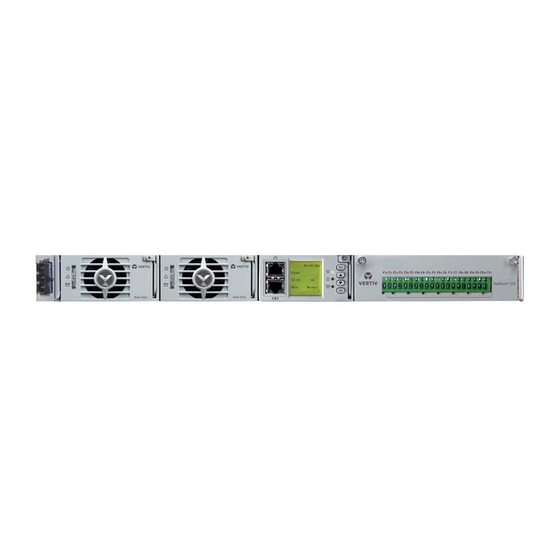
NetSure 211 C45 Embedded Power
Supply System
User Manual
Version
V1.0
Revision date September 15, 2009
BOM
31012178
Emerson Network Power provides customers with
technical support. Users may contact the nearest
Emerson local sales office or service center.
Copyright © 2009 by Emerson Network Power
Co., Ltd.
All rights reserved. The contents in this document
are subject to change without notice.
Emerson Network Power Co., Ltd.
Address: No.1 Kefa Rd., Science & Industry Park,
Nanshan District 518057, Shenzhen China
Homepage: www.emersonnetworkpower.com.cn
E-mail: support@emersonnetwork.com.cn
Advertisement
Table of Contents

Related Manuals for Emerson NetSure 211 C45


Summary of Contents for Emerson NetSure 211 C45
- Page 1 Revision date September 15, 2009 31012178 Emerson Network Power provides customers with technical support. Users may contact the nearest Emerson local sales office or service center. Copyright © 2009 by Emerson Network Power Co., Ltd. All rights reserved. The contents in this document are subject to change without notice.
-
Page 2: Safety Precautions
When operating Emerson products, the operation personnel must observe the safety rules in the industry, the general safety points and special safety instructions specified in this book. - Page 3 IV. ESD Note The static electricity generated by the human body will damage the static sensitive elements on PCBs, such as large-scale ICs. Before touching any plug-in board, PCB or IC chip, ESD wrist strap must be worn to prevent body static from damaging the sensitive components.
- Page 4 Others I. Safety Note Noti ce Warning When replacing power input fuses of monitoring module and power distribution units, use the same type fuses to meet the safety requirement. II. Sharp object Warning When moving equipment by hand, wear protective gloves to avoid injury by sharp object. III.
-
Page 5: Table Of Contents
Contents Chapter 1 Overview ................................1 1.1 Model Description ..............................1 1.2 Composition And Configuration ..........................1 1.3 Features ................................2 Chapter 2 Installation Instruction ............................3 2.1 Safety Regulations ..............................3 2.2 Preparation ................................3 2.3 Mechanical Installation ............................5 2.4 Electrical Installation ............................. -
Page 7: Chapter 1 Overview
Brand name of the system Figure 1-1 Model description 1.2 Composition And Configuration NetSure 211 C45 power supply system has two models, NetSure 211 C45-S1 and NetSure 211 C45-S2. The appearances of the two systems are shown in Figure 1-2 and Figure 1-3. Rectifier... -
Page 8: Features
The monitoring module is of network design. With an RS232 port, Ethernet, dry contacts and other communication ports provided, flexible networking is enabled to achieve remote monitoring and unattendance. The system has complete fault protection and fault alarm functions. NetSure 211 C45 Embedded Power Supply System User Manual... -
Page 9: Chapter 2 Installation Instruction
The equipment should be unpacked and inspected after it arrives at the installation site. The inspection shall be done by representatives of both the user and Emerson Network Power Co., Ltd. To inspect the equipment, you should open the packing case, take out the packing list and check against the packing list that the equipment is correct and complete. - Page 10 1.5mm . The earth terminal is one M5 bolt. 2. Cable specifications of NetSure 211 C45-S2 power supply system It is recommended to use the RVVZ cables as AC cables. The cable should reach at least +70°C temperature durability. Select the AC cable Cross-Sectional Area (CSA) according to Table 2-4.
-
Page 11: Mechanical Installation
Fix the brackets on the power supply subrack with bolts. Users can choose proper installation position according to actual instance. 2. Install the power supply subrack. Fix the subrack in the cabinet with fixing screws. The installation dimensions are shown in Figure 2-2 and Figure 2-3. NetSure 211 C45 Embedded Power Supply System User Manual... - Page 12 Chapter 2 Installation Instruction 465.00 482.00 Figure 2-2 Installation dimensions of NetSure 211 C45-S1 power supply system (unit: mm) 465.00 482.00 Figure 2-3 Installation dimensions of NetSure 211 C45-S2 power supply system (unit: mm) NetSure 211 C45 Embedded Power Supply System User Manual...
-
Page 13: Electrical Installation
4. Be careful not to reversely connect the battery. Otherwise, both the battery and the system will be damaged! 1. Cable connection of NetSure 211 C45-S1 power supply system Before connecting AC input cables, remove the back cover of the system, as shown in Figure 2-4. -
Page 14: Connecting Signal Cables
Battery socket Lead the AC input cables through the AC cable entry hole, and reinstall the back cover. 1. Cable connection of NetSure 211 C45-S2 power supply system The positions of the connection terminals are shown in Figure 2-7. Load connection terminal... - Page 15 Chapter 2 Installation Instruction 2. Cable connection of NetSure 211 C45-S2 power supply system The position of the dry contact and temperature probe connection terminal is shown in Figure 2-7, and the screen print is shown in Figure 2-9. A amplified view...
- Page 16 The default associations of the relays are: critical alarm associating with DO1, and major alarm associating with DO2. A amplified view NetSure 211 C45 Embedded Power Supply System User Manual...
-
Page 17: Chapter 3 Installation Testing
Check the system voltage and busbar polarity with a voltmeter. The voltage difference between the measured value and displayed value should be less than ± 0.3V Start and stop each rectifier by inserting and unplugging the rectifiers. Check their output voltages NetSure 211 C45 Embedded Power Supply System User Manual... -
Page 18: Basic Settings
The battery protection contactor should be open, and the ‘BLVD’ alarm should be displayed at the monitoring module Note: The monitoring module will give alarms approximately 10s after the alarms are triggered. Enter main menu Operation to view the alarm information NetSure 211 C45 Embedded Power Supply System User Manual... -
Page 19: Final Steps
If any defect is found in this equipment, inform the personnel responsible for the contract. If repairing is needed, please fill in the FAILURE REPORT and send the report together with the defective unit to the repairing center for fault analysis. NetSure 211 C45 Embedded Power Supply System User Manual... -
Page 20: Chapter 4 Alarm Handling
Alarm/ Batt it. Or check the voltage at the alarm fuse. If the voltage is almost 0V, the fuse is normal. Fuse Alarm Otherwise, the alarm loop is faulty. Please contact Emerson NetSure 211 C45 Embedded Power Supply System User Manual... -
Page 21: Handling Rectifier Fault
Ambient temperature too Decrease the ambient temperature or remove due to: high or the inlet too close to the heat source a heat source NetSure 211 C45 Embedded Power Supply System User Manual... - Page 22 3. Press the rectifier handle to pop it out. Pull out the faulty rectifier from the rack by grabbing its handle. Be careful with the rectifier just pulled out from the system, as it could be very hot due to long-term operation. Do not let it slip away and get damaged. NetSure 211 C45 Embedded Power Supply System User Manual...
- Page 23 If the new rectifier passes all the above tests, the replacement is a success. 6. Push the handle back into the front panel to lock the rectifier. 7. Fix the fixing screw of the handle of the rectifier with a Phillips screwdriver. NetSure 211 C45 Embedded Power Supply System User Manual...
-
Page 24: Appendix 1 Technical Data
100% rated current Rectifier Input voltage: 176Vac ~ 290Vac, rectifier max. output power: 50% rated power, Derate by input (45°C) 1000W Input voltage: 90Vac ~ 176Vac, rectifier output power: linear derating power NetSure 211 C45 Embedded Power Supply System User Manual... - Page 25 1min, with leakage current not bigger than 10mA ROHS Compliant with R5 standard 437 × 289 × 88 (for NetSure 211 C45-S2 power supply system, the size does not Size (W ×D System include MCB or connection terminal at the back) ×H) (mm)
-
Page 26: Appendix 2 Wiring Diagram
(L2) 10-10 8-H52 J207 10-11 4-X1-25 10-12 4-X1-23 J217 D C - SA411X2 R ec1 R ec2 (L1) (L2) J218 D C + Figure 1 Wiring diagram of Netsure 211 C45-S1 NetSure 211 C45 Embedded Power Supply System User Manual... - Page 27 3-X1-4/4-35 4-47/4-49 10-4 10-2 13-BAT+ 7-PE 6-J211 Load& connector DI/DO connector 12-DO2 COM 12-DI2- 12-DO2 NO 12-DI2+ 12-DO1 COM 12-DI1- 12-DO1 NO 12-DI1+ Figure 2 Wiring diagram of Netsure 211 C45-S2 NetSure 211 C45 Embedded Power Supply System User Manual...
-
Page 28: Appendix 3 Glossary
Low Voltage Disconnection Miniature Circuit Breaker Ph-A Phase A Password Rect Rectifier Shunt coeff Shunt Coefficient Surge Protection Device SW Version Software Version System Temp Temperature Temp Comp Temperature Compensation Volt Voltage NetSure 211 C45 Embedded Power Supply System User Manual...
Need help?
Do you have a question about the NetSure 211 C45 and is the answer not in the manual?
Questions and answers