Table of Contents
Advertisement
Quick Links
NetSure 501 A50, NetSure 501 AA0, NetSure 701 A51
19-Inch Subrack Power Supply System
User Manual
Version
Revision date
BOM
Emerson Network Power provides customers with technical support. Users may contact the nearest
Emerson local sales office or service center.
Copyright © 2008 by Emerson Network Power Co., Ltd.
All rights reserved. The contents in this document are subject to change without notice.
Emerson Network Power Co., Ltd.
Address: No.1 Kefa Rd., Science & Industry Park, Nanshan District 518057, Shenzhen China
Homepage: www.emersonnetworkpower.com.cn
E-mail: support@emersonnetwork.com.cn
V1.0
June 13, 2008
31011680
Advertisement
Table of Contents

Related Manuals for Emerson NetSure 501 A50


Summary of Contents for Emerson NetSure 501 A50
- Page 1 Revision date June 13, 2008 31011680 Emerson Network Power provides customers with technical support. Users may contact the nearest Emerson local sales office or service center. Copyright © 2008 by Emerson Network Power Co., Ltd. All rights reserved. The contents in this document are subject to change without notice.
- Page 2 When operating Emerson products, the safety rules in the industry, the general safety points and special safety instructions specified in this book must be strictly observed.
- Page 3 Notice Notice The static electricity generated by the human body will damage the static sensitive elements on PCBs, such as large-scale ICs. Before touching any plug-in board, PCB or IC chip, ESD wrist strap must be worn to prevent body static from damaging the sensitive components.
- Page 4 The method of disabling BLVD is: Set “BLVD Enable” item of the monitoring module to “N”. Refer to 4.7.3LVD Parameter Description, 5.5.2Battery Management Parameters or 6.7.3Battery Settings for setting method. Noti c e Notice The advantage of enabling BLVD is protecting the batteries from over-discharge when the battery voltage is low. The disadvantage of enabling BLVD is that when the battery voltage drops down to a certain value, all the loads (including non- priority loads and priority loads) will be cut off due to battery disconnection.
-
Page 5: Table Of Contents
Contents Chapter 1 Overview................................1 1.1 Model Information..............................1 1.2 Composition And Configuration..........................1 1.3 Features................................. 3 Chapter 2 Installation Instruction............................4 2.1 Safety Regulations..............................4 2.2 Preparation................................4 2.3 Mechanical Installation............................5 2.4 Electrical Installation............................... 6 2.4.1 Connecting Power Cables........................... 6 2.4.2 Connecting Signal Cables........................... - Page 6 4.7.7 AC Settings............................... 30 4.7.8 DC Settings............................... 31 4.7.9 Rectifier Settings............................31 4.7.10 System Settings............................32 4.7.11 Alarm Settings............................34 Chapter 5 Use Of Monitoring Module M800D........................36 5.1 Operation Panel..............................36 5.2 Use Of The Operation Panel..........................37 5.2.1 Main Screen.............................. 37 5.2.2 Main Menu..............................
- Page 7 6.5.2 Querying Alarm History..........................87 6.5.3 Changing Audio/Video Alarm And Alarm Callback..................87 6.5.4 Change Alarm Types Of Dry Contacts......................88 6.5.5 Programmable Setting On The Dry Contact Output Alarm Type...............88 6.6 Maintenance................................. 89 6.7 Setting System Parameters..........................90 6.7.1 Parameter Setting Method........................90 6.7.2 Alarm Settings............................
-
Page 8: Chapter 1 Overview
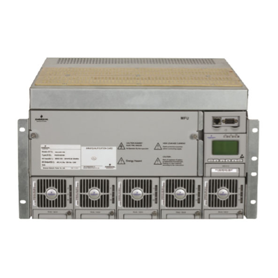
This chapter introduces model description, composition and configuration, and features. The “system” in this manual refers to the PS48150-3B/1800 (NetSure 501 A50) (abbreviated as “NetSure 501 A50”), PS48300-3C/1800 (NetSure 501 AA0) (abbreviated as “NetSure 501 AA0”) and PS48300-3A/3200 (NetSure 701 A51) &... - Page 9 Dummy plate Rectifier Figure 1.4 NetSure 701 A51 (PS48300-3A/3200-X2) system structure System configuration The configurations of the power supply system are described in Table 1-1. NetSure 501 A50, NetSure 501 AA0, NetSure 701 A51 19-Inch Subrack Power Supply System User Manual...
-
Page 10: Features
The rectifier uses the active Power Factor Compensation (PFC) technology, raising the power factor to 0.99 Wide AC input voltage range: 85V ~ 290V (NetSure 701 A51) or 85Vac ~ 300Vac (NetSure 501 A50 & NetSure 501 AA0) The rectifier uses soft switching technology, raising the system efficiency to 89% (R48-1800)/ 90% (R48-3200) ... -
Page 11: Chapter 2 Installation Instruction
The CSA of DC cable depends on the current flowing through the cable and the allowable voltage drop. To select the battery cable CSA, see Table 2-1. Select the DC load cable CSA according to the Table 2-2: NetSure 501 A50, NetSure 501 AA0, NetSure 701 A51 19-Inch Subrack Power Supply System User Manual... -
Page 12: Mechanical Installation
Figure 2-4 with a Phillips screwdriver. Figure 1.1 Installation size of NetSure 501 A50 (unit: mm) 466.8 Figure 1.2 Installation size of NetSure 501 AA0 (unit: mm) NetSure 501 A50, NetSure 501 AA0, NetSure 701 A51 19-Inch Subrack Power Supply System User Manual... -
Page 13: Electrical Installation
Feed all the cables into the subrack from top of the subrack. Take the NetSure 701 A51 power supply system as an example, the position of the connection terminals are shown in Figure 2-5. Connect the AC input cables to the AC input MCB. NetSure 501 A50, NetSure 501 AA0, NetSure 701 A51 19-Inch Subrack Power Supply System User Manual... -
Page 14: Connecting Signal Cables
S6415X2 user connector board cable connection Take the NetSure 501 A50 power supply system as an example, the position of the user connector board is shown in Figure 2-6. Two communication interfaces are located in the panel: Ethernet and RS232 interface. The power supply system can be connected to Ethernet through the Ethernet interface or connected to modem through RS232 interface. - Page 15 Relay output 5 normal close DO5_NC Relay output 6 normal close DO6_NC Relay output 5 common DO5_COM Relay output 6 common DO6_COM Relay output 5 normal open DO5_NO NetSure 501 A50, NetSure 501 AA0, NetSure 701 A51 19-Inch Subrack Power Supply System User Manual...
- Page 16 In the modem mode, the monitoring module will initialize modem upon power-on, reset or upon communication interruptions that last more than one hour. NetSure 501 A50, NetSure 501 AA0, NetSure 701 A51 19-Inch Subrack Power Supply System User Manual...
-
Page 17: Chapter 3 Installation Testing
For monitoring module parameter setting method, see 4.7Setting System Parameters if using M500D. 5.2.5Parameter Set if using M800D. See 5.7 Setting System Parameters if using M501D. NetSure 501 A50, NetSure 501 AA0, NetSure 701 A51 19-Inch Subrack Power Supply System User Manual... -
Page 18: Alarm Check And System Operation Status Check
1%. Check the number of the rectifier through the monitoring module. The number should be consistent with the actual number. NetSure 501 A50, NetSure 501 AA0, NetSure 701 A51 19-Inch Subrack Power Supply System User Manual... -
Page 19: Final Steps
If repairing is needed, please fill in the FAILURE REPORT and send the report together with the defective unit to the repairing center for fault analysis. NetSure 501 A50, NetSure 501 AA0, NetSure 701 A51 19-Inch Subrack Power Supply System User Manual... -
Page 20: Chapter 4 Use Of Monitoring Module M500D
As for those important parameters related to battery management, such as BLVD, you should be fully aware of their influence upon the system before you change their values. NetSure 501 A50, NetSure 501 AA0, NetSure 701 A51 19-Inch Subrack Power Supply System User Manual... - Page 21 The maintenance operation can be conducted only when the battery management mode is set to “Manual”. The maintenance includes battery FC, BC and test, load power off/on, battery power off/on and rectifier voltage trimming, current limit, switch control and resetting. NetSure 501 A50, NetSure 501 AA0, NetSure 701 A51 19-Inch Subrack Power Supply System User Manual...
-
Page 22: Querying System Status
Ah or remaining time, etc. The default is the percentage. NetSure 501 A50, NetSure 501 AA0, NetSure 701 A51 19-Inch Subrack Power Supply System User Manual... - Page 23 (see 4.7 for parameter setting). If the temperature sensor is not connected or is faulty, system will prompt invalid. Meanwhile, the 4 row will display “Check Temp Sensor”. NetSure 501 A50, NetSure 501 AA0, NetSure 701 A51 19-Inch Subrack Power Supply System User Manual...
-
Page 24: Querying Rectifier Status
2. Use “▲” or “▼” to select the “Status” submenu in the main menu and press “ENT” to confirm. STATUS Rectifiers Active Alarm Alarm History NetSure 501 A50, NetSure 501 AA0, NetSure 701 A51 19-Inch Subrack Power Supply System User Manual... -
Page 25: Querying Alarm History
1. At any system information page, press “ENT” to enter the main menu 2. Press “▲” or “▼” to select the “Status” submenu, and press “ENT” to confirm. STATUS Rectifiers Active Alarm Alarm History NetSure 501 A50, NetSure 501 AA0, NetSure 701 A51 19-Inch Subrack Power Supply System User Manual... -
Page 26: Alarm Type Table
DC Volt High#1 DC output voltage high Critical voltage alarm point DC output over- DC Volt High#2 DC output voltage very high Critical voltage alarm point NetSure 501 A50, NetSure 501 AA0, NetSure 701 A51 19-Inch Subrack Power Supply System User Manual... - Page 27 Alarm name can be defined by users. Whether Digital8 /LVD2 the alarm is triggered at high voltage level or low No alarm None Alarm voltage level can be configured NetSure 501 A50, NetSure 501 AA0, NetSure 701 A51 19-Inch Subrack Power Supply System User Manual...
-
Page 28: Changing Audible/Visual Alarm And Alarm Call Back Plan
You can choose to enter the “Maintenance” menu by using either the user, operator or administrator password, for in this menu, all users have the same authority. NetSure 501 A50, NetSure 501 AA0, NetSure 701 A51 19-Inch Subrack Power Supply System User Manual... -
Page 29: Setting System Parameters
Without any special needs, you only need to reset the battery group number and battery capacity, and accept the defaults for other parameters. NetSure 501 A50, NetSure 501 AA0, NetSure 701 A51 19-Inch Subrack Power Supply System User Manual... -
Page 30: Parameter Setting Method
Charge ▼ What follows is the description of the parameter functions and values by dividing them into 5 small categories and 5 big categories. NetSure 501 A50, NetSure 501 AA0, NetSure 701 A51 19-Inch Subrack Power Supply System User Manual... -
Page 31: Battery Selection
The total capacity of the battery strings connected to one battery shunt. Rated AH (rated 50 ~ 5000Ah 300Ah You should set this parameter according to the actual battery capacity) configuration NetSure 501 A50, NetSure 501 AA0, NetSure 701 A51 19-Inch Subrack Power Supply System User Manual... -
Page 32: Lvd Parameter Description
3 ~ 1,000 min BLVD Time 600min monitoring module will disconnect the load; when the discharge time reaches the preset “BLVD Time”, it will disconnect the battery NetSure 501 A50, NetSure 501 AA0, NetSure 701 A51 19-Inch Subrack Power Supply System User Manual... -
Page 33: Charging Management Parameters
Boost Limit 60 ~ 2880min 1080min reaches the “Boost Limit”, or abnormalities occur (such as AC failure, battery route faulty, and rectifier communication failure etc.) NetSure 501 A50, NetSure 501 AA0, NetSure 701 A51 19-Inch Subrack Power Supply System User Manual... -
Page 34: Battery Test Parameters
Use “▼” or “▲” to select one page or one of the parameters, and “◄” or “►” to select the parameter value. Press “ENT” to confirm and save. NetSure 501 A50, NetSure 501 AA0, NetSure 701 A51 19-Inch Subrack Power Supply System User Manual... -
Page 35: Temperature Compensation Coefficient Parameters
Ambient Temp 2: Battery ▼ 2. If the “Temperature1” or “Temperature2” is set to “Battery Temp”, you need to set the following parameters: NetSure 501 A50, NetSure 501 AA0, NetSure 701 A51 19-Inch Subrack Power Supply System User Manual... -
Page 36: Ac Settings
The monitoring module will raise an alarm when the alrm disorder, it is suggested to LowVolt 50V ~ 300V 180V AC input voltage is lower than the “LowVolt” use the default values NetSure 501 A50, NetSure 501 AA0, NetSure 701 A51 19-Inch Subrack Power Supply System User Manual... - Page 37 3-phase board, you can only select “Single Phase” or “3-phase”; in a system without an AC None sampling board, you can select only “None” NetSure 501 A50, NetSure 501 AA0, NetSure 701 A51 19-Inch Subrack Power Supply System User Manual...
-
Page 38: Dc Settings
That delay is set through the parameter “HVSD Time”. If the rectifier’s output voltage is normal NetSure 501 A50, NetSure 501 AA0, NetSure 701 A51 19-Inch Subrack Power Supply System User Manual... -
Page 39: System Settings
SW Ver : 1.0 1Hour Set Enable : Y You can change the value of the parameter “Change Password” and press “ENT” to confirm. NetSure 501 A50, NetSure 501 AA0, NetSure 701 A51 19-Inch Subrack Power Supply System User Manual... - Page 40 ”N”, you are not allowed to use the jumper, nor change any parameter except the battery management mode. The maintenance over the monitoring module will not be affected NetSure 501 A50, NetSure 501 AA0, NetSure 701 A51 19-Inch Subrack Power Supply System User Manual...
-
Page 41: Alarm Settings
Rectifier rated output voltage: 48V/24V Note Monitoring module M500D can monitor multiple power systems made by Emerson. If the system type is not set correctly, unpredictable faults may occur. 4.7.11 Alarm Settings 1. The first page of the setting interface is show below: ALARM SETTINGS Alarm Type... - Page 42 “Y”: Delete historical alarms Alarm Block Alarm Y, N “Y”: The active alarms will not be sent to the host (valid in EEM protocol) NetSure 501 A50, NetSure 501 AA0, NetSure 701 A51 19-Inch Subrack Power Supply System User Manual...
-
Page 43: Chapter 5 Use Of Monitoring Module M800D
Change the edit value of a parameter. In main screen, press ◄ or ► to change the value of a ► Right press ◄ or ► to adjust the contrast of LCD parameter NetSure 501 A50, NetSure 501 AA0, NetSure 701 A51 19-Inch Subrack Power Supply System User Manual... -
Page 44: Use Of The Operation Panel
In the screen of Main Menu, press ▲ or ▼ to select the sub-menu of “Running Info”, and press ENT to activate the menu to show the screen of “Running Info”: NetSure 501 A50, NetSure 501 AA0, NetSure 701 A51 19-Inch Subrack Power Supply System User Manual... - Page 45 If the equipment category has only one piece of equipment, the detailed information will only be displayed in a one- level menu. For example, the signals of DC distribution unit are only displayed in one level: NetSure 501 A50, NetSure 501 AA0, NetSure 701 A51 19-Inch Subrack Power Supply System User Manual...
- Page 46 In the screen of “Running Info”, press ▲ or ▼ to select the sub-menu of History Alarm and press ENT to activate the menu, the following screen pops up if the DC power has history alarms: NetSure 501 A50, NetSure 501 AA0, NetSure 701 A51 19-Inch Subrack Power Supply System User Manual...
-
Page 47: Maintain
In the preceding screen, select a rectifier, for example, select Rectifier1, and press ENT to display the detailed information (signals) of the rectifier: Second-level: Rect DC Ctrl Rect AC Ctrl Rect AC Ctrl Rect Reset Control Method: NetSure 501 A50, NetSure 501 AA0, NetSure 701 A51 19-Inch Subrack Power Supply System User Manual... -
Page 48: Parameter Set
In above screen, press ▲ or ▼ to select the menu of “Rect Group” and press ENT to view the settable parameters of the rectifier: For example: NetSure 501 A50, NetSure 501 AA0, NetSure 701 A51 19-Inch Subrack Power Supply System User Manual... - Page 49 Alarm Level M800D System Rect Group Rectifier Method of setting the alarm level: NetSure 501 A50, NetSure 501 AA0, NetSure 701 A51 19-Inch Subrack Power Supply System User Manual...
- Page 50 M800D supports 2 languages, one is English and another is the local language, which are configurable through above screen. LCD Time Zone support the selection from GMT-12:00 to GMT+13:00. User can select the language in the preceding screen. NetSure 501 A50, NetSure 501 AA0, NetSure 701 A51 19-Inch Subrack Power Supply System User Manual...
-
Page 51: Access M800D Through Web
To log in M800D, double-click the icon of IE to run the software, click the menus of ToolsInternet Options and then click the button “Connections” to pop up the following screen: NetSure 501 A50, NetSure 501 AA0, NetSure 701 A51 19-Inch Subrack Power Supply System User Manual... - Page 52 If the M800D is connected to Internet and the user computer is connected to the intranet, the user cannot disable the proxy, otherwise he cannot access the M800D. NetSure 501 A50, NetSure 501 AA0, NetSure 701 A51 19-Inch Subrack Power Supply System User Manual...
-
Page 53: Homepage Introduction
M800D, and the homepage screen as shown in Figure 4-4 pops up. 5.3.3 Homepage Introduction The homepage screen is shown in Figure 4-5. NetSure 501 A50, NetSure 501 AA0, NetSure 701 A51 19-Inch Subrack Power Supply System User Manual... -
Page 54: Device Explore
Data browse, control and parameter setting of rectifier 1. Rectifier group In the screen shown in Figure 4-6, click “RectifierGroup”, following screen pops up: NetSure 501 A50, NetSure 501 AA0, NetSure 701 A51 19-Inch Subrack Power Supply System User Manual... - Page 55 “Full Speed” and click “Set” to make the rectifier fan run at full speed. The control command is effective for all the rectifiers. Pay attention that the “Control” button is only active when the M800D is in NetSure 501 A50, NetSure 501 AA0, NetSure 701 A51 19-Inch Subrack Power Supply System User Manual...
- Page 56 2. Single rectifier Click the submenu “Rectifier1” of “RectifierGroup”, following screen pops up as shown in Figure 4-9: NetSure 501 A50, NetSure 501 AA0, NetSure 701 A51 19-Inch Subrack Power Supply System User Manual...
- Page 57 Data browse, control and parameter setting of battery Click the icon in the left of “BatteryGroup”, all the sampled values of the battery group are displayed as shown in Figure 4-11. NetSure 501 A50, NetSure 501 AA0, NetSure 701 A51 19-Inch Subrack Power Supply System User Manual...
- Page 58 “Boost/Float charge control”, the user can set the “Float Charge” to “Boost Charge”, and click the button “set” to make the setting become effective. Click the button “setting” to view setting signals of the battery as shown in Figure 4-13. NetSure 501 A50, NetSure 501 AA0, NetSure 701 A51 19-Inch Subrack Power Supply System User Manual...
- Page 59 “Very High Temperature Limit”, the user can set the “temperature limit” from “36.00” to “38.00”, and click the button “set” to make the setting become effective. Click the submenu of “Battery1”, the following screen pops up: NetSure 501 A50, NetSure 501 AA0, NetSure 701 A51 19-Inch Subrack Power Supply System User Manual...
- Page 60 Figure 1.10 SM Battery sample signal Figure 4-15 shows the sampled values of SM battery 1. Click the button [Setting], to configure the battery parameters. NetSure 501 A50, NetSure 501 AA0, NetSure 701 A51 19-Inch Subrack Power Supply System User Manual...
- Page 61 Click the “Control” button to perform LVD control, for example, the user can set “LVD1 control” to “on” or “off” as shown in the following Figure: Figure 1.12 LVD control NetSure 501 A50, NetSure 501 AA0, NetSure 701 A51 19-Inch Subrack Power Supply System User Manual...
-
Page 62: Alarms
In any screen, click the icon “ ” located in the middle bottom part of the screen to pop up the alarm screen as ▼ ▼ shown below: NetSure 501 A50, NetSure 501 AA0, NetSure 701 A51 19-Inch Subrack Power Supply System User Manual... - Page 63 The major alarm is displayed in pink color and the critical alarm is displayed in red color. NetSure 501 A50, NetSure 501 AA0, NetSure 701 A51 19-Inch Subrack Power Supply System User Manual...
-
Page 64: Settings
5.3.6 Settings Click the icon in the left of “SETTINGS”, and then click the sub-menu of “Network configuration”, following screen pops up: NetSure 501 A50, NetSure 501 AA0, NetSure 701 A51 19-Inch Subrack Power Supply System User Manual... - Page 65 After modifying the IP address, be sure to re-log in the M800D with the new IP address. Click the sub-menu of “NMS Configure”, following screen pops up: Figure 1.2 NMS configuration NetSure 501 A50, NetSure 501 AA0, NetSure 701 A51 19-Inch Subrack Power Supply System User Manual...
- Page 66 In the screen shown in Figure 4-24, the user can configure the phone number and protocol for communication. Refer to the document of “ESR private configuration” for the meaning of each parameter. Click the sub-menu of “User information”, following screen pops up: NetSure 501 A50, NetSure 501 AA0, NetSure 701 A51 19-Inch Subrack Power Supply System User Manual...
- Page 67 A H/W switch is set that makes no writing of any kind possible to the product Click “Edit PLC Config” and then click “Add” button, the following screen shows up: NetSure 501 A50, NetSure 501 AA0, NetSure 701 A51 19-Inch Subrack Power Supply System User Manual...
- Page 68 Click “Add” to enable the PLC calculation, or click “Cancel” to cancel the PLC setting. Click “Edit GC PowerSplit”, the following screen shows up: NetSure 501 A50, NetSure 501 AA0, NetSure 701 A51 19-Inch Subrack Power Supply System User Manual...
- Page 69 “BOOST_CHARGE”: Figure 2.3 Edit the boost charge parameter Click the sub-menu of “Time synchronization” to calibrate the clock as shown in the screen below: NetSure 501 A50, NetSure 501 AA0, NetSure 701 A51 19-Inch Subrack Power Supply System User Manual...
-
Page 70: Maintenance
Click the menu of “Maintenance”, and then click “Upload/download” sub-menu to upload or download the files, as shown in the figure below: Figure 1.1 Upload/download screen 1 NetSure 501 A50, NetSure 501 AA0, NetSure 701 A51 19-Inch Subrack Power Supply System User Manual... - Page 71 “.tar” or “.tar.gz”. The M800D can also download the file with the filename of “MonitoringSolution.cfg”, except the above files, M800D cannot download other kind of files. NetSure 501 A50, NetSure 501 AA0, NetSure 701 A51 19-Inch Subrack Power Supply System User Manual...
- Page 72 In the screen shown in Figure 4-33, click “Save”, then the file will be placed in desktop. Soon, following screen pops up indicating that the file has been uploaded. Figure 1.5 Download complete Click the sub-menu of “Clear data”, following screen pops up: NetSure 501 A50, NetSure 501 AA0, NetSure 701 A51 19-Inch Subrack Power Supply System User Manual...
- Page 73 In the preceding screen, user can select “System Runtime log” to clear the log. In the same way, user can select “History battery test log” to clear the battery test log. Click the sub-menu of “Restore default”, following screen pops up: NetSure 501 A50, NetSure 501 AA0, NetSure 701 A51 19-Inch Subrack Power Supply System User Manual...
- Page 74 5 minutes before re-accessing the M800D through the Web. Click the sub-menu of “Site inventory”, following screen pops up: NetSure 501 A50, NetSure 501 AA0, NetSure 701 A51 19-Inch Subrack Power Supply System User Manual...
- Page 75 The screen shown in Figure 4-37 displays the product information which is sampled by M800D monitoring module. Click the sub-menu of “Get Setting Parameter”, following screen pops up: NetSure 501 A50, NetSure 501 AA0, NetSure 701 A51 19-Inch Subrack Power Supply System User Manual...
- Page 76 User can click the button of [Get Setting Parameter] to get the setting parameter of M800D monitoring module. Click the sub-menu of “Auto Configuration”, following screen pops up: NetSure 501 A50, NetSure 501 AA0, NetSure 701 A51 19-Inch Subrack Power Supply System User Manual...
- Page 77 User can click the button of [Auto Configuration] to start the process of auto configuration. Click the sub-menu of “Modify configure online”, and then click the button of “Modify M800D” to pop up following screen: NetSure 501 A50, NetSure 501 AA0, NetSure 701 A51 19-Inch Subrack Power Supply System User Manual...
- Page 78 In the screen shown in Figure 4-41, user can modify the device name. All entering the new device name, click “Set” to validate the change. NetSure 501 A50, NetSure 501 AA0, NetSure 701 A51 19-Inch Subrack Power Supply System User Manual...
-
Page 79: Query
User can modify the signal name in the screen shown in Figure 4-42. After the entering the new signal name, click “Set” to validate the change. 5.3.8 Query Click the menu of “Query”, and then click “History data” following screen pops up: NetSure 501 A50, NetSure 501 AA0, NetSure 701 A51 19-Inch Subrack Power Supply System User Manual... - Page 80 [Query] to query the data during this period. Figure 1.2 Query history data Click the button “Log” to pop up the following screen: NetSure 501 A50, NetSure 501 AA0, NetSure 701 A51 19-Inch Subrack Power Supply System User Manual...
- Page 81 June 29, 2005 will be displayed as shown in Figure 4-46. Figure 1.4 Control log Click the button “Battery test data”, and the following screen pops up: NetSure 501 A50, NetSure 501 AA0, NetSure 701 A51 19-Inch Subrack Power Supply System User Manual...
-
Page 82: Access M800D Through Nms
The contents of MIB supported by M800D SNMP agent, and the OID are listed in Table 4-4. For the details, please refer to the file of M800D-power.mib. NetSure 501 A50, NetSure 501 AA0, NetSure 701 A51 19-Inch Subrack Power Supply System User Manual... - Page 83 The SNMP agent can send the active alarms to the specified NMSs and the user can define the lowest severity of the NMS accepted alarms NetSure 501 A50, NetSure 501 AA0, NetSure 701 A51 19-Inch Subrack Power Supply System User Manual...
-
Page 84: Access M800D Through Nms
Test Current (for Constant Current Test) 10 to 10000 A 10000 A 10 A Short Test Start Condition 0 to 365 Days 30 Day 1 Day NetSure 501 A50, NetSure 501 AA0, NetSure 701 A51 19-Inch Subrack Power Supply System User Manual... - Page 85 0 to 2500mV/ C 72mV/ C 1mV/ C Compensation Factor Nominal Temperature 20 to 25C 25C 1C Default category Alarm Number Alarm name Temperature Compensation Active NetSure 501 A50, NetSure 501 AA0, NetSure 701 A51 19-Inch Subrack Power Supply System User Manual...
-
Page 86: Energy Management Parameters
Step change Lower consumption during high Yes/No cost hours enabled Prohibit Battery Charge Enabled Yes/No Default category Alarm Number Alarm name Battery Charge Prohibited Alarm NetSure 501 A50, NetSure 501 AA0, NetSure 701 A51 19-Inch Subrack Power Supply System User Manual... - Page 87 Parameter and alarm for rectifier cycling Parameter Range Default Step change Cycle Period 1 to 500 Days Cycle Activation Time 0 to 23 o’clock 3 o’clock NetSure 501 A50, NetSure 501 AA0, NetSure 701 A51 19-Inch Subrack Power Supply System User Manual...
-
Page 88: Diesel Management Parameters
Current Limit Set Value 10 to 90% Delta Voltage 0.1 to 2 V Proportional Coefficient 0 to 10 Integral Time 1 to 2000 s NetSure 501 A50, NetSure 501 AA0, NetSure 701 A51 19-Inch Subrack Power Supply System User Manual... -
Page 89: Chapter 6 Use Of Monitoring Module M501D
10. Note For the exact meanings of the abbreviations used in LCD displayer, see Appendix 4 Glossary. NetSure 501 A50, NetSure 501 AA0, NetSure 701 A51 19-Inch Subrack Power Supply System User Manual... - Page 90 FC, BC and test, load power off/on, battery power off/on and rectifier voltage trimming, current limit, switch control and resetting. 2) Settings Including the setting of alarm parameter, battery parameter, AC/DC parameter, rectifier parameter and system parameter. NetSure 501 A50, NetSure 501 AA0, NetSure 701 A51 19-Inch Subrack Power Supply System User Manual...
-
Page 91: Querying System Status
The monitoring module has the function of real time calculating the remaining capacity of the battery. The result is generally an estimate value. Through background configuration, the ‘remaining’ capacity of the battery may be NetSure 501 A50, NetSure 501 AA0, NetSure 701 A51 19-Inch Subrack Power Supply System User Manual... -
Page 92: Querying Rectifier Status
Active Alarm Alarm History 3. Use ▲ or ▼ to select the ‘Rectifiers’ submenu, as shown in the above figure. Press ENT to confirm. NetSure 501 A50, NetSure 501 AA0, NetSure 701 A51 19-Inch Subrack Power Supply System User Manual... -
Page 93: Querying And Handling Alarms
The latest alarm will be displayed as the first one. Use ▲ or ▼ to view all active alarms. NetSure 501 A50, NetSure 501 AA0, NetSure 701 A51 19-Inch Subrack Power Supply System User Manual... -
Page 94: Querying Alarm History
6.5.3 Changing Audio/Video Alarm And Alarm Callback The monitoring module provides different audio/video alarms and alarm Callbacks for active alarms of different alarm levels, as show in Table 5-3. NetSure 501 A50, NetSure 501 AA0, NetSure 701 A51 19-Inch Subrack Power Supply System User Manual... -
Page 95: Change Alarm Types Of Dry Contacts
Module Manual Manage Rect Temperature Derated For the detailed description about the PLC configuration method, please refer to the user’s manual of the background Pctools. NetSure 501 A50, NetSure 501 AA0, NetSure 701 A51 19-Inch Subrack Power Supply System User Manual... -
Page 96: Maintenance
The control operations for the single rectifier include: ‘Con’ which comprises ‘DC on/DC off/AC on/AC off/reset’. The operation method is as follows: 1) press ▲ or ▼ to select the ‘module’ parameter item, use the ◄ or ► key to NetSure 501 A50, NetSure 501 AA0, NetSure 701 A51 19-Inch Subrack Power Supply System User Manual... -
Page 97: Setting System Parameters
Operator’s authority, plus modifying password of all levels, controling alarm sound volume, Administrator 640275 browsing system parameters that can be set only through the host NetSure 501 A50, NetSure 501 AA0, NetSure 701 A51 19-Inch Subrack Power Supply System User Manual... -
Page 98: Alarm Settings
Overload, short circuit, manual disconnection or Critical disconnected alarm circuit fault alarm Load disconnected Critical LVD1 Load LVD enabled Manual control of load LVD alarm NetSure 501 A50, NetSure 501 AA0, NetSure 701 A51 19-Inch Subrack Power Supply System User Manual... - Page 99 The AC voltage is low, and the internal Module limited Observati temperature or air inlet temperature of the power on alarm rectifier is high NetSure 501 A50, NetSure 501 AA0, NetSure 701 A51 19-Inch Subrack Power Supply System User Manual...
- Page 100 After the name is changed, the alarm named consulted from the active alarm or alarm history is the name after the change. NetSure 501 A50, NetSure 501 AA0, NetSure 701 A51 19-Inch Subrack Power Supply System User Manual...
-
Page 101: Battery Settings
Yes, No not be sent to the background (EEM protocol) 6.7.3 Battery Settings Battery selection Set the initial screen of the interface as follows: NetSure 501 A50, NetSure 501 AA0, NetSure 701 A51 19-Inch Subrack Power Supply System User Manual... - Page 102 The type of battery has been reserved in the module system. The type of Battery type 1 to 11 battery under current management can be configure d through the background NetSure 501 A50, NetSure 501 AA0, NetSure 701 A51 19-Inch Subrack Power Supply System User Manual...
- Page 103 ‘Battery protection time’, the monitoring module disconnects the battery protection contactor Charge setting The setting interface is divided into five screens, as shown in the following: NetSure 501 A50, NetSure 501 AA0, NetSure 701 A51 19-Inch Subrack Power Supply System User Manual...
- Page 104 ‘Constant boost charging time’. 30 to 1440 boost charging The battery charging voltage is the setting value of ‘Float charging voltage’ minutes minutes time NetSure 501 A50, NetSure 501 AA0, NetSure 701 A51 19-Inch Subrack Power Supply System User Manual...
- Page 105 When conducting setting, use ▼or ▲ key to select one of screens or parameter items to be set, and ◄ or ► to select the parameter value. Then press ENT key to confirm and save. The value of battery test parameters is described in the following table. NetSure 501 A50, NetSure 501 AA0, NetSure 701 A51 19-Inch Subrack Power Supply System User Manual...
- Page 106 You should set this parameter according to the actual Temperature 2 temperatur situation. The temperature measurement data will be displayed in the system operation information screen NetSure 501 A50, NetSure 501 AA0, NetSure 701 A51 19-Inch Subrack Power Supply System User Manual...
-
Page 107: Ac Settings
AC collecting board, it can only select ‘N/A’. 6.7.5 DC Settings The setting interface is divided into three screens, as shown in the following: NetSure 501 A50, NetSure 501 AA0, NetSure 701 A51 19-Inch Subrack Power Supply System User Manual... -
Page 108: Rectifier Settings
0V to the setting value of the ‘Default voltage’ after the setting value of the ‘Output Output soft start 8s to 128s soft start time’ time NetSure 501 A50, NetSure 501 AA0, NetSure 701 A51 19-Inch Subrack Power Supply System User Manual... -
Page 109: System Settings
3. For the administrator level password (the default is ‘640275’), use ▼ or ▲ to select the following setting screen in addition to the above screens. NetSure 501 A50, NetSure 501 AA0, NetSure 701 A51 19-Inch Subrack Power Supply System User Manual... - Page 110 Callbacking to form a delay. Call- mode is selected If the Callbacking number has no 19 digits, end with back 19 digits maximally as ‘MODEM’ ‘#’ number NetSure 501 A50, NetSure 501 AA0, NetSure 701 A51 19-Inch Subrack Power Supply System User Manual...
- Page 111 Module nominal output voltage option: 48V/24V 17. Note If the system type is set incorrectly, it may result in inaccurate test of parameter value or invisible failures. NetSure 501 A50, NetSure 501 AA0, NetSure 701 A51 19-Inch Subrack Power Supply System User Manual...
-
Page 112: Chapter 7 Alarm Handling
1. Check if there is mains failure, or the battery voltage is lower than the “BLVD” value, or the battery LVD2 discharge time is more than the “BLVD Time” 2. The battery is disconnected from the system manually NetSure 501 A50, NetSure 501 AA0, NetSure 701 A51 19-Inch Subrack Power Supply System User Manual... -
Page 113: Handling Rectifier Fault
Rectifier communication interrupted indicator blinks normal connection Fault indictor Reset the rectifier. If the protection is triggered Rect HVSD Rectifier over-voltage again, replace the rectifier NetSure 501 A50, NetSure 501 AA0, NetSure 701 A51 19-Inch Subrack Power Supply System User Manual... - Page 114 5. Push the handle back into the front panel to fix the rectifier with the positioning pin. Fix the fixing screw of the handle of the R48-1800 rectifier with a Phillips screwdriver. NetSure 501 A50, NetSure 501 AA0, NetSure 701 A51 19-Inch Subrack Power Supply System User Manual...
-
Page 115: Appendix 1 Technical And Engineering Data
Default: 59.0 ± 0.2Vdc, configurable through monitoring module point LLVD Default: 44.0 ± 0.2Vdc, configurable through monitoring module BLVD Default: 43.2 ± 0.2Vdc, configurable through monitoring module NetSure 501 A50, NetSure 501 AA0, NetSure 701 A51 19-Inch Subrack Power Supply System User Manual... - Page 116 Level 4 EN/IEC 61000-4-4 Immunity to ESD Level 3 EN/IEC 61000-4-2 Immunity to surges Level 4 EN/IEC 61000-4-5 Immunity to radiation Level 2 EN/IEC 61000-4-3 NetSure 501 A50, NetSure 501 AA0, NetSure 701 A51 19-Inch Subrack Power Supply System User Manual...
- Page 117 Battery MCB 2 × 125A/ 1P MCB NetSure 501 A50: BLVD load route, 3 × 63A/1P, 3 × 32A/1P, 4 × 10A/1P MCB NetSure 501 AA0: BLVD load route, 5 × 63A/1P, 5 × 32A/1P, 8 × 10A/1P MCB DC power NetSure 701 A51 (PS48300-3A/3200): BLVD load route, 5 ×...
-
Page 118: Appendix 2 Wiring Diagram
9. This diagram describes the flexible configuration system. The actual wiring, devices and components configured are determined by the configuration document and described in corresponding design document. Figure 1 NetSure 501 A50 wiring diagram NetSure 501 A50, NetSure 501 AA0, NetSure 701 A51 19-Inch Subrack Power Supply System User Manual... - Page 119 9. This diagram describes the flexible configuration system. The actual wiring, devices and components configured are determined by the configuration document and described in corresponding design document. Figure 2 NetSure 701 A51 (PS48300-3A/3200) wiring diagram NetSure 501 A50, NetSure 501 AA0, NetSure 701 A51 19-Inch Subrack Power Supply System User Manual...
- Page 120 The wiring in the dashed square means the load alarm routes can be expanded to 10. Figure 3 NetSure 701 A51 (PS48300-3A/3200-X2) wiring diagram NetSure 501 A50, NetSure 501 AA0, NetSure 701 A51 19-Inch Subrack Power Supply System User Manual...
-
Page 121: Appendix 3 Schematic Diagram
6. The number of the battery MCBs can be 2 or 3. 7. The LLVD contactor KM2 is configurable. Figure 1 Schematic diagram of NetSure 501 A50 NetSure 501 A50, NetSure 501 AA0, NetSure 701 A51 19-Inch Subrack Power Supply System User Manual... - Page 122 4. The DU is optional. The number of the 3QF, 4QF and 5QF in MFU is configurable. The maximum number is 22. Figure 2 Schematic diagram of NetSure 701 A51 (PS48300-3A/3200) (1) NetSure 501 A50, NetSure 501 AA0, NetSure 701 A51 19-Inch Subrack Power Supply System User Manual...
- Page 123 DC+ Note: 1. The AC distribution has 6 schemes, determined by user requirement. Figure 3 Schematic diagram of NetSure 701 A51 (PS48300-3A/3200) (2) NetSure 501 A50, NetSure 501 AA0, NetSure 701 A51 19-Inch Subrack Power Supply System User Manual...
- Page 124 Monitor Back Board Bat.2 Monitor Bat.1 Shunt Rectifiers Unit -48V Rect.1 Rect.2 Rect.3 230VAC 230VAC 230VAC Figure 4 Schematic diagram of NetSure 701 A51 (PS48300-3A/3200-X2) NetSure 501 A50, NetSure 501 AA0, NetSure 701 A51 19-Inch Subrack Power Supply System User Manual...
- Page 125 6. The number of the battery MCBs can be 2 or 3. 7. The LLVD contactor KM2 is configurable. Figure 5 Schematic diagram of NetSure 501 AA0 (1) NetSure 501 A50, NetSure 501 AA0, NetSure 701 A51 19-Inch Subrack Power Supply System User Manual...
- Page 126 0V to 0V Note: 1. The AC distribution has 3 schemes, determined by user requirement. Figure 6 Schematic diagram of NetSure 501 AA0 (2) NetSure 501 A50, NetSure 501 AA0, NetSure 701 A51 19-Inch Subrack Power Supply System User Manual...
-
Page 127: Appendix 4 Glossary
Shunt coeff Shunt Coefficient Supervision module (monitoring module) Surge Protection Device SW Version Software Version System Temp Temperature Temp Comp Temperature Compensation Volt Voltage NetSure 501 A50, NetSure 501 AA0, NetSure 701 A51 19-Inch Subrack Power Supply System User Manual...
Need help?
Do you have a question about the NetSure 501 A50 and is the answer not in the manual?
Questions and answers