Table of Contents
Advertisement
Quick Links
Advertisement
Table of Contents
Troubleshooting

Related Manuals for Emerson Branson DCX RM S


Summary of Contents for Emerson Branson DCX RM S
- Page 1 Original Instructions 4000857 - REV. 00 DCX RM S Power Supply Digital Compact Standard Replacement O p e r a t i n g M a n u a l Branson Ultrasonics Corp. 120 Park Ridge Road Brookfield, CT 06804 (203) 796-0400 http://www.bransonultrasonics.com...
-
Page 2: Manual Change Information
Manual Change Information At Branson, we strive to maintain our position as the leader in ultrasonics plastics joining, metal welding, cleaning and related technologies by continually improving our circuits and components in our equipment. These improvements are incorporated as soon as they are developed and thoroughly tested. - Page 3 Foreword Congratulations on your choice of a Branson Ultrasonics Corporation system! The Branson DCX RM S Power Supply system is process equipment for the joining of plastic parts using ultrasonic energy. It is the newest generation of product using this sophisticated technology for a variety of customer applications.
- Page 4 4000857 REV. 00...
-
Page 5: Table Of Contents
Table of Contents Chapter 1: Safety and Support Safety Requirements and Warnings ........2 General Precautions . - Page 6 Chapter 8: Maintenance General Maintenance Considerations ....... . . 118 Preventive Maintenance.
- Page 7 List of Figures Chapter 1: Safety and Support Figure 1.1 Safety-related Labels found on the DCX RM S Power Supply ....4 Figure 1.2 Safety-related Labels found on the DCX RM S Power Supply .
- Page 8 Appendix A: Signal Diagrams Figure A.1 Continuous ..........138 Figure A.2 Continuous, Overload Error .
- Page 9 List of Tables Chapter 1: Safety and Support Table 1.1 Authorized Service Center (North America) ......8 Table 1.2 Authorized Service Centers (South America).
- Page 10 Chapter 6: Converters and Boosters Table 6.1 20 kHz Converter ..........73 Table 6.2 20 kHz Booster.
-
Page 11: Chapter 1: Safety And Support
Chapter 1: Safety and Support Safety Requirements and Warnings ......2 General Precautions ........6 How to Contact Branson . -
Page 12: Safety Requirements And Warnings
Safety Requirements and Warnings This chapter contains an explanation of the different Safety Notice symbols and icons found both in this manual and on the product itself and provides additional safety information for ultrasonic welding. This chapter also describes how to contact Branson for assistance. - Page 13 CAUTION Loud Noise Hazard Loud noise hazard. Ear protection must be worn. CAUTION Heavy Object Heavy object. To avoid muscle strain or back injury, use lifting aids and proper lifting techniques. NOTICE Indicates a possible damaging situation If this situation is not avoided, the system or something in its vicinity might get damaged.
-
Page 14: Symbols Found On The Product
1.1.2 Symbols Found on the Product The DCX RM S Power Supply has several safety-related labels on it to indicate the presence of hazardous voltages inside the unit. Figure 1.1 Safety-related Labels found on the DCX RM S Power Supply 4000857 REV. -
Page 15: Figure 1.2 Safety-Related Labels Found On The Dcx Rm S Power Supply
Figure 1.2 Safety-related Labels found on the DCX RM S Power Supply 4000857 REV. 00... -
Page 16: General Precautions
General Precautions Take the following precautions before servicing the power supply: • To prevent the possibility of an electrical shock, always plug the power supply into a grounded power source • To prevent the possibility of an electrical shock, ground the power supply by securing an AWG #8 grounded conductor to the ground screw located next to the air outlet •... -
Page 17: Intended Use Of The System
1.2.1 Intended Use of the System The DCX RM S Power Supply and components are designed to be used as part of an ultrasonic welding system. These are designed for a wide variety of welding or processing applications. If the equipment is used in a manner not specified by Branson, the protection provided by the equipment may be impaired. -
Page 18: How To Contact Branson
How to Contact Branson Branson is here to help you. We appreciate your business and are interested in helping you successfully use our products. To contact Branson for help, use the following telephone numbers, or contact the office nearest you. 1.3.1 Authorized Service Center (North America) Table 1.1... -
Page 19: Table 1.3 Authorized Service Centers (Asia)
Hong Kong Office info@emerson.com Kowloon, Hong Kong Branson Ultrasonics 8/35, Marol Co-Op Industrial Estate Tel: 91-22-2850-5570 Div. of Emerson Electric Co. P. Ltd. “Ajanta House” M.V. Road, Andheri (East) Fax: 91-22-2850-8681 India Mumbai 400 059, India Branson Ultrasonics 4-3-14 Okada, Atsugi-Shi... - Page 20 Name Address Tel/Fax Number No. 20, Jalan Rajawali 3, Branson Ultrasonics Puchong Jaya Industrial Park Tel: 603-8076-8608 Div. of Emerson Elec (M) Sdn Bhd. Batu 8, Jalang Puchong Fax: 603-8076-8302 Malaysia 47170 Puchong, Selangor Malaysia Emerson Building 104 Laguna Blvd.
-
Page 21: Table 1.4 Authorized Service Centers (Europe)
Branson Ultrasonidos Barbosa 74, RC-NP Tel: 351-936-059-080 S.A.E. 4490-640 Póvoa de Varzim Mobil: 351-252-101-754 Portugal Portugal Piestandska 1202/44 Emerson a.s., division Tel: 421-32-7700-501 91528 Nove Mesto Nad Branson Vahom Fax: 421-32-7700-470 Slovakia Slovak Republic Edificio Emerson C/Can Pi, 15 1ª Planta... - Page 22 Table 1.4 Authorized Service Centers (Europe) Name Address Tel/Fax Number Sonifers: Case Postale 1031 Tel: 41-22-304-8340 Branson Ultrasonics S.A. Bransonics: Chemin du Tel: 41-58-611-1222 Faubourg-de-Cruseilles 9 Switzerland Fax: 41-22-304-8359 CH 1227, Carouge, Switzerland 158 Edinburgh Avenue Branson Ultrasonics Tel: 44-1753-756675 Slough, Berkshire United Kingdom Fax: 44-1753-551270...
-
Page 23: Chapter 2: Introduction
Chapter 2: Introduction Models Covered ......... 14 Compatibility with other Branson Products . -
Page 24: Models Covered
Models Covered This manual covers all models of the DCX RM S Power Supply. Table 2.1 Models Covered in this manual Frequency Power 1100 W 101-132-2077 20 kHz 2200 W 101-132-2078 4000 W 101-132-2079 30 kHz 1500 W 101-132-2076 40 kHz 800 W 101-132-2075 4000857 REV. -
Page 25: Figure 2.1 The Dcx Rm S Power Supply
2.1.1 Overview of these Models Figure 2.1 The DCX RM S Power Supply The DCX RM S Power Supply generates ultrasonic energy through an ultrasonic converter for welding plastics. Several models are available, depending on the desired frequency (for example, 20 kHz) and the desired power range (for example, 4.0 kW). The power supply also contains a microprocessor-based controller module that provides for control and monitoring of welding operations. -
Page 26: Compatibility With Other Branson Products
Compatibility with other Branson Products Table 2.2 Power Supply Compatibility with Branson Converters DCX RM S Models Converter CR-20 CR-20S CR-20C CH-20S (932 AH SPL) 20 kHz CH-20C CS-20S CS-20C 902* CR-30S CR-30C CH-30S 30 kHz CH-30C CS-30S CS-30C CR-40S (4TH) CR-40C 40 kHz * Only for 20 kHz/1100 W power supply. -
Page 27: Features
Features 2.3.1 The Welding System The welding system consists of a DCX RM S Power Supply and a converter-booster-horn stack. The system can perform ultrasonic welding, inserting, staking, spot welding, swaging, degating, and continuous ultrasonic operations. It is designed for automated, semi-automated and/or manual production operations. - Page 28 Table 2.3 Control Features Name Description Ensures operation at resonance; minimizes tuning errors; and Seek operates the stack at low amplitude (10%), then provides a means of sensing and storing the resonant operating frequency value. Start-up At start-up, the controls test the major internal components. Diagnostics Protects the power supply by providing six levels of protection: System Protection...
- Page 29 2.3.3 The Actuator The DCX RM S Power Supply does not provide actuator control functions, and does not interface with actuator signals. 2.3.4 Converter/Booster/Horn Assembly The Converter The ultrasonic electrical energy from the power supply is applied to the converter (sometimes called the transducer).
-
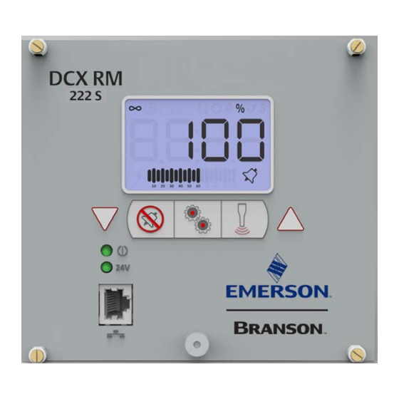
Page 30: Controls And Indicators
Controls and Indicators 2.4.1 DCX RM S Power Supply Front Panel Figure 2.2 DCX RM S Power Supply Front Panel Controls and Indicators Table 2.4 DCX RM S Power Supply Front Panel Controls and Indicators Reference Description For detailed information refer to Figure 2.3 LCD Description Table 2.5 LCD Description. - Page 31 Table 2.4 DCX RM S Power Supply Front Panel Controls and Indicators Reference Description Configuration Key Use the Configuration key to change system registers. Registers are used to change system parameters. For information on using the Configuration key to set system registers see 7.5 Configuring the Power Supply Registers.
-
Page 32: Figure 2.3 Lcd Description
Figure 2.3 LCD Description Table 2.5 LCD Description Reference Description Numeric Display Displays the Power Supply amplitude settings, register numbers, register values or alarm numbers. Continuous Mode Icon Indicates the power supply is running in Continuous mode. When in Continuous mode, the amplitude setting is shown on the numeric display in conjunction with the % icon. - Page 33 Table 2.5 LCD Description Reference Description Number Sign Icon Indicates that the value shown on the numeric display is a register number. Use up and down keys to select a register. For more information see 7.5 Configuring the Power Supply Registers.
-
Page 34: Figure 2.4 Dcx Rm S Power Supply Back Panel
2.4.2 DCX RM S Power Supply Connections Figure 2.4 DCX RM S Power Supply Back Panel Table 2.6 Connections to the DCX RM S Power Supply Item Name Function Line Input Power connector for connecting the line voltage. For wiring Connector details refer to Chapter 5: Installation and... -
Page 35: Welding Systems
Welding Systems 2.5.1 Principle of Operation Thermoplastic parts are welded ultrasonically by applying high frequency vibrations to the parts being assembled. The vibrations, through surface and intermolecular friction, produce a sharp rise in temperature at the welding interface. When the temperature is high enough to melt the plastic, there is a flow of material between the parts. -
Page 36: Glossary
Glossary The following terminology may be encountered when using or operating a DCX RM S Power Supply ultrasonic welding system: Table 2.7 Glossary Name Description The unit which houses the converter/booster/horn stack assembly in a rigid mounting, allowing the stack to move up and down, Actuator either mechanically or pneumatically, applying force to the part at a user-adjustable force and velocity. - Page 37 Table 2.7 Glossary Name Description An offset factor applied to the ultrasonic frequency stored in the Frequency Offset power supply. Gain The ratio of output to input amplitude of a horn or booster. A bar or metal section, usually one half-wavelength-long which Horn transfers vibratory energy to the workpiece.
- Page 38 4000857 REV. 00...
-
Page 39: Chapter 3: Delivery And Handling
Chapter 3: Delivery and Handling Shipping and Handling ........30 Receiving . -
Page 40: Shipping And Handling
Shipping and Handling CAUTION Heavy Object The power supply may be heavy. Handling, unpacking, and installation may require the assistance of a colleague or the use of lifting platforms or hoists. 3.1.1 Environmental Specifications The DCX RM S Power Supply is an electronic unit that converts line voltage to ultrasonic energy and responds to user input for regulating the weld process. -
Page 41: Receiving
Receiving The DCX RM S Power Supply is a sensitive electronic device. Many of its components can be harmed if the unit is dropped or otherwise mishandled. Scope of Delivery Branson equipment is carefully checked and packed before dispatch. It is recommended, however, that you follow the procedure below upon receiving your DCX RM S Power Supply. -
Page 42: Unpacking The Power Supply
Unpacking the Power Supply NOTICE If there are any visible signs of damage to the shipping containers or the product, or you later discover hidden damage, NOTIFY YOUR CARRIER IMMEDIATELY. Save the packing material. The power supply is fully assembled. It is shipped in a sturdy cardboard box. Some additional items are shipped in the box with the power supply. -
Page 43: Take Inventory Of Small Parts
Take Inventory of Small Parts Table 3.4 Small Parts included (=x): Power Supply Assemblies Part or Kit 20 kHz 30 kHz 40 kHz Mylar® plastic film Washer Kit Silicone Grease Spanners (2) * Mylar is a registered trademark of DuPont Teijin Films. 3.4.1 Cables The RF cable connects the power supply to the converter. -
Page 44: Returning Equipment
Returning Equipment If you are returning equipment to Branson Ultrasonic Corporation, please call your Customer Service Representative to receive approval to return the goods. Refer to How to Contact Branson. 4000857 REV. 00... - Page 45 Chapter 4: Technical Specifications Technical Specifications ........36 Physical Description .
-
Page 46: Table 4.2 Electrical Input Operating Voltages
Technical Specifications NOTICE All specifications are subject to change without notice. 4.1.1 Environmental Specifications The DCX RM S Power Supply has the following environmental specifications: Table 4.1 Environmental Specifications Environmental Condition Acceptable Range Ambient Operating Temperature +41° F to +104° F (+5° C to +40° C) Storage / Shipping Temperature -13°... -
Page 47: Chapter 5: Installation And Setup
Table 4.3 Input Current and Fuse Specifications Model Power Current Rating 40 kHz 800 W 5 A Max. @ 200 V / 15 A Fuse Table 4.4 Continuous Duty Max. Power Model Power Continuous Duty. Max. Power 1100 W 330 W 20 kHz 2200 W 660 W... -
Page 48: Physical Description
Physical Description This section describes the physical dimensions of the DCX RM S Power Supply. NOTICE Dimensions are nominal. Table 4.5 Dimensions and Weights of DCX RM S Power Supply Size Width Height Depth Weight 4.2” 8 lb Small 106 mm 3.6 kg 5.6”... -
Page 49: Declaration Of Conformity
Declaration of Conformity Figure 4.1 Declaration of Conformity EU DECLARATION OF CONFORMITY Low Voltage Directive 2014/35/EU, According to 14/30/EU, EMC Directive 20 and RoHS Directive 2011/65/EU. We, the manufacturer BRANSON ULTRASONICS CORPORATION 120 Park Ridge Rd. Brookfield, CT 06804 represented in the community by BRANSON ULTRASONICS, a.s. - Page 50 4000857 REV. 00...
-
Page 51: Chapter 5: Installation And Setup
Chapter 5: Installation and Setup About Installation........42 Installation Requirements . -
Page 52: About Installation
About Installation This chapter is intended to help the installer with the basic installation and setup of your new DCX RM S Power Supply. CAUTION Heavy Object The power supply, and related components are heavy. Handling, unpacking, and installation may require the assistance of a colleague or the use of lifting platforms or hoists. -
Page 53: Installation Requirements
Installation Requirements This section covers the location requirements, mounting options, power supply dimensions, environmental requirements, and electrical requirements, to help you plan and execute your installation successfully. 5.2.1 Installing the DCX RM S Power Supply Drawers in a Customer Rack The power supply units can be installed in any rack complying with the 19”... - Page 54 Figure 5.1 DCX RM S Power Supply Dimensional Drawing (Small) 4000857 REV. 00...
-
Page 55: Figure 5.2 Dcx Rm S Power Supply Dimensional Drawing (Medium)
Figure 5.2 DCX RM S Power Supply Dimensional Drawing (Medium) 4000857 REV. 00... -
Page 56: Figure 5.3 Dcx Rm S Power Supply Dimensional Drawing (Large)
Figure 5.3 DCX RM S Power Supply Dimensional Drawing (Large) 4000857 REV. 00... -
Page 57: Table 5.1 Environmental Requirements
5.2.4 Environmental Requirements Verify the DCX RM S Power Supply is operated in an environment that meets the temperature humidity requirements indicated Table Environmental Requirements. Table 5.1 Environmental Requirements Environmental Condition Acceptable Range Ambient Operating Temperature +41° F to +104° F (+5° C to +40° C) Operating Altitude Up to 6560 ft (2000 m) Humidity... -
Page 58: Installation Steps
Installation Steps WARNING High Voltage Hazard To prevent the possibility of an electrical shock: • Ensure the power source is disconnected before beginning work on line connections • Ensure the power switch on the back of the unit is in the OFF position before making any electrical connections •... -
Page 59: Mount The Power Supply
5.3.1 Mount the Power Supply The cable lengths are limited based on the operating frequency of the welding system. Performance and results can suffer if the RF cable is crushed, pinched, damaged or modified. Contact your Branson Representative if you have special cable requirements. Do not place the power supply on the floor or in other locations that will allow dust, dirt or contaminants to be drawn into the power supply. -
Page 60: Electrical Connections
5.3.3 Electrical Connections Figure 5.5 DCX RM S Power Supply Connections Table 5.3 DCX RM S Power Supply Connections Item Description Input Power Connector. 5.3.13 Input Power Connection. Line Cord RF Connector. 5.3.12 Output Power (RF Cable) Connection. RF Cable (Ferrite End) User I/O Connectors 4000857 REV. -
Page 61: User I/O Connections
5.3.4 User I/O Connections The user I/O is a standard interface for automation, provided on the power supply. It provides the ability to make your own interface for your automation, actuator interface, special control, or reporting needs. The interface cable has a DB15 male connector on one end, and wires on the other end. -
Page 62: Figure 5.6 User I/O Cable Identification And Wire Color Diagram
Figure 5.6 User I/O Cable Identification and Wire Color Diagram User I/O Cable Stripped Jacket one end, DB15 male connector other end (cable length as ordered) Wire Color Diagram Two Colors = Insulator/Stripe Three Colors = Insulator/Stripe/Dot Item Description Part number Insulation Stripe 4000857 REV. -
Page 63: Table 5.4 User I/O Cable Pin Assignments
5.3.5 User I/O Cable Pin Assignments Table 5.4 User I/O Cable Pin Assignments Color Input/Output Signal Type Signal Range Function +Peak Power Limit Digital Output 24 V ±10%, 25 mA White Black Overload Inverted Digital Output 24 V ±10%, 25 mA Brown Brown (Ready) -
Page 64: Table 5.5 Available Digital Input Functions
5.3.6 Available Digital Input Functions Table 5.5 Available Digital Input Functions Function Description External Reset Resets alarm conditions. Activates ultrasonic energy at 10% amplitude for the purpose of External Seek finding the ultrasonic stack resonant frequency. Activates ultrasonic energy at the currently set amplitude. External Start NOTICE DCX RM S Power Supply must be in ready mode before External... -
Page 65: Table 5.7 Available Analog Input Functions
5.3.8 Available Analog Input Functions Table 5.7 Available Analog Input Functions Function Description Valid Range -8 V to +10 V* Controls the amplitude of ultrasonic energy that will Amplitude In be delivered by the power supply. (10% to 100%) Controls the frequency offset to the power supply operating frequency. -
Page 66: Figure 5.7 Typical Digital I/O Wiring Examples
5.3.10 Typical Digital I/O Wiring Examples Figure 5.7 Typical Digital I/O Wiring Examples 5.3.11 Typical Analog I/O Wiring Examples Figure 5.8 Typical Analog I/O Wiring Examples 4000857 REV. 00... -
Page 67: Figure 5.9 Rf Cable Connection
5.3.12 Output Power (RF Cable) Connection Ultrasonic energy is delivered to the SHV connector on the power supply, which is then transmitted to the converter via the RF cable. The RF connector is located on the rear panel of the power supply. To reduce electromagnetic interference (EMI), RF cables are equipped with a ferrite core (plastic case) on one end. -
Page 68: Input Power Connection
5.3.13 Input Power Connection WARNING High Voltage Hazard Ensure all electrical power is off when wiring input power to your DCX RM S Power Supply power connector. To prevent the possibility of an electrical shock, ground the power supply by securing an AWG #14 grounded conductor to the ground screw located next to the air outlet WARNING High Voltage Hazard... -
Page 69: Power Supply Configuration
Power Supply Configuration 5.4.1 Selecting the Alarm Mode The DCX RM S Power Supply activates ultrasonic power after receiving an External Start signal. Ultrasonic power remains on until you turn off the power supply or the External Start signal. The DCX RM S Power Supply response to alarm conditions can be configured to operate in one of two modes: •... - Page 70 For instruction on how to change the power supply settings refer to 7.5 Configuring the Power Supply Registers Chapter 7: Operation and to your DCX RM S Power Supply Web Page Interface Instruction Manual (4000843). NOTICE Consult with Branson before changing any default factory setting. 4000857 REV.
-
Page 71: Assembling The Acoustic Stack
Assembling the Acoustic Stack CAUTION General Warning The following procedure must be performed by a setup person. If necessary, secure the largest portion of a square or rectangular horn in a soft jawed vise. NEVER attempt to assemble or remove a horn by holding the converter housing or the booster clamp ring in a vise. -
Page 72: Figure 5.10 Assembling The Acoustic Stack
Figure 5.10 Assembling the Acoustic Stack Table 5.10 Acoustic Stack Description Item Description Converter Booster Spanner (provided) Horn See stack assembly procedure Vise Jaw protectors (aluminum or soft metal) Vise Table 5.11 Stack Torque Values Frequency Torque 20 kHz 220 in·lb (24.85 N·m) 30 kHz 185 in·lb (21 N·m) 40 kHz... -
Page 73: Table 5.12 Tools
Table 5.12 Tools Tool EDP Number 20 kHz, and 30 kHz Torque Wrench Kit 101-063-787 40 kHz Torque Wrench 101-063-618 20 kHz Spanner Wrench 101-118-039 30 kHz Spanner Wrench 201-118-033 40 kHz Spanner Wrench 201-118-024 Silicone Grease 101-053-002 Mylar Plastic Film Washers (20 kHz) 100-063-357 Mylar Plastic Film Washers (30 kHz) 100-063-632... -
Page 74: Table 5.15 40 Khz System
5.5.3 For a 40 kHz System Table 5.15 40 kHz System Step Action Ensure that the mating surfaces of the converter, booster, and horn are clean, and that the threaded holes are free of foreign material. Coat each interface surface with a thin film of silicon grease - but do not apply silicon grease to a threaded stud or tip. -
Page 75: Figure 5.11 Connecting Tip To Horn
5.5.4 Connecting Tip to Horn 1. Ensure that the mating surfaces of the tip and horn are clean. Remove any foreign matter from the threaded stud and hole 2. Hand assemble the tip to the horn. Assemble dry. Do not use any silicone grease 3. -
Page 76: Converter Cooling
Converter Cooling Converter performance and reliability can be adversely affected if the converter ceramics are subjected to temperatures above 140° F (60° C). The converter front driver temperature should not exceed 122° F (50° C). To prolong converter life and maintain a high degree of system reliability, the converter should be cooled with clean, dry, compressed air, particularly if your application calls for continuous ultrasonic operation. -
Page 77: Table 5.18 Converter Cooling Procedure
If converter cooling is required, use the following steps: Table 5.18 Converter Cooling Procedure Step Action Start with a 50 psi (345 kPa) air source or higher from a 0.06 in (1.5 mm) I.D. orifice Perform a run of welding operations. Immediately after completing the welding run, check the converter temperature. -
Page 78: Testing The Installation
Testing the Installation To test the power supply follow the procedure described in 7.8 Ultrasonics Test Procedure Chapter 7: Operation. 4000857 REV. 00... -
Page 79: Still Need Help
Still Need Help? Branson is pleased that you chose our product and we are here for you! If you need parts or technical assistance with your DCX RM S Power Supply system, call your local Branson representative. Please refer to 1.3 How to Contact Branson for a list of Branson key contacts. - Page 80 4000857 REV. 00...
- Page 81 Chapter 6: Converters and Boosters Converters and Boosters ........72 4000857 REV.
-
Page 82: Converters And Boosters
Converters and Boosters A variety of converters and boosters available for use with the DCX RM S Power Supply are illustrated in the following pages. WARNING High Voltage Hazard To avoid the possibility of electrical shock. Converters need to be properly grounded. -
Page 83: Figure 6.1 20 Khz Typical Converter Dimensions
Figure 6.1 20 kHz typical Converter Dimensions Table 6.1 20 kHz Converter Item Description Air inlet Ground stud SHV connector Grip area 4000857 REV. 00... -
Page 84: Figure 6.2 20 Khz Booster Dimensions
Figure 6.2 20 kHz Booster Dimensions Table 6.2 20 kHz Booster Item Description 1/2 - 20 x 1 - 1/4 stud (Ti boosters) 1/2 - 20 x 1 - 1/2 stud (Al boosters) Grip Ring Diameter Variable Varies with tuning and gain * These dimensions do not vary. -
Page 85: Figure 6.3 20 Khz Converter/Booster/Horn, Typical Dimensions
Figure 6.3 20 kHz Converter/Booster/Horn, Typical Dimensions Table 6.3 20 kHz Converter/Booster/Horn Item Description Converter Booster One-half wavelength horn Recommended clamping area Booster front end diameter will vary with amplitude * Overall horn length can vary beyond these typical dimensions depending on the application. 4000857 REV. -
Page 86: Figure 6.4 30 Khz Converter Dimensions
Figure 6.4 30 kHz Converter Dimensions Table 6.4 30 kHz Converter Item Description Air inlet SHV connector Ground stud Grip area CR-30S and CH-30S are dimensionally identical, and differ only in their respective cooling feature. CR-30S has flow through cooling, and CH-30S has closed loop cooling (air circulates in the converter and returns to its source). -
Page 87: Figure 6.5 30 Khz Booster Dimensions
Figure 6.5 30 kHz Booster Dimensions Table 6.5 30 kHz Booster Item Description 3/8 - 24 x 1 - 1/4 stud Grip Ring Diameter Variable Varies with tuning and gain * These dimensions do not vary. 4000857 REV. 00... -
Page 88: Figure 6.6 30 Khz Converter/Booster/Horn, Typical Dimensions
Figure 6.6 30 kHz Converter/Booster/Horn, Typical Dimensions Table 6.6 30 kHz Converter/Booster/Horn Item Description Converter Booster One-half wavelength horn Recommended clamping area Booster front end diameter will vary with amplitude * Overall horn length can vary beyond these typical dimensions depending on the application. 4000857 REV. -
Page 89: Figure 6.7 40 Khz, 4Tr Converter Dimensions
Figure 6.7 40 kHz, 4TR Converter Dimensions Table 6.7 40 kHz, 4TR Converter Item Description Ground stud SHV connector Grip area 4000857 REV. 00... -
Page 90: Figure 6.8 40 Khz Booster Dimensions
Figure 6.8 40 kHz Booster Dimensions Table 6.8 40 kHz Booster Item Description M8 x 1 - 1/4 stud (Ti boosters) M8 x 1 - 1/2 stud (Al boosters) Grip ring diameter Variable Varies with tuning and gain 4000857 REV. 00... -
Page 91: Figure 6.9 40 Khz Converter/Booster/Horn, Typical Dimensions
Figure 6.9 40 kHz Converter/Booster/Horn, Typical Dimensions Table 6.9 40 kHz Converter/Booster/Horn Item Description Converter Booster One-half wavelength horn Recommended clamping area Booster front end diameter will vary with amplitude * Overall horn length can vary beyond these typical dimensions depending on the application. ** Dimension varies with tuning and gain. -
Page 92: Component Functional Description
6.1.1 Component Functional Description Ultrasonic Stack Converter The converter is mounted in the customer's automation as part of the ultrasonic stack. The ultrasonic electrical energy from the power supply is applied to the converter (sometimes called the transducer). This transforms the high frequency electrical oscillations into mechanical vibrations at the same frequency as the electrical oscillations. - Page 93 Solid Mount Boosters The solid mount booster is a one-half wave-length resonant section made exclusively of titanium. It is mounted between the converter and the horn, modifying the amplitude of vibration applied to the horn and providing a clamping point. The solid mount booster is superior to prior versions in that deflection is minimized.
- Page 94 4000857 REV. 00...
-
Page 95: Chapter 7: Operation
Chapter 7: Operation Setting Primary Parameters ....... . 86 Setting Power Window Limits ......93 Setting the Amplitude. -
Page 96: Setting Primary Parameters
Setting Primary Parameters NOTICE There is a 2 seconds power-up delay before system is in ready mode. After analyzing your specific application, you can determine the Weld Mode to use to weld your parts. A Weld Mode is a set of parameters that governs the weld. (Contact the Branson Ultrasonics Applications Laboratory for more information on determining the best mode for welding your application). -
Page 97: Table 7.2 Selecting Continuous Mode
7.1.1 Selecting Continuous Mode In this mode, ultrasonic energy will be delivered continuously while the start signal is present. Within Continuous Mode, you can also select several other parameters, ranging from afterburst to limits and cutoffs. For more information on setting the optional parameters within Continuous Mode, or any other welding mode, refer to the DCX Web Page Instruction Manual. - Page 98 Table 7.2 Selecting Continuous Mode Step Action Reference Use the Up/Down arrow keys to select value 0 (Continuous mode), then press the Configuration key to confirm the selection. Continuous mode icon and amplitude value will be displayed. 4000857 REV. 00...
-
Page 99: Table 7.3 Time Mode Parameters
7.1.2 Selecting Time Mode You can use Time Mode to select the length of time that ultrasonic energy is applied to your parts. Within Time Mode, you can also select several other parameters, ranging from afterburst to limits and cutoffs. For more information on setting the optional parameters within Time Mode, or any other welding mode, refer to the DCX Web Page Instruction Manual. -
Page 100: Table 7.5 Setting Energy Mode Parameters
Table 7.4 Selecting Time Mode Step Action Reference Once you have reached register 138, press the Configuration key. The register value will be displayed; this is indicated by the circle icon. Use the Up/Down arrow keys to select value 1 (Time mode), then press the Configuration key to confirm the selection. -
Page 101: Table 7.6 Energy Mode Parameters
7.1.3 Selecting Energy Mode You can use Energy Mode to select the amount of ultrasonic energy that is applied to your parts. Within Energy Mode, you can also select several other parameters, ranging from afterburst to limits and cutoffs. For more information on setting the optional parameters within Energy Mode, or any other welding mode, refer to the DCX Web Page Instruction Manual. -
Page 102: Table 7.8 Setting Energy Mode Parameters
Table 7.7 Selecting Energy Mode Step Action Reference Once you have reached register 138, press the Configuration key. The register value will be displayed; this is indicated by the circle icon. Use the Up/Down arrow keys to select value 2 (Energy mode), then press the Configuration key to confirm the selection. -
Page 103: Setting Power Window Limits
Setting Power Window Limits If power window high or power window low limits are enabled, it will display a single slowly blinking segment for the high limit and a single slowly blinking segment for the low limit in the bargraph. In case of a window limit alarm, the respective segment will blink faster. -
Page 104: Table 7.9 Power Window Limit Low Parameters
7.2.1 Power Window Limit Low Table 7.9 Power Window Limit Low Parameters Parameter Default Max. Value Min. Value Power Window Limit 100%* 0% (Off) NOTICE *Max. value should be 5% below the window limit high value. If window limit high is set to off, max. value is 100%. Table 7.10 Power Window Limit Low Operational Sequence Step Action... - Page 105 Table 7.10 Power Window Limit Low Operational Sequence Step Action Reference Once you have reached register 155, press the Configuration key. The register value will be displayed; this is indicated by the circle icon. Use the Up/Down arrow keys to select the desired power window limit low value, then press the Configuration key to confirm the selection.
-
Page 106: Table 7.11 Power Window Limit High Parameters
7.2.2 Power Window Limit High Table 7.11 Power Window Limit High Parameters Parameter Default Max. Value Min. Value Power Window Limit 100% 0% (Off)* High NOTICE *Minimum value should be 5% above the window limit low value. If window limit high is set to off, min. value is 0%. Table 7.12 Power Window Limit High Operational Sequence Step Action... - Page 107 Table 7.12 Power Window Limit High Operational Sequence Step Action Reference Once you have reached register 156, press the Configuration key. The register value will be displayed; this is indicated by the circle icon. Use the Up/Down arrow keys to select the desired power window limit high value, then press the Configuration key to confirm the selection.
-
Page 108: Setting The Amplitude
Setting the Amplitude 7.3.1 Using the Front Panel Controls At power up the DCX RM S Power Supply will display the last amplitude setting on the LCD. It can also be set to show weld mode. Figure 7.2 LCD at Power Up Table 7.13 Setting the Amplitude Using the Front Panel Controls Step Action... -
Page 109: Figure 7.3 Lcd When In External Amplitude Control Mode
7.3.2 Using External Amplitude Control When External Amplitude Control is enabled, the front panel amplitude control is disabled and the LCD displays four dashes (see Figure 7.3 LCD when in External Amplitude Control Mode below). Figure 7.3 LCD when in External Amplitude Control Mode The ultrasonic amplitude can be controlled using one of the two analog input pins on the user I/O connector (pins 17 and 18). -
Page 110: Resetting The Power Supply Alarms
Resetting the Power Supply Alarms You need to reset the weld system when you get an overload. When there is an overload, the alarm icon appears on the front panel LCD and the General Alarm output on the user I/O connector becomes active. The procedure for resetting the power supply depends on the power supply alarm settings. -
Page 111: Configuring The Power Supply Registers
Configuring the Power Supply Registers At power up the DCX RM S Power Supply will display the last amplitude setting, this is indicated by the percentage icon (%) on the LCD. Refer to Figure 7.2 LCD at Power Table 7.15 Steps to Configure the Power Supply Registers Step Action Reference... - Page 112 Table 7.15 Steps to Configure the Power Supply Registers Step Action Reference Press and release the Up or Down arrow keys to enter the desired value at 1 increments. Press and hold down the Up and Down arrow keys and the value will auto increment at 1 increments every quarter of a second.
-
Page 113: Table 7.16 Power Supply Registers
7.5.1 Power Supply Registers Table 7.16 Power Supply Registers Default Max. Min. Register Description Value Value Value System software version Bar graph identification after weld complete 0: Power 1: Frequency External amplitude control - user analog input 0: Off 1: On Amplitude ramp time (ms) 1000 Store frequency at end of weld... - Page 114 Table 7.16 Power Supply Registers Default Max. Min. Register Description Value Value Value IP address - 4 Gateway for IP address 1 Gateway for IP address 2 Gateway for IP address 3 Gateway for IP address 4 Subnet mask for IP address 1 Subnet mask for IP address 2 Subnet mask for IP address 3 Subnet mask for IP address 4...
- Page 115 Table 7.16 Power Supply Registers Default Max. Min. Register Description Value Value Value Power window limit high 0: Off 1 to 100: Power limit high (must be higher than register 155) Memory clear when external reset through 0: No memory clear 1: Memory clear 4000857 REV.
-
Page 116: Lcd Bar-Graph
LCD Bar-Graph While ultrasonic power is active the LCD will always display the power value on the 20- segment LCD bar-graph as a percentage of the maximum output power. At the end of a weld or test cycle, the bar-graph is factory set to represent the cycle’s peak power as a percentage of the maximum output power. -
Page 117: Table 7.18 Frequency Bar-Graph Interpretation - 20 Khz (50 Hz Segment)
7.6.2 Frequency Bar-Graph Interpretation The actual frequency depends on the power supply’s operating frequency. Use tables below to interpret frequency bar-graph readings. NOTICE If there is a test overload or an external memory reset signal is received, then the 50% segment will be displayed and blinking. Table 7.18 Frequency Bar-Graph Interpretation - 20 kHz (50 Hz Segment) 20 kHz (50 Hz/Segment) Table 7.19 Frequency Bar-Graph Interpretation - 30 kHz (76 Hz Segment) -
Page 118: Table 7.20 Frequency Bar-Graph Interpretation - 40 Khz (100 Hz/Segment)
Table 7.20 Frequency Bar-Graph Interpretation - 40 kHz (100 Hz/Segment) 40 kHz (50 Hz/Segment) Table 7.21 Frequency Bar-Graph Interpretation Examples Description Reference In this example the bar is located in the 11 segment. If the power supply is a 20 kHz unit, the stack is running in the frequency range of 19,975 Hz to 20,024 Hz. -
Page 119: Web
Web Page Interface The DCX RM S Power Supply Power Supply Web Page Interface provides access, via Ethernet connection, to power supply information, diagnostics, and configuration web pages. Communication can be established point-to-point or through a local area network. 7.7.1 System Requirements To connect to the DCX RM S Power Supply Web Page Interface you will need a PC running a Windows®... - Page 120 7. Right click on Local Area Connection and select Properties to bring up the Networking tab 8. Highlight Internet Protocol Version 4 (TCP/IPv4) from the list and click on Properties 4000857 REV. 00...
- Page 121 9. Use the following IP address: IP address: 192.168.10.101 Subnet mask: 255.255.255.0 10.Click OK. Close the rest of the dialog boxes 11.Open the Internet Explorer web browser (version 7 and up) 12.In the address bar type the following address: http://192.168.10.100. Press Enter 13.This will bring up the DCX RM S Power Supply Web Page interface 14.Enter a user ID number (any number up to 9 digits long) 4000857 REV.
- Page 122 7.7.2.2 Point to Point Connection (Windows XP) 1. To connect directly to the DCX RM S Power Supply Web Page Interface using a PC with ® Windows XP operating system, complete the following steps: 2. Connect the power supply to a computer via the Ethernet port 3.
- Page 123 9. Use the following IP address: IP address: 192.168.10.101 Subnet mask: 255.255.255.0 10.Click OK. Close the rest of the dialog boxes 11.Open the Internet Explorer web browser (version 7 and up) 12.In the dress bar type the following address: http://192.168.10.100. Press Enter 13.This will bring up the DCX RM S Power Supply Web Page interface 14.Enter a user ID number (any number up to 9 digits long) 7.7.3...
-
Page 124: Ultrasonics Test Procedure
Ultrasonics Test Procedure The Ultrasonics Test function measures ultrasonic power dissipated by the ultrasonic stack with no load. The ultrasonics test procedure involves an automatic matching of the frequency of the power supply to the frequency of the converter-booster-horn stack. WARNING High Voltage Hazard Ensure that no one is in contact with the horn when testing the power... -
Page 125: Table 7.22 Power Supply Ultrasonic Test Procedure (Front Panel)
7.8.1 Using the Front Panel Controls NOTICE To use the front panel controls, the DCX RM S Power Supply unit must be in manual mode. Table 7.22 Power Supply Ultrasonic Test Procedure (Front Panel) Step Action Reference Press the test key for 1-2 seconds, then release. -
Page 126: Figure 7.4 Test Connections
7.8.2 Using the I/O Connections Table 7.23 Power Supply Ultrasonic Test Procedure (User I/O) Step Action Reference Wire the necessary I/O signals as shown Refer to Figure 7.4 Test Figure 7.4 Test Connections, or using a Connections below. similar setup. Send an External Test signal for 1-2 seconds. -
Page 127: Chapter 8: Maintenance
Chapter 8: Maintenance General Maintenance Considerations ......118 Preventive Maintenance ........120 Calibration . -
Page 128: General Maintenance Considerations
General Maintenance Considerations WARNING High Voltage Hazard Power supplies produce high voltage. To avoid the possibility of an electrical shock, you should always power down your system prior to repairing any portion of it. CAUTION General Warning When performing maintenance on the welder, make sure that no other automated systems are active. - Page 129 NOTICE To prevent circuit damage from electrostatic discharge, always service the power supply on a static-dissipative surface, while wearing a properly grounded wrist strap. 4000857 REV. 00...
-
Page 130: Preventive Maintenance
Preventive Maintenance The following preventive measures help assure long term operation of your Branson DCX RM S Power Supply equipment. 8.2.1 Periodically Clean the Equipment NOTICE Use only anti-static vacuum cleaners to prevent damage from electrostatic discharge to your power supply. Air is continuously drawn into the power supply. -
Page 131: Table 8.1 Stack Reconditioning Procedure
8.2.2 Recondition the Stack (Converter, Booster, and Horn) NOTICE Never clean the converter-booster-horn stack mating surfaces by using a buffing wheel or by filing. Welding system components work most efficiently when the converter-booster-horn stack mating surfaces are flat, in solid contact, and free from fretting corrosion. Poor contact between mating surfaces wastes power output, makes tuning difficult, increases noise and heat, and may cause damage to the converter. -
Page 132: Figure 8.1 Reconditioning Stack Mating Surfaces
Table 8.1 Stack Reconditioning Procedure Step Action Rotate the part another 120 degrees to the next spanner-wrench hole, and repeat the lapping procedure in step 6. Re-examine the mating surface. If necessary, repeat steps 2-5 until you remove most of the contaminant. Remember, this should not require more than two to three complete rotations for an aluminum horn or booster;... -
Page 133: Table 8.3 Stack Torque Values
8.2.2.1 Stack Reassembly Process Table 8.3 Stack Torque Values Frequency Torque 20 kHz 220 in·lb (24.85 N·m) 30 kHz 185 in·lb (21 N·m) 40 kHz 95 in·lb (10.73 N·m) For a 20 kHz System Table 8.4 Stack Reassembly for a 20 kHz System Step Action Clean the mating surfaces of the converter, booster, and horn. -
Page 134: Table 8.5 Stack Reassembly For A 30 Khz System
For a 30 kHz System Table 8.5 Stack Reassembly for a 30 kHz System Step Action Clean the mating surfaces of the converter, booster, and horn. Remove any foreign material from the threaded holes. Install the threaded stud into the top of the booster. Torque to 290 in·lb (32.76 N·m). -
Page 135: Table 8.7 Stud Torque Values
8.2.3 Stud Torque Values Table 8.7 Stud Torque Values Used on Stud Size Torque EDP # 1/2 in x 20 x 1-1/4 in 100-098-370 20 kHz 450 in·lb, 50.84 N·m 1/2 in x 20 x 1-1/2 in 100-098-123 30 kHz 3/8 in x 24 x 1 in 290 in·lb, 32.76 N·m 100-298-170R... -
Page 136: Calibration
Calibration This product does not normally require scheduled calibration. However, if you are operating under any type of regulatory requirements, you may need to calibrate the equipment according to that schedule and set of standards. Contact Branson for details. 4000857 REV. 00... -
Page 137: Recommended Spare Stock
Recommended Spare Stock This section provides lists of replacement parts, system cables, and suggested spares. 8.4.1 System Cables You can order the following cables: Table 8.8 DCX RM S Power Supply System Cables Description 100-240-383 Cable, RF 8 ft (2.5 m) 100-240-384 Cable, RF 15 ft (4.5 m) 100-240-385... -
Page 138: Table 8.9 Suggested Spares
8.4.2 Suggested Spares Table 8.9 Suggested Spares 6-12 Description EDP# 1-4 Units 14+ Units Units Refer to Table 8.10 Converters Converter Compatible with the DCX RM S Power Supply Refer to Table 8.11 DCX RM S Booster Power Supply Compatible Boosters Horn As Ordered... -
Page 139: Table 8.10 Converters Compatible With The Dcx Rm S Power Supply
8.4.3 Converters Compatible with the DCX RM S Power Supply Table 8.10 Converters Compatible with the DCX RM S Power Supply Where used Model Connector Part Number CR-20* 3-pin MS connector 101-135-060R CR-20S SHV connector 125-135-115R SHV connector with 3 ft (0.9 m) CR-20C 159-135-210R cable... -
Page 140: Table 8.11 Dcx Rm S Power Supply Compatible Boosters
8.4.4 DCX RM S Power Supply Compatible Boosters Table 8.11 DCX RM S Power Supply Compatible Boosters Type of Booster Description Part Number Titanium, 1:0.6 (Purple) 101-149-095 Titanium, 1:1 (Green) 101-149-096 Solid Mount (1/2-20 horn stud) Titanium, 1:1.5 (Gold) 101-149-097 20 kHz Titanium, 1:2 (Silver) 101-149-098... - Page 141 Table 8.11 DCX RM S Power Supply Compatible Boosters Type of Booster Description Part Number Aluminum, 1:0.6 (Purple) 101-149-087 Aluminum, 1:1 (Green) 101-149-079 Aluminum, 1:1.5 (Gold) 101-149-080 Aluminum, 1:2 (Silver) 101-149-081R Standard Series (M8 x 1.25 horn stud) Aluminum, 1:2.5 (Black) 101-149-082 40 kHz Titanium, 1:1 (Green)
-
Page 142: Table 8.12 Other Items Used With The Dcx Rm S Power Supply
8.4.5 Other Items used with the DCX RM S Power Supply Table 8.12 Other Items used with the DCX RM S Power Supply Product Description Part No. Silicone grease For use with 40 kHz systems 101-053-002 Kit, 10 each (1/2 in and 3/8 in) 100-063-357 Mylar Plastic Film Washers... -
Page 143: Troubleshooting
Troubleshooting If you have a problem operating the DCX RM S Power Supply, take the following steps: Table 8.13 Troubleshooting Step Action Make sure the converter-booster-horn stack is properly assembled and installed. For instructions on reconditioning stack component surfaces, refer to 8.2.2 Recondition the Stack (Converter, Booster, and Horn). -
Page 144: Table 8.14 Troubleshooting Common Electrical Problems
8.5.1 Common Electrical Problems NOTICE If the circuit breaker fails more than once, this usually indicates that another component has failed. Continue troubleshooting other components. Table 8.14 Troubleshooting Common Electrical Problems Problem Check Solution Main circuit breaker trips when plugging the power Inspect line connection cables. -
Page 145: Table 8.15 Troubleshooting Ultrasonic Power Problems
8.5.2 Ultrasonic Power Problems Table 8.15 Troubleshooting Ultrasonic Power Problems Problem Check Solution Check connector cables, Replace defective replace if failed. cables. Ultrasonic power delivered Chapter 7: to horn; no indication on Operation 7.8 bar graph. Test power supply. Ultrasonics Test Procedure Failed or missing stack. -
Page 146: Table 8.16 Troubleshooting Weld Cycle Problems
8.5.3 Weld Cycle Problems Table 8.16 Troubleshooting Weld Cycle Problems Problem Check Solution Unsuitable horn or booster selection. Plastic part material varies. Mold release lubricant in weld Contact Branson Applications Full ultrasonic power area. not delivered. Unsuitable joint design. Unsuitable or misaligned part fixture. -
Page 147: Appendix A: Signal Diagrams
Appendix A: Signal Diagrams Signal Diagrams ........138 4000857 REV. -
Page 148: Signal Diagrams
Signal Diagrams Figure A.1 Continuous *Register #157 must be set to 1. 4000857 REV. 00... -
Page 149: Figure A.2 Continuous, Overload Error
Figure A.2 Continuous, Overload Error *Register #157 must be set to 1. 4000857 REV. 00... -
Page 150: Figure A.3 Time
Figure A.3 Time *Register #157 must be set to 1. 4000857 REV. 00... -
Page 151: Figure A.4 Time, Window Error
Figure A.4 Time, Window Error *Register #157 must be set to 1. 4000857 REV. 00... -
Page 152: Figure A.5 Time, Overload Error
Figure A.5 Time, Overload Error *Register #157 must be set to 1. 4000857 REV. 00... -
Page 153: Figure A.6 Energy
Figure A.6 Energy *Register #157 must be set to 1. 4000857 REV. 00... -
Page 154: Figure A.7 Energy, Window Error
Figure A.7 Energy, Window Error *Register #157 must be set to 1. 4000857 REV. 00... -
Page 155: Figure A.8 Energy, Overload Error
Figure A.8 Energy, Overload Error *Register #157 must be set to 1. 4000857 REV. 00... - Page 156 4000857 REV. 00...
- Page 157 Index about Installation 42 Actuator 26 Alarm 26 alarm configuring 59 latching 59 modes 59 Amplitude 26 amplitude controlling 59 start ramp 59 Amplitude Control 26 amplitude control 59 applications 25 autotune with memory (AT/M) 15 Autotuning 17 bar graph 106 frequency interpretation 107 power interpretation 106 bend radius 48...
- Page 158 converter 19, 82 cooling 66 dimensions 38, 72 part numbers 129 Counters 26 Degating 26 Digital Amplitude Setting 17 drop test 30 electrical input operating voltages 36 Energy Director 26 environmental requirements 47 specifications 30 External Amplitude Control 26 External Frequency Control 26 Fixture 26 Flash 26 Forming 26...
- Page 159 steps 48 testing 68 Interface 27 inventory of small parts 33 Joint 27 LCD 17 bar graph 106 frequency interpretation power interpretation description 22 viewing angle 49 line input connector 24 Line Regulation 17 line regulation 15 Load Regulation 17 load regulation 15 maintenance 117 general considerations 118...
- Page 160 models 14, 15 mounting 49 Ramp Starting 17 receiving the equipment 31 returning equipment 34 safety general precautions 5 maintenance 118 symbols, meaning 2 Seek 18, 27 seek ramp time 59 time 59 timed 15, 59 shipping and handling 30 shock 30 solid mount boosters 83 special cable requirements 49...
- Page 161 User ID 17, 27 vibration 30 Web Page Interface 18 web page interface 15, 114 point-to-point connection Windows Vista and Windows 7 Windows XP Weld Parameters 86 Weld System 27 weld system applications 25 welding systems 25 Window Limit High 96 Window Limit Low 94 Window Limits 93 4000857 REV.
- Page 162 4000857 REV. 00...
Need help?
Do you have a question about the Branson DCX RM S and is the answer not in the manual?
Questions and answers