Advertisement
NetSure 501 A50, NetSure 501 AA0, NetSure 701 A51
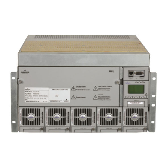
19-Inch Subrack Power Supply System
User Manual
Version
Revision date
BOM
Emerson Network Power provides customers with technical support. Users may contact the nearest
Emerson local sales office or service center.
Copyright © 2008 by Emerson Network Power Co., Ltd.
All rights reserved. The contents in this document are subject to change without notice.
Emerson Network Power Co., Ltd.
Address: No.1 Kefa Rd., Science & Industry Park, Nanshan District 518057, Shenzhen China
Homepage: www.emersonnetworkpower.com.cn
E-mail: support@emersonnetwork.com.cn
V1.0
June 13, 2008
31011680
Advertisement

Related Manuals for Emerson NetSure 501 A50


Summary of Contents for Emerson NetSure 501 A50
- Page 1 Revision date June 13, 2008 31011680 Emerson Network Power provides customers with technical support. Users may contact the nearest Emerson local sales office or service center. Copyright © 2008 by Emerson Network Power Co., Ltd. All rights reserved. The contents in this document are subject to change without notice.
- Page 2 When operating Emerson products, the safety rules in the industry, the general safety points and special safety instructions specified in this book must be strictly observed.
- Page 3 Notice Notice The static electricity generated by the human body will damage the static sensitive elements on PCBs, such as large-scale ICs. Before touching any plug-in board, PCB or IC chip, ESD wrist strap must be worn to prevent body static from damaging the sensitive components.
- Page 4 The method of disabling BLVD is: Set “BLVD Enable” item of the monitoring module to “N”. Refer to 4.7.3LVD Parameter Description, 5.5.2Battery Management Parameters or 6.7.3Battery Settings for setting method. Notice Notice The advantage of enabling BLVD is protecting the batteries from over-discharge when the battery voltage is low. The disadvantage of enabling BLVD is that when the battery voltage drops down to a certain value, all the loads (including non- priority loads and priority loads) will be cut off due to battery disconnection.
-
Page 5: Table Of Contents
Contents Chapter 1 Overview................................1 Chapter 2 Installation Instruction............................4 Chapter 3 Installation Testing............................10 Chapter 4 Use Of Monitoring Module M500D........................13 Chapter 5 Use Of Monitoring Module M800D........................36 Chapter 6 Use Of Monitoring Module M501D .........................82 Chapter 7 Alarm Handling.............................. 105 Appendix 1 Technical And Engineering Data.........................108 Appendix 1... -
Page 6: Chapter 1 Overview
This chapter introduces model description, composition and configuration, and features. The “system” in this manual refers to the PS48150-3B/1800 (NetSure 501 A50) (abbreviated as “NetSure 501 A50”), PS48300-3C/1800 (NetSure 501 AA0) (abbreviated as “NetSure 501 AA0”) and PS48300-3A/3200 (NetSure 701 A51) &... - Page 7 Dummy plate Rectifier Figure 1.4 NetSure 701 A51 (PS48300-3A/3200-X2) system structure System configuration The configurations of the power supply system are described in Table 1-1. NetSure 501 A50, NetSure 501 AA0, NetSure 701 A51 19-Inch Subrack Power Supply System User Manual...
- Page 8 The rectifier uses the active Power Factor Compensation (PFC) technology, raising the power factor to 0.99 Wide AC input voltage range: 85V ~ 290V (NetSure 701 A51) or 85Vac ~ 300Vac (NetSure 501 A50 & NetSure 501 AA0) The rectifier uses soft switching technology, raising the system efficiency to 89% (R48-1800)/ 90% (R48-3200) ...
-
Page 9: Chapter 2 Installation Instruction
The CSA of DC cable depends on the current flowing through the cable and the allowable voltage drop. To select the battery cable CSA, see Table 2-1. Select the DC load cable CSA according to the Table 2-2: NetSure 501 A50, NetSure 501 AA0, NetSure 701 A51 19-Inch Subrack Power Supply System User Manual... - Page 10 Figure 2-4 with a Phillips screwdriver. Figure 1.1 Installation size of NetSure 501 A50 (unit: mm) 466.8 Figure 1.2 Installation size of NetSure 501 AA0 (unit: mm) NetSure 501 A50, NetSure 501 AA0, NetSure 701 A51 19-Inch Subrack Power Supply System User Manual...
- Page 11 Feed all the cables into the subrack from top of the subrack. Take the NetSure 701 A51 power supply system as an example, the position of the connection terminals are shown in Figure 2-5. Connect the AC input cables to the AC input MCB. NetSure 501 A50, NetSure 501 AA0, NetSure 701 A51 19-Inch Subrack Power Supply System User Manual...
- Page 12 S6415X2 user connector board cable connection Take the NetSure 501 A50 power supply system as an example, the position of the user connector board is shown in Figure 2-6. Two communication interfaces are located in the panel: Ethernet and RS232 interface. The power supply system can be connected to Ethernet through the Ethernet interface or connected to modem through RS232 interface.
- Page 13 Relay output 5 normal close DO5_NC Relay output 6 normal close DO6_NC Relay output 5 common DO5_COM Relay output 6 common DO6_COM Relay output 5 normal open DO5_NO NetSure 501 A50, NetSure 501 AA0, NetSure 701 A51 19-Inch Subrack Power Supply System User Manual...
- Page 14 In the modem mode, the monitoring module will initialize modem upon power-on, reset or upon communication interruptions that last more than one hour. NetSure 501 A50, NetSure 501 AA0, NetSure 701 A51 19-Inch Subrack Power Supply System User Manual...
-
Page 15: Chapter 3 Installation Testing
For monitoring module parameter setting method, see 4.7Setting System Parameters if using M500D. 5.2.5Parameter Set if using M800D. See 5.7 Setting System Parameters if using M501D. NetSure 501 A50, NetSure 501 AA0, NetSure 701 A51 19-Inch Subrack Power Supply System User Manual... - Page 16 1%. Check the number of the rectifier through the monitoring module. The number should be consistent with the actual number. NetSure 501 A50, NetSure 501 AA0, NetSure 701 A51 19-Inch Subrack Power Supply System User Manual...
- Page 17 If repairing is needed, please fill in the FAILURE REPORT and send the report together with the defective unit to the repairing center for fault analysis. NetSure 501 A50, NetSure 501 AA0, NetSure 701 A51 19-Inch Subrack Power Supply System User Manual...
-
Page 18: Chapter 4 Use Of Monitoring Module M500D
As for those important parameters related to battery management, such as BLVD, you should be fully aware of their influence upon the system before you change their values. NetSure 501 A50, NetSure 501 AA0, NetSure 701 A51 19-Inch Subrack Power Supply System User Manual... -
Page 19: Chapter 5 Use Of Monitoring Module M800D
The maintenance operation can be conducted only when the battery management mode is set to “Manual”. The maintenance includes battery FC, BC and test, load power off/on, battery power off/on and rectifier voltage trimming, current limit, switch control and resetting. NetSure 501 A50, NetSure 501 AA0, NetSure 701 A51 19-Inch Subrack Power Supply System User Manual... - Page 20 The default is the percentage. During the normal BC/FC management, the monitoring module regards the rated capacity as the capacity that each NetSure 501 A50, NetSure 501 AA0, NetSure 701 A51 19-Inch Subrack Power Supply System User Manual...
Need help?
Do you have a question about the NetSure 501 A50 and is the answer not in the manual?
Questions and answers