Epson Stylus PRO 7500 Service Manual
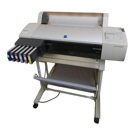
Color large format inkjet printer
Hide thumbs
Also See for Stylus PRO 7500:
- Reference manual (184 pages) ,
- Startup manual (76 pages) ,
- Assembly and setup instructions (36 pages)

Related Manuals for Epson Stylus PRO 7500


Summary of Contents for Epson Stylus PRO 7500
-
Page 1: Service Manual
SERVICE MANUAL Color Large Format Inkjet Printer EPSON Stylus PRO 7500 ® SEIJ00005... - Page 2 The contents of this manual are subject to change without notice. n All efforts have been made to ensure the accuracy of the contents of this manual. However, should any errors be detected, SEIKO EPSON would greatly appreciate being informed of them.
- Page 3 2. MAKE CERTAIN THAT THE SOURCE VOLTAGES IS THE SAME AS THE RATED VOLTAGE, LISTED ON THE SERIAL NUMBER/RATING PLATE. IF THE EPSON PRODUCT HAS A PRIMARY AC RATING DIFFERENT FROM AVAILABLE POWER SOURCE, DO NOT CONNECT IT TO THE POWER SOURCE.
-
Page 4: Disassembly And Assembly
This manual describes basic functions, theory of electrical and mechanical CHAPTER 6. MAINTENANCE operations, maintenance and repair procedures of EPSON EPSON Stylus PRO Provides preventive maintenance procedures and the 7500. The instructions and procedures included herein are intended for the... -
Page 5: Maintenance
Symbols Used in This Manual Various symbols are used throughout this manual either to provide additional information on a specific topic or to warn of possible danger present during a procedure or an action. Be aware of all symbols when they are used, and always read WARNING, CAUTION or NOTE messages. - Page 6 Revision Status Revision Issued Date Description Rev. A August 31, 2000 First Release...
-
Page 7: Table Of Contents
Product Description Maintenace Mode..................48 HEX Dump ....................49 Features ....................... 11 Panel Display Language Selection ..............49 Consumable Products & Options ............12 M/W Mode Setting ..................49 Maintenance Mode 2................50 Print Specifications ..................13 Printing Specifications ...................13 Ink Cartridge Size Select................53 Character Specifications ................13 Inter-User Transport Mode ................ - Page 8 Fatal Errors .....................85 Smudged or Marred Printout (Reverse side) ..........94 White or Black Banding ................94 Errors That Require a Service Technician............ 87 Maintenance Call 0100 ..................87 Disassembly & Assembly Service Call 00000100 ...................87 Service Call 00000101 ...................87 Summary ...................... 96 Service Call 00010000 ...................87 Warnings ....................
- Page 9 Range of Backed Up Parameters ..............176 Bi-D #4 Adjustment Check Pattern ............233 Firmware Update................... 177 Required Materials ..................233 Updating Firmware Via the PC ..............177 Operating Environment and Preliminary Preparations ........233 Updating Firmware From a Memory Card ..........178 Bi-D #4 Adjustment Check Pattern .............233 Self-diagnostic Function ................
-
Page 10: Product Description
C H A P T E R PRODUCT DESCRIPTION... -
Page 11: Features
Revision A 1.1 Features The EPSON Stylus Pro 7500 is an 24-inch wide, 6-color ink jet printer with professional color output. It has the same printheads as the EPSON Stylus Pro 9000. The EPSON Stylus Pro 7500 provides the following major features and more. -
Page 12: Consumable Products & Options
EPSON Stylus Pro 7500 Revision A ¬ Signifies a number that varies by market. 1.1.1 Consumable Products & Options The consumables and options that can be used with the Stylus Pro 7500 are shown below. Table 1-2. Consumables & Options Name Code... -
Page 13: Print Specifications
Printing System: Ink jet Type Faces: Head nozzle arrangement: black = 64 nozzles (32 nozzles x 2 rows) Bitmap LQ fout : EPSON Courier 10 CPI Color = 320 nozzles (Cyan, magenta, yellow, light cyan and light magenta, 64 Control Code: ESC/P Raster... -
Page 14: Paper Specification
EPSON Stylus Pro 7500 Revision A The remaining paper length when the paper is cut off from PAPER SPECIFICATION the roll. (Reference): approx. 30 cm. Roll Paper: [Compatible papers] [EPSON Special Paper] The following papers can be loaded in this machine, but it... - Page 15 EPSON Stylus Pro 7500 Revision A Cut Sheet Paper: [Papers that can be loaded] [Plain Paper] Loading of the following papers into this printer is For the following specifications, only the lack of possible, but for papers other than the following plain hindrance for paper feed through is guaranteed.
- Page 16 EPSON Stylus Pro 7500 Revision A Printable Area: See the table and figure below. [EPSON Special Papers] Shown below. Table 1-8. Printable Area Table 1-7. Specifications of EPSON Special Papers Heading Roll Paper Cut Sheets Photo 210 ~ 610mm 210 ~ 610mm...
- Page 17 EPSON Stylus Pro 7500 Revision A Paper Feed Printable Area Figure 1-1. Printable Area Paper Set Lever: • By opening the paper Set lever, paper support is canceled and the paper can be set. • By closing the paper Set lever, the set paper is held in place and printing is enabled.
-
Page 18: Ink (Dye Ink Cartridge)
If 40°C, within 1 month printer Usable ink cartridges: For Stylus Pro 7500 100 ml Ink Cartridge For Stylus Pro 9500 200 ml Ink Cartridge *1 NOTE: If the above ink cartridge *1) uses, it is necessary to set it according to 1.9 “Ink Cartridge Size Select.”... -
Page 19: Conformity/Safety Approvals
European Model EN60950 (VDE) [Cutter] 2,000 Sheets (A1) EMC: Periodic Replacement Parts Maintenance Kit, Stylus Pro 7500 (No. 1054038) US Model FCC part 15 subpart B class B This kit consists of the following parts. CSA C108.8 class B Waste ink absorbent, pump assembly, cap assembly, flushing box assembly, head European Model EN 55022 (CISPR Pub. -
Page 20: Environmental Conditions
EPSON Stylus Pro 7500 Revision A ENVIRONMENTAL CONDITIONS Temperature&Humidity See the following table. Humidity (%) Table 1-11. Environmental Conditions Condition Temperature Humidity Notes • Less than a month at 40°C 10~35°C Operating 20~80% (104°F) (50~95°F) • Less than 120 hours at 60°C -20~40°C... -
Page 21: Controller Specifications
EPSON Stylus Pro 7500 Revision A Cutting conditions and cutting system: See the table below. CONTROLLER SPECIFICATIONS Table 1-13. Cutting Conditions and Cutting System Hitachi SH7043 33 Mhz Cutting Conditions Cutting System When paper width sensor = ON. Initial cut (Manual cutting when the paper is... -
Page 22: External Dimensions / Installation Environment / Weight
EPSON Stylus Pro 7500 Revision A Installation Environment. EXTERNAL DIMENSIONS / INSTALLATION ENVIRONMENT / See the figure below. WEIGHT External Dimensions 1100 x 572 x 560 (Width x Depth x Height) See the figure below. Other Obstacles Paper Eject Direction... -
Page 23: Interfaces
EPSON Stylus Pro 7500 Revision A 1.3 Interfaces This printer is equipped with a parallel and a USB interface as standard equipment. As an option, it can also be equipped with a Type B Interface. 1.3.1 Parallel Interface COMPATIBILITY MODE... - Page 24 EPSON Stylus Pro 7500 Revision A Table 1-14. Parallel Interface (Compatibility Mode) Table 1-14. Parallel Interface (Compatibility Mode) Signal Return Signal Return Pin No. Source Function Pin No. Source Function Name Pin No. Name Pin No. Strobe pulse (When Low, data can be read.
- Page 25 EPSON Stylus Pro 7500 Revision A *1 The return side means the twisted pair return and is connected to the signal ground level. Data Transmission Timing Furthermore, when interfacing, a twisted pair cable should definitely be used for each signal and the return side should definitely connected.
-
Page 26: Nibble Mode
[00H] [47H] MFG: EPSON CMD: ESCPL2, BDC; MDL:Stylus [SP] Pro [SP] 7500 CLS: PRINTER DES: EPSON [SP] Stylus [SP] Pro [SP] 7500; *: [SP] is code 20<H>. See the table below for the signal layout and signal names. Product Description Interfaces... -
Page 27: Ecp Mode
CLS: PRINTER Normally High Level 3.9 K ohms, pulled up to 5 Logic-H ---- DES: EPSON [SP] Stylus [SP] Pro [SP] 7500; *: [SP] is code 20<H> Normally High Level 1.0 K ohms, pulled up to 5 ---- See the table below for the signal layout and signal names. - Page 28 EPSON Stylus Pro 7500 Revision A Table 1-17. Parallel Interface (ECP Mode) Table 1-17. Parallel Interface (ECP Mode) Signal Return Signal Return Source Function Source Function Name Name Center nAckRever Drives the printer in the Low state and approves Transfers data or address information from the...
-
Page 29: Usb Interface
NOTE: When connecting to the USB interface, e sure to set the parallel interface MDL: Stylus[SP] Pro[SP] 7500 item in the printer’s settings menu on “PARA.I/F = COMPAT” CLS: PRINTER DES: EPSON [SP] Stylus [SP] Pro [SP] 7500 Signal Arrangement and Signal Names: See the table below. Table 1-18. USB Interface Pin no. -
Page 30: Type-B Optional Type B Interface
EPSON Stylus Pro 7500 Revision A 1.3.3 TYPE-B Optional Type B Interface Installable Option: A Type B interface (Level 2, 1200 mA type) can be used. Product Description Interfaces... -
Page 31: Supplementary Items
EPSON Stylus Pro 7500 Revision A 1.3.4 Supplementary Items Concerning interface selection and interface state: • When an interface other than the parallel/USB interface is selected, the parallel interface enters the BUSY state. At this time, the LH signal goes “L.” The RECEIVING BUFFER OPERATION meaning of LH = L is that the power is cut off. - Page 32 EPSON Stylus Pro 7500 Revision A paper is not cut). Print heads capped. Input data buffer cleared. Print buffer cleared. Setting of default values. 4. Initial Settings The initial settings which are set when the printer is first turned on are as shown below.
-
Page 33: Control Panel
EPSON Stylus Pro 7500 Revision A 1.4 Control Panel BUTTONS The function of each button in the operation panel is as shown in the following table. This section describes the control panel, the buttons, the lights, and the way you make settings. -
Page 34: Led Indicators
EPSON Stylus Pro 7500 Revision A Table 1-19. Operation Panel Button Functions LED INDICATORS Button (Operation Function (During panel Function (+ Function (Single) when pressed) setting) Power ON) The functions of the LED’s located in the operation panel are as shown in the table below. - Page 35 EPSON Stylus Pro 7500 Revision A Table 1-20. Operation Panel LED Display Status • On • Auto cut selected. reset, timer IC reset/NVRAM clear Roll Auto Cut • Flashing • Roll paper not set or roll paper and cut sheet sizes are different.
-
Page 36: Panel Display
EPSON Stylus Pro 7500 Revision A 1.5 Panel Display Table 1-21. List of Panel Display Messages Display Content Messages corresponding to the printer status, error occurrence and other states are Paper Eject failed. (in the case of cut sheets) RELOAD PAPER displayed in the operation panel LCD. -
Page 37: Panel Setting Menu
EPSON Stylus Pro 7500 Revision A 1.6 Panel Setting Menu When the printer is not printing, pressing the “SelecType” button changes the printer to the panel setting mode and automatically disables printing while the printer is being set. The panel setting mode includes the following menu items. Each time the “SelecType” button is pressed, the setting menu changes to the next menu in the sequence, which is then displayed in the LCD. -
Page 38: Printer Setting Menus
EPSON Stylus Pro 7500 Revision A 1.6.1 Printer Setting Menus Table 1-23. List of Setting Items in the Printer Setting Menu Display Setting Value Contents In the printer setting menus, it is possible to change the set values in the setting items in the ON*7 following table. - Page 39 EPSON Stylus Pro 7500 Revision A *1:By running this mode, the width of the platen gap can be set. The relationship between the *6:Through this panel setting, switching between a top, bottom left and right roll paper margin of panel setting and command setting (SN command), and the actual platen gap position is as 3 mm, a top, bottom, left and right margin of 15 mm and a top and bottom margin of 15 mm shown below.
-
Page 40: Test Print Menu
EPSON Stylus Pro 7500 Revision A 1.6.2 Test Print Menu Output paper size: A4 Font used: Internal font (alphanumeric characters) In the test print menu, the test printing shown in the following table can be done. Each test is set by operating the following panel buttons. When each test printing operation is Output Contents: completed, the printer returns automatically to the Pause state. -
Page 41: Printer Status Menu
EPSON Stylus Pro 7500 Revision A 1.6.3 Printer Status Menu Table 1-27. Remaining Ink Counter Display List The status of the status items of the printer status menu listed in the following table can be Remaining Ink Panel Display INK End LED displayed in the LCD. - Page 42 Maintenance Kit clear the counter in Maintenance Mode 2. If damage or wear is confirmed, replace that part, then Stylus Pro 7500, clear the counter in Maintenance Mode 2. clear the counter in Maintenance Mode 2.
- Page 43 Less than 1% remaining If the PF motor is replaced, clear the counter in Maintenance Mode 2. After replacing the parts provided in the Maintenance Kit Stylus Pro 7500, clear the counter in Maintenance Mode 2. *6:Calculation Method: The total number of dots sprayed is summed for each color, then the head unit’s life is calculated as the guaranteed number of dots sprayed per nozzle x 61 nozzles...
-
Page 44: User Paper Setting Menu
EPSON Stylus Pro 7500 Revision A 1.6.4 User Paper Setting Menu It is possible to set the values of the following setting items in the user paper setting menu. However, in this item, if “Standard” is selected, the following “Paper Thickness Sensing Pattern”... - Page 45 Set Value Contents The paper thickness is in accordance with the paper Epson genuine paper is used at the “Standard” thickness setting command (PH Command). setting. If you are using paper with the user set If the paper thickness setting command is not sent, the PAPER NUMBER paper thickness, “1 ~ 4,”...
-
Page 46: Cutter Replacement Menu
EPSON Stylus Pro 7500 Revision A 1.6.5 Cutter Replacement Menu Replacement of the cutter is determined by the settings in the cutter replacement menu. Each setting is made using the following panel button operations. Cutter Replacement Menu Selection: See the panel setting menu procedure. -
Page 47: Gap Adjustment Menu
EPSON Stylus Pro 7500 Revision A 1.6.6 Gap Adjustment Menu Table 1-37. Gap Adjustment Menu Display Setting Value Contents By running this mode, the contents of the following table are displayed and adjustment of 1 ~ 7 ~ 15 Gap Adjustment 1 (240 cps, Normal dot) each item can be performed. -
Page 48: Maintenace Mode
EPSON Stylus Pro 7500 Revision A 1.6.7 Maintenace Mode (4) If the “Enter” button is pressed, the currently set value is set as the current setting value and registered. Execution of the items accompanying this operation is also Starting Method started. -
Page 49: Hex Dump
B: Stylus Pro 9000 / Stylus Pro 7000 720 dpi x 720 dpi interchangeable operating mode. When you are using the Stylus Pro 7500 to print in the monochrome(black) mode at 720 x 720 dpi, if banding is prominent, by selecting this mode, there is a possibility that banding will be reduced. -
Page 50: Maintenance Mode 2
EPSON Stylus Pro 7500 Revision A 1.6.8 Maintenance Mode 2 [Setting Item] = [Current Setting Value] * The “*” on the end shows that this is the current setting value. With the setting item displayed, press the Paper Feed + button, or the Paper Feed –... - Page 51 EPSON Stylus Pro 7500 Revision A Maintenance Mode 2 Counter Display Menu Item List Table 1-40. Maintenance Mode 2 Counter Display Menu Item Panel Display Setting Value Table 1-40. Maintenance Mode 2 Counter Display Menu Head Unit (LC) Service Life Counter...
- Page 52 EPSON Stylus Pro 7500 Revision A Counter Initialization Menu Adjustment Setting Menu Table 1-41. Counter Initialization Menu Table 1-42. Adjustment Setting Menu Item Panel Display Setting Value Item Panel Display Setting Value NVRAM / Timer / Service Life Bi-d adjustment pattern #3 offset...
-
Page 53: Ink Cartridge Size Select
EPSON Stylus Pro 7500 Revision A 1.7 Ink Cartridge Size Select 1.8 Inter-User Transport Mode The size the ink cartridges installed in this printer are selected manually. Automatic This is a mode to discharge the ink that the printer is filled with and make it possible to detection of their size is not performed. -
Page 54: Firmware Reload
EPSON Stylus Pro 7500 Revision A 1.9 Firmware Reload 1.10 Self-diagnostic Function Mode The operation described here is a special function for the sake of The operation described here is a special function for the sake of service support and public disclosure to the end user is prohibited. -
Page 55: Jumper Settings
EPSON Stylus Pro 7500 Revision A 1.11 Jumper Settings 1.12 Maintenance/ Service Calls The standard settings for the jumpers/DIP-Switches on the main board (C299MAIN) are as There are two types of errors which it is necessary for a service man to check and respond shown below. -
Page 56: Service Call
Furthermore, a periodic replacement parts kit containing these parts as a set, “Maintenance 00010009 System interrupt WD time out error Kit Stylus Pro 7500 (No. 1054038)” is available. 0001000A CR home position sensor failure *2:After replacing all the ink tubes (6 tubes) and the CR motor, reset the CR motor counter in “Maintenance Mode 2.”... -
Page 57: Operating Principles
C H A P T E R OPERATING PRINCIPLES... -
Page 58: Component List & Illustrations
EPSON Stylus Pro 7500 Revision A 2.1 Component List & Illustrations This section explains the print mechanism and operating principles for the EPSON Stylus Pro 7500. Operating Principles Component List & Illustrations... -
Page 59: Print Mechanism Components
EPSON Stylus Pro 7500 Revision A 2.2 Print Mechanism Components Table 2-1. Printer Mechanism Components (continued) Part Drive voltage Description The major electrical parts used in the printer mechanism of this printer are as shown below. Hereafter, we will explain each printer mechanism focusing on these parts. -
Page 60: Carriage (Cr) Mechanism
EPSON Stylus Pro 7500 Revision A Table 2-1. Printer Mechanism Components (continued) 2.2.1 Carriage (CR) Mechanism Part Drive voltage Description This printer is equipped with a unique carriage mechanism to enable movement and Mechanical switch 1/ slot printing with stable, high precision on-carriage heads in the A1 extended paper (24 inch) -
Page 61: Carriage Moving Unit
EPSON Stylus Pro 7500 Revision A CARRIAGE MOVING UNIT IIn place of the carriage holding system in which 2 CR guide shafts extending in the column CR Guide Rail (projected area) direction were used, as in the previous models, a structure with the carriage mounted via... - Page 62 EPSON Stylus Pro 7500 Revision A When the carriage is in the HP position (= right end), the pump motor and the gear mounted on the cam shaft engage, the motor’s rotation (reverse) drives the cam and the sub-carriage is positioned at the proper gap position.
- Page 63 EPSON Stylus Pro 7500 Revision A position, the sensor is configured to go “Off”, and during a sensing operation, and Paper Left/Right the point where the head changes from moving up to moving down and the sensor Edge Detection output switches from “OFF” to “ON” is recognized as the mechanical home position.
- Page 64 EPSON Stylus Pro 7500 Revision A Cutter Solenoid This solenoid is mounted on the left side of the carriage, and by activating the cutter which performs cutting of roll paper while moving together with the carriage, it causes the roll paper to be cut.
-
Page 65: Paper Feed Assembly
EPSON Stylus Pro 7500 Revision A 2.2.2 Paper Feed Assembly A DC servomotor is used for the PF motor and feedback control is carried out based on pulses output by a rotary encoder sensor built into the motor, thus maintaining high printing This printer uses friction feed to carry out highly precise feeding of roll paper and cut precision. - Page 66 EPSON Stylus Pro 7500 Revision A (prevented from flying up) as it passes through the printer. The suction fans undergo air flow control (fan rotation duty control), which is carried out by firmware control based on Paper Suction the printer’s operating state (when paper is set and during printing, etc.) and the type of Fan Control paper used.
-
Page 67: Cleaning Mechanism
EPSON Stylus Pro 7500 Revision A The following sensors aid in the paper feeding process. 2.2.3 Cleaning Mechanism P_FRONT sensor The cleaning mechanism in this printer is compatible with the cleaning mechanism in the This sensor is attached to the subplaten and is an optical (photo-reflective) sensor. - Page 68 EPSON Stylus Pro 7500 Revision A The cleaning mechanism components are installed above the subframe and some are fixed Table 2-3. Explanation of Operation on the main frame as shown below. Operation Explanation Pump assembly (head cleaner) • This is the carriage stop position when the power is Off.
-
Page 69: Ink Supply Mechanism
EPSON Stylus Pro 7500 Revision A 2.2.4 Ink Supply Mechanism Ink Cartridge (I/C) Detection Sensor This sensor uses a microswitch to detect when the ink cartridge is installed. In this printer, there is an ink holder on the left side (I/H) where 6 ink cartridges, one of each I/C Installed state (Present):Switch closed color, (from the left), K, C, M, Lc, Lm and Y, are installed. -
Page 70: Other
EPSON Stylus Pro 7500 Revision A Amount of ink remaining low (near end): Switch open 2.2.5 Other Amount of ink remaining sufficient (Normal): Switch closed COVER SENSOR In order to detect whether the front cover on the lower front of this printer is open or closed,... -
Page 71: Circuit Board Placement
EPSON Stylus Pro 7500 Revision A CIRCUIT BOARD PLACEMENT The panel unit is located i the right front of the printer and the AC inlet, power supply circuit board and the C299MAIN circuit board are mounted in the compartment on the printer’s rear side. -
Page 72: Control Circuit (C299Main Board) Outline
EPSON Stylus Pro 7500 Revision A 2.3 Control Circuit (C299MAIN Board) Outline Here, we give a brief explanation of the operation of the C299MAIN board which performs printer mechanism control and driving in this printer. A block diagram of this main control circuit is shown in the figure at right. The major IC’s on the C299MAIN board are also explained in Table 2-4. - Page 73 EPSON Stylus Pro 7500 Revision A Table 2-4. Control Circuit Operation (continued) Table 2-4. Control Circuit Operation Name/Code Location Function Name/Code Location Function Serial EEPROM 32 bit RISC-CPU Head drive D/A factory adjustment CPU (C90A14CA) EEPROM IC61 • Clock speed = 32.768MHz...
-
Page 74: Power Supply Board Summary
EPSON Stylus Pro 7500 Revision A 2.4 Power Supply Board Summary Table 2-6. PS Board Signal Summary Signal Name Condition Function Depending on the printer model, either 100V AC or 220V AC is supplied to the printer On and Off is controlled by the C299MAIN when the printer is plugged into an liveoutlet. -
Page 75: Troubleshooting
C H A P T E R TROUBLESHOOTING... -
Page 76: Outline
EPSON Stylus Pro 7500 Revision A 3.1 Outline As necessary, initialize the NVRAM on the C299MAIN board (return the individual customer settings and panel settings to the factory settings). This section explains procedures for rapid and efficient troubleshooting if trouble occurs in Carry out initialization by executing “INIT. -
Page 77: Troubleshooting Practice
EPSON Stylus Pro 7500 Revision A 3.1.2 Troubleshooting Practice Here, the troubleshooting check points and check contents in the case that trouble occurs in this printer are explained. Troubleshooting is divided into the following items. Troubleshooting based on an Error Display 3.2 Troubleshooting Based on Error Display (Object: User, Service Man.) -
Page 78: Troubleshooting Based On Error Display
EPSON Stylus Pro 7500 Revision A 3.2 Troubleshooting Based on Error Display Table 3-1. LCD Panel Error Messages Refer to LCD message Status Type This printer executes self-diagnosis based on the status detected by each sensor, detects page abnormal states by the results of the self-diagnosis and displays the error status by means of... - Page 79 EPSON Stylus Pro 7500 Revision A Table 3-1. LCD Panel Error Messages Table 3-3. Priority Order Displayed Function Refer to LCD message Status Type page Paper skew error Paper is too thick for cleaning and must be Paper recognition error...
-
Page 80: Warnings
* A periodic replacement parts kit containing these parts as a set, “Maintenance Details operation of the remaining ink indicator cannot be guaranteed. Kit Stylus Pro 7500 (No. 1058463)” is available. [Counters to be Cleared] If the large capacity 200 cc ink cartridges are installed: Clear the counters by “Maintenance Mode 2”... - Page 81 EPSON Stylus Pro 7500 Revision A Table 3-6. PAPER OUT Table 3-7. LOAD xxx PAPER Item Description Item Description LCD message PAPER OUT LCD message LOAD xxx PAPER LED indicator Paper check indicator is on and the currently selected paper path indicator...
- Page 82 EPSON Stylus Pro 7500 Revision A Table 3-10. PAPER JAM Table 3-12. PAPER NOT CUT Item Description Item Description LCD message PAPER JAM LCD message PAPER NOT CUT LED indicator LED indicator Paper Check sensor flashes Paper Check indicator flashes.
- Page 83 Moving the Paper Set Lever during printing may cause a decline in printout area/carriage path. quality and is not supported by EPSON. 4) The printer detected that the cut sheet loaded in the printer is too long/ If after returning the Lever to the set position this error does not clear, check unsupported and could not be fully ejected.
- Page 84 EPSON Stylus Pro 7500 Revision A Table 3-17. INK OUT Table 3-18. NO INK CARTRIDGE Item Description Item Description LCD message INK OUT LCD message NO INK CARTRIDGE LED indicator The Ink End indicator for the incorrect slot (if an ink cartridge is installed in...
-
Page 85: Fatal Errors
EPSON Stylus Pro 7500 Revision A Table 3-20. REMOVE PAPER Table 3-22. Fatal Error Item Description Item Description LCD message REMOVE PAPER SERVICE REQ. nnnnnnnn LCD message (“nnnnnnnn” indicates the type of fatal error.) LED indicator Paper Check LED is on. - Page 86 EPSON Stylus Pro 7500 Revision A Table 3-23. Fatal Error Code List (continued) Refer to Code Description page 00010004 CR motor/ encoder check error (out of step error) 00010005 CR motor/motor out of step 00010006 CR motor/overcurrent 00010007 CR motor/ in position time-out error...
-
Page 87: Errors That Require A Service Technician
NOTE: The above 5 parts can be supplied in the periodic parts kit “Maintenance Kit Stylus Pro 7500 (No. 1058463).” Solution Check if there is an abnormal load, etc. on the rotation of the grid rollers. They... -
Page 88: Service Call 00010001
EPSON Stylus Pro 7500 Revision A SERVICE CALL 00010001 SERVICE CALL 00010002 Problem Problem PF Motor out of Synch PF motor overcurrent Abnormal PF motor internal encoder output pulse width detected (Long or short Feedback from the PF motor (IC35) driver’s 10-pin output (sensor signal) with respect to the specified time). -
Page 89: Service Call 00010004
EPSON Stylus Pro 7500 Revision A SERVICE CALL 00010004 SERVICE CALL 00010006 Problem Problem CR motor encoder check error CR motor overcurrent The CR motor makes small revolutions clockwise and counter-clockwise. When it Feedback from the CR motor (IC33) driver’s 10-pin output (Sense signal) turns, the printer checks the encoder output signals to make sure the motor is indicates that the CR motor’s current is irregular. -
Page 90: Service Call 00010009
EPSON Stylus Pro 7500 Revision A SERVICE CALL 00010009 Problem System interrupt watchdog time-out error due to sensor-related error Solution Replace the C299 Main Board SERVICE CALL 0001000A Problem CR origin sensor malfunction CR home position sensor malfunction Solution Replace the CR_HP detection sensor... -
Page 91: Service Call 0001000D Service Call 0001000E
Problem The cover open detection sensor (interlock switch) is abnormal. Unusual condition detected. (00): Right side sensor ..Not installed in the Stylus Pro 7500. Solution (01): Left side sensor Make a note of the error code that was generated, turn on the power again and Solution check if the same error is generated again. -
Page 92: Dot Missing
EPSON Stylus Pro 7500 Revision A 3.4 Troubleshooting Based on Your Printout If the cap assembly / pump tubes have come off. If the gear train between the pump motor and pump unit has been misassembled. This section describes conceivable print quality problems that may occur with this printer If the cap assembly has failed. -
Page 93: Uneven Printing/Poor Resolution
EPSON Stylus Pro 7500 Revision A UNEVEN PRINTING/POOR RESOLUTION SMUDGED OR MARRED PRINTOUT (FRONT) If the print quality is abnormal (uneven printing, diffused image, etc.), the following items If smudging or marring occurs due to rubbing by the head, etc. on the paper’s printed should be checked. -
Page 94: Smudged Or Marred Printout (Reverse Side)
EPSON Stylus Pro 7500 Revision A SMUDGED OR MARRED PRINTOUT (REVERSE SIDE) WHITE OR BLACK BANDING If smudging or marring of the paper back surface with ink occurs, the following items If white or black banding (lines across the page) appear on your printout, try the following. - Page 95 C H A P T E R DISASSEMBLY & ASSEMBLY...
-
Page 96: Summary
The power switch is located on the control panel. Any time the printer is plugged into a power outlet, power is flowing through This section describes the disassembly and assembly methods for the EPSON Stylus Pro the PS board. Unless otherwise stated, always turn off the 7500. - Page 97 EPSON Stylus Pro 7500 Revision A Before servicing or performing maintenance on the printer, The cutter blade is extremely sharp, so care should be taken not make sure you have enough space. If you need to move the to injure yourself when handling it.
-
Page 98: Tools
EPSON Stylus Pro 7500 Revision A 4.1.2 Tools This section lists the tools necessary to disassemble or assemble the printer. Table 4-1. Necessary Tools Tool Part Code Notes (+) Phillips screwdriver #2 longer than 250mm is helpful (+) Phillips screwdriver #1... -
Page 99: Screw List
EPSON Stylus Pro 7500 Revision A 4.1.3 Screw List Table 4-2. Screws (continued) Type Color Description The following table lists all the screws used in this printer. Truss screw M4x6 (+) Truss screw white Table 4-2. Screws Toothed washer M3... -
Page 100: Disassembly Flow
EPSON Stylus Pro 7500 Revision A 4.2 Disassembly Flow Refer to the following flowchart when determining the disassembly flow. Figure 4-2. Disassembly Process Flowchart Disassembly & Assembly Disassembly Flow... -
Page 101: Removing The Housing
EPSON Stylus Pro 7500 Revision A 4.2.1 Removing the Housing This sections describes the removal procedure for printer housing parts. See below for an illustration of the housing parts. Roll Cover Assembly Upper Paper Guide (behind H Top Cover) H Top Cover... - Page 102 EPSON Stylus Pro 7500 Revision A 4.2.1.1 Panel Unit Removal When replacing the control panel and FFC, make sure you push the Release the clips on both sides of the control panel unit and pull slightly away from the FFC cable slack inside and towards the rear of the printer to avoid R Side Cover.
- Page 103 EPSON Stylus Pro 7500 Revision A 4.2.1.2 R Side Cover Removal From the rear side, remove one white screw (CUPS:M4x8) and from the right side remove two white screws (CUPS:M4x8). Remove the control panel unit as described in 4.2.1.1 “Panel Unit Removal”.
- Page 104 EPSON Stylus Pro 7500 Revision A Return the Paper Set Lever to the set position, and pull off the R Side Cover to the 4.2.1.3 L Side Cover Removal right. Open the roll paper cover. From the middle, remove one black screw (CBP: M4 x 10), from the back side,...
- Page 105 EPSON Stylus Pro 7500 Revision A 4.2.1.4 I/C Holder Cover Removal 4.2.1.5 H Top Cover Removal Open the I/C Holder Cover. Remove the R Side Cover as described in 4.2.1.2 “R Side Cover Removal”. Remove 2 white screws (CBS: M3 x 10), then remove the I/H cover and I/H cover lid.
- Page 106 EPSON Stylus Pro 7500 Revision A 4.2.1.6 Rear Cover Removal screws(CPS:M3x12) From the rear, remove two white screws (CPS:M3x12) securing the optional interface cover, and remove the optional interface cover. Remove the two white screws (CP:M3x6) securing the parallel interface and remove screws(CP:M3x6) the one white screw (CBS:M3x6) securing the USB interface.
- Page 107 EPSON Stylus Pro 7500 Revision A 4.2.1.7 Paper Guide L2 Removal Assemble the paper guide L2 using the following assembly procedure. From the front, remove four white screws (Truss:M4x6), and remove the Paper Guide Fit all five of the projections on the paper guide L2 in the notches (5 notches) in the cushion tape on the paper guide L.
- Page 108 EPSON Stylus Pro 7500 Revision A 4.2.1.8 Roll Paper Cover Removal Open the Roll Paper Cover. Remove two white screws (CPS:M4x8) securing the black spindle support on the left, roll paper cover and then remove the spindle support. brake pin...
- Page 109 EPSON Stylus Pro 7500 Revision A 4.2.1.9 Front Cover Removal Remove the 2 plastic stop wheels E5, and remove the front cover fulcrum pin L on the left outside. (At this time, the front cover and front cover spring L can be removed Open the Front Cover.
-
Page 110: Circuit Board Removal
EPSON Stylus Pro 7500 Revision A 4.2.2 Circuit Board Removal 4.2.2.2 Removing the AC Inlets and Cooling Fan Carry out “Rear Cover Removal.” This section explains how to remove the Circuit Board (C299MAIN) and the Main Board (C299MAIN). Disconnect CN001 from the power supply board. -
Page 111: Removing The Cooling Fan
EPSON Stylus Pro 7500 Revision A REMOVING THE COOLING FAN DISCONNECT THE AC INLET 1. Take out the 2 white screws (CP(W): M3 x 25) used to fasten the cooling fan, then Take out the 2 white screws (countersunk head screws: M3 x 6) used to fasten the AC remove the cooling fan. - Page 112 EPSON Stylus Pro 7500 Revision A 4.2.2.3 C299MAIN Board Removal Table 4-4. C299MAIN Board Connectors Clamp Remove the Rear Cover as described in “Rear Cover Removal” on page 106. Connector # Pins Color Connection Notes location Disconnect the following connectors and harnesses from the main board.
-
Page 113: Changing The C299Main Board Dip-Sw Settings
The DIP switch factory setting for the ASP C299MAIN board is setting No. 1 above, so if it is used in the Stylus Pro 7500, the setting should be changed to No. 2 in the table above. Figure 4-30. C299MAIN Board Removal The location of the DIP Switch is as shown in the following figure. -
Page 114: Printer Mechanism Disassembly
EPSON Stylus Pro 7500 Revision A 4.2.3 Printer Mechanism Disassembly This section describes the Printer Mechanism components and the procedure for disassembly. SW2 SW1 Do not remove or loosen the screws that secure the CR guide rail, also do not remove the carriage. These parts are adjusted to 1/100th of a mm at the factory. - Page 115 Head Cleaner Figure 4-32. Remove the tubes NOTE: These units are available in the form of a periodic replacement parts kit “Maintenance Kit, Stylus Pro 7500 NOTE: During this operation, ink remaining inside the tubes may be dripping (No. 1058463).”...
- Page 116 EPSON Stylus Pro 7500 Revision A While spreading the waste ink holder mounting plate hooks toward the outside, disconnect the waste ink holder mounting plate from the waste ink holders. During waste ink pad replacement, only the pads are replaced, so plastic bags, etc.
- Page 117 EPSON Stylus Pro 7500 Revision A 4.2.3.2 Removing the Suction Fans (Left / Right) Remove Paper Guide L2 as described in “Paper Guide L2 Removal” on page 107. Remove the Waste Ink Box from the printer as described in steps 1 to 3 only of “Replacing the Waste Ink Pads”...
- Page 118 F055040: “Printhead, IJ192-OAD” (damper order = B>C>M) C head F055050: “Printhead, IJ192-OAE” (damper order = LC>LM>Y) The printheads are the same for the EPSON Stylus Pro 9500 and screws EPSON Stylus Pro 7500. carrige (CP(W)M3x6) Before replacing the printheads you will need to drain the ink as lock described in the Clean Head section of “Adjustment Items”...
- Page 119 EPSON Stylus Pro 7500 Revision A Take out the damper assembly connected to each print head (there are 3 for one print Using round-nosed pliers, remove the “Tension Spring, 9.9” from the C head on the head). right. As shown in the figure below, inset a flat blade screwdriver, etc. between the carriage Remove one screw (CB M3x6), also called the “H Spacer”...
- Page 120 EPSON Stylus Pro 7500 Revision A 4.2.3.4 Removing the CR Board Assembly Remove the R Side Cover as described in “R Side Cover Removal” on page 103. Remove the L Side Cover as described in “L Side Cover Removal” on page 104.
- Page 121 EPSON Stylus Pro 7500 Revision A Remove the FFC (lock type connector, to the main board; set of 2) while pressing on connecter C P_EDGE connecter the left edge of the CR board assembly. seusor ASSY) connecter (white:cutter- (white:CR-ENC solenoid ASSY)
- Page 122 EPSON Stylus Pro 7500 Revision A 4.2.3.5 Removing the Cutter Housing Take out the 4 screws (CP(W) M3 x 8) holding the cutter holder, then remove the cutter holder assembly from the carriage while gently releasing the key which engages Follow the procedure for “Replacing the Print Head”...
- Page 123 EPSON Stylus Pro 7500 Revision A 4.2.3.5.1 Removing the Cutter Solenoid Remove the cutter housing as described in “Removing the Cutter Housing” on page 122. Release the engagement between the cutter cap and the CR lock kicker, then remove the cutter cap + cutter solenoid iron core and cutter solenoid spring.
- Page 124 EPSON Stylus Pro 7500 Revision A 4.2.3.5.2 Removing the CR Encoder Sensor 4.2.3.5.3 Removing the P_EDGE Sensor Assembly Remove the cutter housing as described in “Removing the Cutter Housing” on Carry out the procedure for “Removing the Cutter Holder Assembly.”...
- Page 125 EPSON Stylus Pro 7500 Revision A 4.2.3.6 Removing the I/H (Ink Holder) Assembly There are a total of 6 I/H assemblies installed, one for each ink color. Here, the procedure for removing one I/H assembly will be explained. 1. Before and after removing an I/H assembly, it is necessary to carry out ink discharge and initial filling (do again).
- Page 126 EPSON Stylus Pro 7500 Revision A 10. Remove one screw (CUPS M3x6) securing the Cover-open sensor to the rear of the I/C 13. Remove six screws (CUPS M3x6) and two screws (CUPS M4x6) securing the I/C Holder Frame. Then remove the Cover-open sensor.
- Page 127 EPSON Stylus Pro 7500 Revision A 15. Remove the screw in the joint connecting the ink holder assembly and the pipe (M6), 4.2.3.6.1 Removing the Ink Sensor Assembly then remove the O-ring from its inside. Carry out the procedure for “Removing the I/H (Ink Holder) Assembly.”...
- Page 128 EPSON Stylus Pro 7500 Revision A Take out the one screw (CBS: M2 x 8)holding the I/C sensor in the needle frame 4.2.3.7 Remove the CR Motor Assembly assembly, then remove the ink sensor assembly. Carry out “R Side Cover Removal.”...
- Page 129 EPSON Stylus Pro 7500 Revision A Take out the 4 screws (CP(W) M4 x 10) holding the CR motor assembly, then remove 4.2.3.8 Remove the PF Motor Assembly the CR motor assembly. Carry out “L Side Cover Removal.” CR timing belt Carry out “Read Cover Removal.”...
- Page 130 EPSON Stylus Pro 7500 Revision A Take out the 2 screws holding the PF encoder sensor mounting plate, then remove the Rotate the PF motor mounting plate 90 degrees clockwise, then remove the PF motor PF encoder sensor mounting plate.
- Page 131 EPSON Stylus Pro 7500 Revision A 4.2.3.9 Cautions when replacing the PF Loop Scale Affix the PF loop scale carefully to the PF loop scale base with the PF loop scale printed surface downward, aligning it precisely with the PF loop scale base.
- Page 132 EPSON Stylus Pro 7500 Revision A Peel the protective backing off the other side of the double sided tape and affix the tape The assembly procedure is given below. so that it is within the black circle on the unprinted side of the PF loop scale assembly.
- Page 133 EPSON Stylus Pro 7500 Revision A 4.2.3.10 Removing the Maintenance Assembly sensor harness clamp If you replace the waste ink absorbers because the service call error 00000100 occurs, you need to replace the specified parts* in the Maintenance Assembly. After replacing them, be sure to initialize the following counters: Waste ink counter .
- Page 134 EPSON Stylus Pro 7500 Revision A Perform steps 1 and 2 of the “Replacing the Waste Ink Pads” on page 115. Remove the four (CUPS M4x6) screws securing the Maintenance Base Assembly to the printer main body and remove the Maintenance Base Assembly.
- Page 135 EPSON Stylus Pro 7500 Revision A 4.2.3.10.1 Removing the Pump Motor Assembly Remove the Maintenance Assembly as described in “Removing the Maintenance Assembly” on page 133. Release the harness for the Pump Motor Assembly from the cable clamp. Remove the three (CP(W) M3x8) screws securing the Pump Motor Assembly to the Maintenance Base Assembly and remove the Pump Motor Assembly.
- Page 136 EPSON Stylus Pro 7500 Revision A 4.2.3.10.2 Removing the Cap Assembly Check for the points below when removing/mounting the Cap Remove the Maintenance Assembly as described in “Removing the Maintenance Assembly. Assembly” on page 133. Push the cap part down to the valve part and check that the Remove the four (CUPS M4x6) screws securing the R Side Frame Sub Assembly and cap part rebounds with spring force.
- Page 137 EPSON Stylus Pro 7500 Revision A 4.2.3.10.3 Removing the Pump Assembly 4.2.3.10.4 Removing the Cleaner Head Remove the Maintenance Assembly as described in “Removing the Maintenance Remove the Maintenance Assembly as described in “Removing the Maintenance Assembly” on page 133.
- Page 138 EPSON Stylus Pro 7500 Revision A 4.2.3.10.5 Removing the Flushing Box Assembly Remove the Maintenance Assembly as described in “Removing the Maintenance Assembly” on page 133. Using tweezers, remove the Cleaner Head from the Pump Assembly. NOTE: Make sure the Cleaner Head surface is free from any dirt, dust, or grease.
- Page 139 EPSON Stylus Pro 7500 Revision A 4.2.3.11 Removing the HEAD_SLIDE Sensor Assembly sensor harness Remove the R Side Cover as described in “R Side Cover Removal” on page 103. clamp Remove the Rear Cover as described in “Rear Cover Removal” on page 106.
- Page 140 EPSON Stylus Pro 7500 Revision A 4.2.3.12 Removing the CR_HP Sensor Remove the R Side Cover as described in “R Side Cover Removal” on page 103. Push the carriage lock using your finger to unlock the carriage and move the carriage from the home position to the left.
- Page 141 EPSON Stylus Pro 7500 Revision A 4.2.3.13 Removing the Release Sensor/P_THICK Sensor detection arm release sensor P_YHICK sensor Right: Release Sensor that detects the paper hold sensor condition (set or released). connecter connecter Left: P_THICK Sensor that detects paper thickness (normal or thick) Remove the R Side Cover as described in “R Side Cover Removal”...
- Page 142 EPSON Stylus Pro 7500 Revision A 4.2.3.14 Removing the P_FRONt Sensor Assembly paper guide L Remove the R Side Cover as described in “R Side Cover Removal” on page 103. Remove the L Side Cover as described in “L Side Cover Removal” on page 104.
- Page 143 EPSON Stylus Pro 7500 Revision A 4.2.3.15 Removing the P_REAR Sensor Assembly screws paper guide U Remove the R Side Cover as described in “R Side Cover Removal” on page 103. (M4x6) Remove the L Side Cover as described in “L Side Cover Removal” on page 104.
- Page 144 EPSON Stylus Pro 7500 Revision A 4.2.3.16 Removing the Cover Sensor Assembly Perform the Steps 1 to 13 in “I/C Holder Cover Removal” on page 105. Separate the harnesses for the Cover Sensor Assembly from the six harness connectors for the Ink Cartridge Sensor and harness bundle for the Cover Sensor Assembly.
-
Page 145: Conversion Kit Assembly Procedure
Therefore, even after this service is performed, the OLFA manual 1059329 Document Box is packed in this kit. cutter which could be used with the Stylus Pro 7500 cannot be used on machines Document Box is packed in this kit 1059328 that have undergone this upgrade. - Page 146 EPSON Stylus Pro 7500 Revision A 4.2.4.4 Upgrade Service Preliminary Check Items becoming unwound between the spindle and PF roller during paper feed. Therefore, the optional 2-inch high tension spindle, with its high back tension, is It should be confirmed whether CPS Ripper Pro and Postscript Server are installed effective when used together with this paper.
-
Page 147: Preparation Before Assembly
EPSON Stylus Pro 7500 Revision A 4.2.4.5 Conversion Kit Assembly Procedure INK DISCHARGE PROCEDURE Enter the Self-diagnostic mode by turning the printer’s power switch ON while PREPARATION BEFORE ASSEMBLY pressing the following buttons. Open the Conversion Kit case and check if all the parts have been packed. See table 4- Paper Feed –... -
Page 148: Conversion Kit Parts Replacement Procedure
EPSON Stylus Pro 7500 Revision A When the transport liquid discharge sequence is completed, the message “Adj: Counter CONVERSION KIT PARTS REPLACEMENT PROCEDURE Clear” will be displayed in the LCD. When the Enter button is pressed, the message “Reset Counters ?” will be displayed in the LCD. By pressing the Enter button, the Release the 2 hooks fitting into the left and right sides of the control panel and remove counters for the above items will be reset. - Page 149 EPSON Stylus Pro 7500 Revision A Set the paper set lever so it is toward the back of the printer (paper release position) and Open the roll paper cover and take out the one screw that is installed from the printer’s loosen the 2 screws (CBP M4 x 10) holding the paper set lever.
- Page 150 EPSON Stylus Pro 7500 Revision A Open the front cover and take out the screw that holds the right side cover in the Close the front cover, then loosen the 4 screws holding paper guide L2 (Silver: M4 x 6) opening right inside.
- Page 151 EPSON Stylus Pro 7500 Revision A 10. Take out the 2 waste fluid tubes (Color: White) set in the waste ink pads with deep 12. Release the hooks holding the waste fluid tube holders at the left and right ends of the caution, then wrap the front ends in a piece of cloth or in soft paper, etc.
- Page 152 EPSON Stylus Pro 7500 Revision A Confirm that a total of 10 waste ink pads are replaced. 16. Loosen the 2 screws (CPS M3 x 12) holding the optional interface cover at the printer’s rear side, then remove the optional interface cover.
- Page 153 EPSON Stylus Pro 7500 Revision A 19. At the rear cover on the bottom edge, take out the 3 screws holding the rear cover 21. Remove the pump assembly cable from connector CN24 on the main board, then (CBS: M4 x 8) and take out the 3 screws holding the rear cover at the top edge of the remove the cable from the 3 cable holders in the circuit board housing.
- Page 154 EPSON Stylus Pro 7500 Revision A 22. Take the single pump motor assembly cable and the 2 sensor cables from their clamps 24. Take out the 4 screws (CUPS: M4 x 6) holding the maintenance base assembly. in the Maintenance base assembly.
- Page 155 EPSON Stylus Pro 7500 Revision A When assembling the maintenance base assembly, it should be installed after moving the CR unit away from the capping position. If it is installed with the CR unit in the capping position, it makes contact with the cap flag on the head surface as in the figure below, and there is a possibility that the head surface could be scratched.
- Page 156 EPSON Stylus Pro 7500 Revision A 26. Loosen the 4 screws (CUPS M4 x 3) holding the right side frame sub-assembly of the maintenance base assembly, then remove the right side frame sub-assembly. When assembling the cap assembly, the following items should be checked.
- Page 157 EPSON Stylus Pro 7500 Revision A 29. Loosen the one screw (CUPS M3 x 6) holding the pump assembly, then remove the NOTE: As shown in the figure below, when assembling the cleaner head on the pump assembly. pump assembly, care should be taken as to the assembly direction. Also, the cleaner head should never be touched with bare hands.
- Page 158 EPSON Stylus Pro 7500 Revision A 32. Assemble the pump assembly with the head assembled on the cleaner and the new cap 35. Take out the one screw (CBP M4 x 10) used to install the left side cover from the assembly on the maintenance base assembly following the disassembly procedure in inside of the printer’s left side.
- Page 159 EPSON Stylus Pro 7500 Revision A 38. Open the I/H cover and loosen the 2 screws (CBS M3 x 10) holding the I/H holder, 40. Assemble the I/H holder with 2 screws (CBS M3 x 10). then remove the I/H holder from each I/H cover.
- Page 160 EPSON Stylus Pro 7500 Revision A 44. Disconnect the ink tube from the damper holder mount, then remove the damper 50. Confirm that the ink supply tubes have been passed through the hex nuts, then install holder. new O-rings from the conversion kit on the front ends of the ink supply tubes.
-
Page 161: Affixing Labels
Affix the following labels in the specified locations. mixed into the ink. EPSON COLOR FAST Label Affix this label on the bottom of the right side cover panel. (In the EPSON COLOR Fast label position) Manual Cutter Cutting Position Labels Vertical Position: Align the scissors cutting line on the label with a position 12.7... -
Page 162: Pigment Ink Initial Charge
EPSON Stylus Pro 7500 Revision A PIGMENT INK INITIAL CHARGE UPLOADING PIGMENT INK FIRMWARE Take the 6 pigment ink cartridges from the conversion kit and set them in the I/H The printer’s firmware should be updated to the firmware for pigment ink using the holders. -
Page 163: Required Adjustment Items
EPSON Stylus Pro 7500 Revision A Paper Source button + Cut / Eject button + Cleaning button REQUIRED ADJUSTMENT ITEMS Input the following at the PC’s DOS prompt, the press the ENTER key to transfer the firmware data. After assembling the component parts in the conversion kit and updating the firmware, the following adjustments should be made. -
Page 164: Bi-D Adjustment (Round Trip Alignment)
EPSON Stylus Pro 7500 Revision A If all lines are correctly lined up as in the following samples in printing patterns BI-D ADJUSTMENT (ROUND TRIP ALIGNMENT) No. 1 to No. 3, press the Paper Source button 3 times and proceed to the printing pattern No. - Page 165 EPSON Stylus Pro 7500 Revision A Select “ND Base Value Adjust xx” by pressing the Paper Source Button. Check the If you were unable to confirm an appropriate pattern among the 8 patterns printed in results of printing Bi-D adjustment pattern No. 4 and check whether the following each color, use the Paper Feed + / –...
-
Page 166: Head Gap Adjustment (Alignment Between Heads)
EPSON Stylus Pro 7500 Revision A 13. “ND Y: XX” will be displayed in the LCD. In this menu, input the pattern No. of the HEAD GAP ADJUSTMENT (ALIGNMENT BETWEEN HEADS) pattern among the 8 light cyan printed patterns which was confirmed to be proper using the Paper Feed + and –... - Page 167 EPSON Stylus Pro 7500 Revision A After all the adjustment patterns (#5, #6) are printed, “Gap, 200 , M: XXX” will be Adjustment value minimum resolution:1/2880 Inch displayed in the LCD. Correction Direction: Paper Feed – Button = Moves the black lines in the Black Vertical 1st and 3rd passes toward the HP side.
-
Page 168: Final Check
EPSON Stylus Pro 7500 Revision A Nozzle Vertical Position Check Pattern FINAL CHECK In this pattern, it should be confirmed that no irregular color (dark portions, light portions) are occurring in the patterns of each color. If extreme color irregularities Check the auto cutter’s paper cutting position. -
Page 169: Adjustment
C H A P T E R 0 ADJUSTMENT... -
Page 170: Adjustment Outline
EPSON Stylus Pro 7500 Revision A 5.1 Adjustment Outline 5.1.2 Adjustment Tools The necessary tools for performing adjustment procedures on this printer are shown below. This section describes the adjustment procedures necessary after replacing certain parts and The mechanical adjustment tools are not mentioned in the following table and “Mechanism explains how to perform those adjustment procedures. - Page 171 EPSON Stylus Pro 7500 Revision A Table 5-1. Adjustment Tools Name Part Code Notes 1047746 / A commercially Scale 1000 mm #F713 Length: 1000 mm available scale can be purchased. 1047745 / A commercially Used in combination with the #F713...
-
Page 172: Adjustment Items
EPSON Stylus Pro 7500 Revision A 5.1.3 Adjustment Items Table 5-2. Service Parts & Required Adjustments (continued) Service All parts that require adjustment when replaced are listed in the table below. Adjustment Items Refer to page Operation For actually performed part replacements, and disassembly and reassembly operations, the 1. - Page 173 EPSON Stylus Pro 7500 Revision A Table 5-2. Service Parts & Required Adjustments (continued) Service Adjustment Items Refer to page Operation <CR encoder sensor installation position <Sensor Replacement 5> adjustment> CR Encoder Sensor 1. Required tool: CR ENC sensor installation tool...
-
Page 174: Adjustment Steps
EPSON Stylus Pro 7500 Revision A 5.2 Adjustment Steps REQUIREMENTS FOR PARAMETER BACKUP #F727 Flash Memory Card This section describes the detailed steps for performing the adjustment procedures listed in Part # 1050073 (Fujitsu: MB98A81183-15) Table 5-2. Memory card writing utility 5.2.1 Parameter Backup... -
Page 175: Backing Up Parameters From Main Board To Pc Card
EPSON Stylus Pro 7500 Revision A BACKING UP PARAMETERS FROM MAIN BOARD TO PC CARD DOWNLOADING PARAMETERS FROM PC CARD TO NEW BOARD Remove the access cover (two screws) from the rear of the printer, and make sure the Make sure the access cover is removed from the top of the Upper Paper Guide, and Control Panel unit is attached. -
Page 176: Backup/Download Error Recovery
EPSON Stylus Pro 7500 Revision A BACKUP/DOWNLOAD ERROR RECOVERY If an error occurs during the backup or download procedure, the following message appears on the LCD. End [Error] If you see the message above, one of the following errors has occurred. -
Page 177: Firmware Update
EPSON Stylus Pro 7500 Revision A 5.2.2 Firmware Update UPDATING FIRMWARE VIA THE PC Since the firmware is written into the Flash ROM on the Main Board, to replace the Main Make sure “Ready” appears on the LCD. Press the SelecType button multiple times Board you need to write the firmware to the new Flash ROM on the new Main Board as until “Printer Status Menu”... -
Page 178: Updating Firmware From A Memory Card
(xxxxxxxx.ROM) into slot CN20. The top surface of the card faces the outside of the printer. The card is EPSON service tool #F727 Flash memory card. NOTE: The memory card should be inserted so that its top is toward the printer’s outside. -
Page 179: Self-Diagnostic Function
Returns the setting item to the previous level of the Pause Previous Level menu hierarchy. Except as otherwise specified, EPSON MC Thick Mat Roll Paper (MCSP24R4) should be used for test printing. SelecType Setting Item (Next) Displays the next menu. - Page 180 EPSON Stylus Pro 7500 Revision A 5.2.3.2 Self-Diagnostic Mode Menus In the Self-Diagnostic mode, you can select from the following menus. Table 5-4. Self-Diagnostic Menus Message Description Verifies certain information such as RAM, version number, panel, Check: Test sensors, fatal-error history and encoder.
-
Page 181: Test Menu
EPSON Stylus Pro 7500 Revision A 5.2.3.3 Test Menu The menu items and their order in the menu are shown below. The Test menu tests or checks the operation of the control main board. Table 5-5. Test Menu Items Test Item Description •... -
Page 182: Version
EPSON Stylus Pro 7500 Revision A Concerning “Firmware,” VERSION “LODDYM” is displayed. The explanation of this is as follows. LO Fixed This function confirms the firmware version and dip switch settings. DD Day Y Year (Last digit of AD year) -
Page 183: Control Panel
EPSON Stylus Pro 7500 Revision A CONTROL PANEL SENSORS This function allows you to check the operation of the control panel buttons, LED This function allows you to confirm whether the sensors are operating properly. The current indicators, and LCD panel. -
Page 184: Adjustment The Paper Sensors
Shows the state detected by the PG cam home position detection may no longer be impossible for it to correctly detect EPSON Head Slide sensor. - Page 185 EPSON Stylus Pro 7500 Revision A See below concerning the adjustment function for each sensor and VR element. Since the new pigment based firmware is written to the flash Table 5-7. Adjustment Function for Each Sensor and VR Element ROM by this upgrade service implementation, the display in the sensor adjustment mode’s LCD display is as shown below.
- Page 186 EPSON Stylus Pro 7500 Revision A P_EDGE Sensor Adjustment If the ttt value is lower than 040<H>, carry out the rough adjustment with the VR1 Remove the rear cover’s access cover (2 screws). element, then carry out the fine adjustment with the VR 5 element.
- Page 187 EPSON Stylus Pro 7500 Revision A P_FRONT Sensor Adjustment P_REAR Sensor Adjustment Press the Paper Source button and select “Sen: Front AD.” At that time, make sure that Press the Paper Source button and select “Sen: Rear AD.” At that time, make sure that the LCD displays “Sen: Front AD ttt vvv.”...
-
Page 188: Encoder
EPSON Stylus Pro 7500 Revision A ENCODER ELEC. This function confirms the operation of the CR Motor and PF Motor encoders. The printer’s operating history information and fatal error occurrence history saved in the control circuit NVRAM can be checked. - Page 189 EPSON Stylus Pro 7500 Revision A Record: Maintenance menu Table 5-8. History: Maintenance items Item Content Waste Ink R/L Waste Ink disposal Volume Counter Value (Separate for R/L) Head Wiper R/L Individual wiping operation count for the B and C heads...
- Page 190 EPSON Stylus Pro 7500 Revision A Record: Error menu The errors listed here do not include CPU errors (service call errors), and the printer lists a maximum of the most recent seven fatal errors, Error 0~6. Figure 5-12. Error Record Function NOTE: See Table 3-22 in Chapter 3, “Troubleshooting”...
-
Page 191: Adjustment Menu
Verifies the B/C Head nozzles are at the same height (mechanism BC Head Height of periodic replacement parts produced in the “Maintenance Kit, adj.) Stylus Pro 7500,” which includes the waste ink pads. Verifies the printed lines match up when performing bi-directional Bi-D Print Position printing. - Page 192 EPSON Stylus Pro 7500 Revision A Figure 5-13. Adjustment Menu Adjustment Adjustment Steps...
-
Page 193: Adj Cap Position
EPSON Stylus Pro 7500 Revision A ADJ CAP POSITION Use this function to check the actual capping position and correct the capping position parameter in the firmware if necessary. When the cleaning operation positions do not match, this adjustment becomes necessary. -
Page 194: Adj Check Skew
EPSON Stylus Pro 7500 Revision A NOTE: If the paper check LED blinks or stays lighted up, a paper sensor error ADJ CHECK SKEW has occurred. After releasing the paper set lever once, perform this adjustment again.) When the band turns a predetermined amount (during printing), the printer detects the paper edge using the P_EDGE sensor. -
Page 195: Write D/A Value
EPSON Stylus Pro 7500 Revision A WRITE D/A VALUE ADJ INPUT RANK This function allows you to enter the B head and C head ID’s. During the C299MAIN board production process, the head drive circuit parameters are written to the USB EEPROM. -
Page 196: Adj Check Nozzle
EPSON Stylus Pro 7500 Revision A ADJ CHECK NOZZLE After the initial ink charge, this function verifies that the nozzles are properly firing ink If the some nozzles are not firing correctly or at all, you can run the cleaning operation from this menu. -
Page 197: Adj X Head Slant (B/C Heads)
EPSON Stylus Pro 7500 Revision A When the check pattern is finished printing, "Nozzle Check End" appears on the LCD. ADJ X HEAD SLANT (B/C HEADS) If the pattern printed all six colors properly with no lines or dots missing, press the Enter button to end this adjustment procedure. - Page 198 EPSON Stylus Pro 7500 Revision A follows depending on the degree of inclination. (The check pattern color will differ during C head adjustment. After the adjustment, return the carriage to the cap position and close the front cover. Using the [SelecType] / [Paper Source] buttons, select the “Pattern Output” display, then print the check pattern once more and check the degree of inclination.
-
Page 199: Adj B/C Head Height
EPSON Stylus Pro 7500 Revision A Select “Print Adj Pattern” with the SelecType or Item button, and print the pattern ADJ B/C HEAD HEIGHT again to make sure the heads are lined up. Adjust again if necessary. If there is no slant, press Enter. -
Page 200: Bi-D Printing Position Adjustment
EPSON Stylus Pro 7500 Revision A BI-D PRINTING POSITION ADJUSTMENT This adjusts the Bi-D printing position in the B and C heads. In the adjustment, bi- directional printing is performed, then the positional error between the one way print results (from the HP side to the side opposite the HP side) and the print results for the return pass (opposite direction) is judged visually and correction values are set. - Page 201 EPSON Stylus Pro 7500 Revision A Adjustment Target:There should be no deviation between the lines on the first pass and the lines on the 2nd pass. Printed lines in the first pass. Printed lines in the second pass. Figure 5-28. Bi-D Adjustment Pattern No. 4 Check Method Figure 5-26.
- Page 202 Adjustment mode are positioned in the center pattern of the 9-block pattern of each color. Adjustment Results Adjustment Result Figure 5-29. Bi-D #4 Adjustment Value Check Pattern Above check pattern are included in the Stylus PRO 7500 Adjsutment program also. Adjustment Adjustment Steps...
-
Page 203: Head Gap Adjustment
EPSON Stylus Pro 7500 Revision A HEAD GAP ADJUSTMENT Black Vertical Light Cyan Vertical Lines Lines This corrects the printing position between the B and C heads. For adjustment, uni- directional printing is carried out and the print position error is judged in the printing results. -
Page 204: Flush Point Adjustment
EPSON Stylus Pro 7500 Revision A After confirming that “GAP completed.” is displayed in the LCD, execute the final FLUSH POINT ADJUSTMENT check item. This function corrects the flushing position of the carriage to make sure the carriage is properly positioned over the F Box during the flushing operation. -
Page 205: Feed Adjustment
EPSON Stylus Pro 7500 Revision A FEED ADJUSTMENT This function adjusts the distance the printer feeds paper by correcting the printer’s distance-measurement setting. Make sure "Adj. Feed" appears in the LCD, and press the Enter button. The printer prints a check pattern (lines) while feeding the paper at a fixed distance. -
Page 206: Adj Top & Bottom
EPSON Stylus Pro 7500 Revision A ADJ TOP & BOTTOM This function sets the distances between the P FRONT sensor and heads, cutter and heads, as well as the P EDGE sensor and heads. You can also use this function to adjust the top, bottom, and side margins. -
Page 207: Adj Rear Sensor Position
EPSON Stylus Pro 7500 Revision A ADJ REAR SENSOR POSITION This function makes sure the P REAR sensor correctly detects the rear edge of cut-sheet rear sensor position paper to allow the user to print with the largest possible printable area but without printing Adjustment distance off the edge of the paper and marring future printouts. -
Page 208: Test Pattern Print
EPSON Stylus Pro 7500 Revision A To print the list of variable items you need to enter the printer’s serial number when TEST PATTERN PRINT prompted. The serial number is located on the back of the printer, next to the power connector. -
Page 209: Clean Head (Drain Ink)
10% from this cleaning operation. For the “Cleaning tool”, be sure to use the cleaning fluid cartridge (x 6 cartridges) specified by EPSON. After discharging ink, at the point when the necessary operation is completed, be sure to carry out “Initial Filling.”... -
Page 210: Counter Clear
EPSON Stylus Pro 7500 Revision A COUNTER CLEAR This function resets (to the original condition) the following counters which are stored in memory on the Main Board. Table 5-13. Counters Reset by "Counter Clear" Counter Reset Value Protection Counter A/B... - Page 211 EPSON Stylus Pro 7500 Revision A 5.2.3.5 Cleaning Menu 5.2.3.6 Print Menu Using this menu you can select a cleaning mode and initiate that cleaning operation. Also The Print menu performs the same test-printing functions as the "Test Print" option on the you can select whether or not the printer performs the initial-cleaning cycle as well as Adjustment menu.
-
Page 212: Initialize" Items
EPSON Stylus Pro 7500 Revision A 5.2.3.7 Parameter Menu "INITIALIZE" ITEMS Using this menu you can reset or change the parameters for the printer mechanism controls. The items you can reset (re-initialize) using this menu are described below. Capping Position (see “Adj Cap Position”... - Page 213 EPSON Stylus Pro 7500 Revision A Ink Parameters You can reset the Initial Ink Charge flag, causing the printer to perform the initial ink charge the next time the printer is turned on. Figure 5-43. Ink Parameter Update Operation Dot Shift Mode This mode sets an offset for the adjustment value in Bi-D adjustment pattern No.
-
Page 214: Maintenance Mode
EPSON Stylus Pro 7500 Revision A 5.2.4 Maintenance Mode (4) If the “Enter” button is pressed, the currently set value is set as the current setting value and registered. Execution of the items accompanying this operation is also started. However, nothing happens in the case of those items with a “*” displayed after The operation described here is a special function for the sake of them already. -
Page 215: Hex Dump
B: Stylus Pro 9000 / Stylus Pro 7000 720 dpi x 720 dpi interchangeable operating mode. When you are using the Stylus Pro 7500 to print in the monochrome(black) mode at 720 x 720 dpi, if banding is prominent, by selecting this mode, there is a possibility that banding will be reduced. -
Page 216: Maintenance Mode 2
EPSON Stylus Pro 7500 Revision A 5.2.5 Maintenance Mode 2 [Setting Item] = [Current Setting Value] * The “*” on the end shows that this is the current setting value. With the setting item displayed, press the Paper Feed + button, or the Paper Feed –... - Page 217 EPSON Stylus Pro 7500 Revision A Maintenance Mode 2 Counter Display Menu Item List Table 5-16. Maintenance Mode 2 Counter Display Menu Item Panel Display Setting Value Table 5-16. Maintenance Mode 2 Counter Display Menu Head Unit (LC) Service Life Counter...
- Page 218 EPSON Stylus Pro 7500 Revision A Counter Initialization Menu Adjustment Setting Menu Table 5-17. Counter Initialization Menu Table 5-18. Item Panel Display Setting Value Item Panel Display Setting Value NVRAM / Timer / Service Life Bi-D Adjustment Pattern #3 Offset Counter / Mechanism Counter INIT.
-
Page 219: Mechanism Adjustment
EPSON Stylus Pro 7500 Revision A 5.2.6 Mechanism Adjustment This section describes the mechanism adjustments you need to perform when replacing or removing certain parts. The parts and their corresponding adjustments are as follows. Table 5-19. Necessary Mechanism Adjustments Parts... - Page 220 EPSON Stylus Pro 7500 Revision A 5.2.6.1 CR Timing Belt Tension Adjustment This adjustment is necessary for service operations that require you to remove/loosen the CR Motor or CR Steel Belt. When replacing or re-installing the CR Steel Belt, you need to confirm the tension of the CR Steel Belt.
- Page 221 EPSON Stylus Pro 7500 Revision A 5.2.6.2 PF Timing Belt Tension Adjustment This adjustment is necessary for service operations that require you to remove/loosen the PF Motor or PF Belt. When replacing or re-installing the PF Belt, you need to confirm the tension of the PF Belt.
-
Page 222: P Thick Sensor Assembly Adjustment
EPSON Stylus Pro 7500 Revision A 5.2.6.3 P THICK Sensor Assembly Adjustment Turn the power switch Off, then after disconnecting the power cable, install the H top cover. When removing/replacing the P THICK sensor, verify the sensor operation using the Self- Diagnostic mode as described below. -
Page 223: Cover Open Sensor Assembly
EPSON Stylus Pro 7500 Revision A 5.2.6.4 Cover Open Sensor Assembly When removing/replacing the Cover Assembly or the Front Cover, verify the sensor operation using the Self-Diagnostic mode as described below. Carry out “Removing the Tube Cover.” Press the following buttons and turn on the printer to enter the Self-Diagnostics mode. - Page 224 EPSON Stylus Pro 7500 Revision A 5.2.6.5 Adjusting the CR Encoder Sensor Mounting Position This adjustment should definitely be done when the CR encoder sensor is removed or replaced. Take out the one screw holding the cutter solenoid assembly, shown in the figure below.
- Page 225 EPSON Stylus Pro 7500 Revision A 5.2.6.6 CR Encoder Sensor Scale Installation Position Adjustment This adjustment should definitely be done when the CR encoder sensor scale installation plate is removed. Take the CR encoder scale installation spring from the scale installation plate’s hooking hole.
- Page 226 EPSON Stylus Pro 7500 Revision A 5.2.6.7 Cutter Positioning Adjustment Insert the exclusive tool #F763 in the roll of holes in the canter level of the sub-platen This adjustment should definitely be mad if the following parts are removed. on the right end of the paper guide L, with its insertion shaft as shown in the figure Cutter Solenoid Assembly below.
- Page 227 EPSON Stylus Pro 7500 Revision A Set the exclusive tool #F763 in the row of holes to the left in the center level of the paper guide L’s sub-platen, then adjust in the same way as in Steps 3 ~ 5 above, then confirm the results.
-
Page 228: Paper Cutting Position Check
EPSON Stylus Pro 7500 Revision A 5.2.6.8 Paper Cutting Position Check This check operation checks the results of the following adjustment which determines the paper cutting position, which was carried out previously, by actually cutting paper. Cutter Positioning Adjustment Set paper (minimum size: 10 cm wide x 20 cm)in the paper path along the paper setting position on the right side of the printer, then move the paper set lever back and set the paper. - Page 229 EPSON Stylus Pro 7500 Revision A 5.2.6.9 PF Encoder Sensor Installation Position Adjustment This adjustment is performed to set the distance between the PF roller shaft (grid roller) and PF encoder sensor in the proper position. Through this adjustment, the position of the PF encoder sensor’s emitter and receptor are set properly with respect to the slits in the loop...
- Page 230 EPSON Stylus Pro 7500 Revision A 5.2.6.10 PF Encoder Sensor Installation Position Adjustment 2 This adjustment shifts and adjusts the PF encoder sensor on each installation frame so that the loop scale on the PF roller shaft is positioned virtually in the center between the PF PF ENC Scale encoder sensor’s receptor and emitter.
-
Page 231: Writing The Usb-Id
Carry out the procedure for “Replacing the C299MAIN board” in 4.2.2.3, then make printer’s C299MAIN board. Just as in the Stylus Pro 7500, where the serial No. is different the accompanying adjustments in Table 5-2, “Repair Items and Necessary Adjustment for every machine, so the USB-ID is different for each printer. - Page 232 EPSON Stylus Pro 7500 Revision A Each time the OK button is clicked in Step 6, a new USB ID is generated. Writing of the generated USB ID to the EEPROM is accomplished by a hardware reset when closing the program.
-
Page 233: Bi-D #4 Adjustment Check Pattern
This function Carries out printing of a pattern to check the results of adjustments to Bi-D adjustment pattern No. 4, carried out via the printer’s control panel. REQUIRED MATERIALS Stylus Pro 7500 Service Adjustment Program PC with a Windows 95/98 environment, parallel interface cable OPERATING ENVIRONMENT AND PRELIMINARY PREPARATIONS Click Set.exe in Program Disk 1 and install the program. - Page 234 EPSON Stylus Pro 7500 Revision A The middle pattern out of the total of 9 patterns printed out in each color (the fifth pattern from the left and from the right) shows the current adjustment value, so judge if the adjustment results are appropriate or not by this pattern. (See page 200)
-
Page 235: Maintenance
C H A P T E R MAINTENANCE... -
Page 236: General Maintenance Issues
Basically for this product, service technicians are required to visit the user’s location where The printer should be set in a place where there is no vibration, the EPSON Stylus Pro 7500 is used, and perform necessary maintenance/service on-site and where it is level and stable. -
Page 237: Periodic Maintenance Items
EPSON Stylus Pro 7500 Revision A 6.1.1 Periodic Maintenance Items The printer uses sensors and counters to determine when consumable items need to be replaced. When a consumable part has reached its predetermined end-of-life according to the corresponding counter, a message appears. See the table below for parts which require periodic replacement. -
Page 238: Product Life Information
EPSON Stylus Pro 7500 Revision A 6.1.2 Product Life Information The table below shows the product life about the printer body, each mechanism and various parts. Information regarding to the product life can be checked by the following way. Panel Setting: “Printer Status Menu”... -
Page 239: Important Maintenance Items During Service Operations
EPSON Stylus Pro 7500 Revision A 6.1.3 Important Maintenance Items During Service Operations Check the following items during printer maintenance/service and perform any necessary operations. Table 6-3. Items to be Checked During Maintenance/Service Items Check Points Remedy Make sure no paper, dust,... -
Page 240: Lubrication And Glue
EPSON Stylus Pro 7500 Revision A 6.2 Lubrication and Glue In this printer, as necessary, the lubricants specified below should be used for oiling and adhesion during disassembly and assembly operations. Table 6-4. Grease and Glue Application Type Name Amount... -
Page 241: Appendix
C H A P T E R APPENDIX... -
Page 242: Wiring Diagrams
P_Edge only Panel cutter solenoid sensor Unit Type B CN20 option I/F C299Main PC card slot Board CN24 Pump mtr CN18 CN17 Parallel PF mtr CR mtr Figure 7-1. EPSON Stylus Pro 7500 Wiring Diagram Appendix Wiring Diagrams... - Page 243 EPSON Stylus Pro 7500 Revision A Table 7-1. Electrical Circuit Connector List Table 7-1. Electrical Circuit Connector List (cont.) Board Connector Description Board Connector Description Parallel Interface Front cover sensor CN38 Type-B Option Card Connector P_Front sensor CN39 USB Interface...
-
Page 244: Parts List
EPSON Stylus Pro 7500 Revision A 7.2 Parts List Table 7-2. Stylus PRO 7500 Parts List Block Name Ref No. Sales Part Code Description CONTROL 2033026 BOARD ASSY.,MAIN Table 7-2. Stylus PRO 7500 Parts List CIRCUIT BOAR CONTROL Block Name Ref No. - Page 245 EPSON Stylus Pro 7500 Revision A Table 7-2. Stylus PRO 7500 Parts List Table 7-2. Stylus PRO 7500 Parts List Block Name Ref No. Sales Part Code Description Block Name Ref No. Sales Part Code Description CONTROL CONTROL 2033041 CAPACITOR ARRAY...
- Page 246 EPSON Stylus Pro 7500 Revision A Table 7-2. Stylus PRO 7500 Parts List Table 7-2. Stylus PRO 7500 Parts List Block Name Ref No. Sales Part Code Description Block Name Ref No. Sales Part Code Description CONTROL CONTROL CN43 2003678...
- Page 247 EPSON Stylus Pro 7500 Revision A Table 7-2. Stylus PRO 7500 Parts List Table 7-2. Stylus PRO 7500 Parts List Block Name Ref No. Sales Part Code Description Block Name Ref No. Sales Part Code Description CONTROL CONTROL 2026432 NOISE FILTER...
- Page 248 EPSON Stylus Pro 7500 Revision A Table 7-2. Stylus PRO 7500 Parts List Table 7-2. Stylus PRO 7500 Parts List Block Name Ref No. Sales Part Code Description Block Name Ref No. Sales Part Code Description CONTROL CONTROL IC46 2026222...
- Page 249 EPSON Stylus Pro 7500 Revision A Table 7-2. Stylus PRO 7500 Parts List Table 7-2. Stylus PRO 7500 Parts List Block Name Ref No. Sales Part Code Description Block Name Ref No. Sales Part Code Description CONTROL CONTROL 2031926 TRANSISTOR...
- Page 250 EPSON Stylus Pro 7500 Revision A Table 7-2. Stylus PRO 7500 Parts List Table 7-2. Stylus PRO 7500 Parts List Block Name Ref No. Sales Part Code Description Block Name Ref No. Sales Part Code Description CONTROL CONTROL RM16 2026208...
- Page 251 EPSON Stylus Pro 7500 Revision A Table 7-2. Stylus PRO 7500 Parts List Table 7-2. Stylus PRO 7500 Parts List Block Name Ref No. Sales Part Code Description Block Name Ref No. Sales Part Code Description CONTROL CONTROL RM45 2026209...
- Page 252 EPSON Stylus Pro 7500 Revision A Table 7-2. Stylus PRO 7500 Parts List Table 7-2. Stylus PRO 7500 Parts List Block Name Ref No. Sales Part Code Description Block Name Ref No. Sales Part Code Description CONTROL PRINTER 2026208 CHIP RESISTOR ARRAY...
- Page 253 EPSON Stylus Pro 7500 Revision A Table 7-2. Stylus PRO 7500 Parts List Table 7-2. Stylus PRO 7500 Parts List Block Name Ref No. Sales Part Code Description Block Name Ref No. Sales Part Code Description PRINTER PRINTER 1033483 O RING,TUBE FASTEN...
- Page 254 EPSON Stylus Pro 7500 Revision A Table 7-2. Stylus PRO 7500 Parts List Table 7-2. Stylus PRO 7500 Parts List Block Name Ref No. Sales Part Code Description Block Name Ref No. Sales Part Code Description PRINTER PRINTER 1053522 PAPER OUTLET ROLLER ASSY...
- Page 255 EPSON Stylus Pro 7500 Revision A Table 7-2. Stylus PRO 7500 Parts List Table 7-2. Stylus PRO 7500 Parts List Block Name Ref No. Sales Part Code Description Block Name Ref No. Sales Part Code Description PRINTER PRINTER 1033482 JOINT SCREWS,M6...
- Page 256 EPSON Stylus Pro 7500 Revision A Table 7-2. Stylus PRO 7500 Parts List Table 7-2. Stylus PRO 7500 Parts List Block Name Ref No. Sales Part Code Description Block Name Ref No. Sales Part Code Description PRINTER PACKING INK CARTRIDGE WITHIN...
-
Page 257: Exploded View Diagram
EPSON Stylus Pro 7500 Revision A 7.3 Exploded View Diagram The illustrations in the following pages show the printer components and arrangement. The part numbers in the illustrations refer to the illustration numbers in Table 7-2, page 162. No.1: Frame Assembly No.2:... - Page 258 EPSON Stylus Pro 7500 Revision A Figure 7-2. Frame Assembly Appendix Exploded View Diagram...
- Page 259 EPSON Stylus Pro 7500 Revision A Figure 7-3. Paper Feed Assembly Appendix Exploded View Diagram...
- Page 260 EPSON Stylus Pro 7500 Revision A Figure 7-4. Head Assembly Appendix Exploded View Diagram...
- Page 261 EPSON Stylus Pro 7500 Revision A Figure 7-5. Carriage Assembly Appendix Exploded View Diagram...
- Page 262 EPSON Stylus Pro 7500 Revision A Figure 7-6. Frame Accessory Appendix Exploded View Diagram...
- Page 263 EPSON Stylus Pro 7500 Revision A Figure 7-7. Maintenance Assembly Appendix Exploded View Diagram...
- Page 264 EPSON Stylus Pro 7500 Revision A Figure 7-8. Ink Cartridge Holder Assembly Appendix Exploded View Diagram...
- Page 265 EPSON Stylus Pro 7500 Revision A Figure 7-9. Cable Guide Appendix Exploded View Diagram...
- Page 266 EPSON Stylus Pro 7500 Revision A Figure 7-10. Board Base Assembly Appendix Exploded View Diagram...
- Page 267 EPSON Stylus Pro 7500 Revision A Figure 7-11. Cover Assembly Appendix Exploded View Diagram...
-
Page 268: Component Layout
EPSON Stylus Pro 7500 Revision A 7.4 Component Layout The illustrations below show the C299MAIN Board component layout. Figure 7-12. C299MAIN Board Component Layout of Component side Appendix Component Layout... - Page 269 EPSON Stylus Pro 7500 Revision A Figure 7-13. C299MAIN Board Component Layout of Soldering Side Appendix Component Layout...
- Page 270 EPSON Stylus Pro 7500 Revision A Figure 7-14. C299SUB Board Component Side Figure 7-15. C299SUB Board Soldering Side Appendix Component Layout...
-
Page 271: Circuit Diagrams
EPSON Stylus Pro 7500 Revision A 7.5 Circuit Diagrams The circuit diagrams for the C299MAIN Board are provided in the following pages. C299MAIN (1/2) C299MAIN (2/2) C299SUB Appendix Circuit Diagrams...
Need help?
Do you have a question about the Stylus PRO 7500 and is the answer not in the manual?
Questions and answers