
Related Manuals for Xantrex GT2.5-NA


Summary of Contents for Xantrex GT2.5-NA
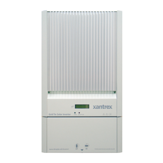
- Page 1 Grid Tie Solar Inverter GT2.5-NA GT3.0-NA GT3.3-NA Owner’s Manual Xantrex Grid Tie Solar Inverter http://www.wholesalesolar.com/inverters.html...
- Page 2 http://www.wholesalesolar.com/inverters.html http://www.wholesalesolar.com/inverters.html...
- Page 3 http://www.wholesalesolar.com/inverters.html Xantrex Grid Tie Solar Inverter Owner’s Manual http://www.wholesalesolar.com/inverters.html...
- Page 4 About Xantrex Xantrex Technology Inc. is a world-leading supplier of advanced power electronics and controls with products from 50 watt mobile units to one MW utility-scale systems for wind, solar, batteries, fuel cells, microturbines, and backup power applications in both grid-connected and stand-alone systems. Xantrex products include inverters, battery chargers, programmable power supplies, and variable speed drives that convert, supply, control, clean, and distribute electrical power.
-
Page 5: About This Manual
http://www.wholesalesolar.com/inverters.html About This Manual The purpose of this Owner’s Manual is to provide explanations and procedures for installing, operating, maintaining, and troubleshooting the Xantrex Grid Tie Solar Inverter™. Scope The manual provides safety guidelines, detailed planning and setup information. It provides procedures for installing the inverter and information about operating and troubleshooting the unit. -
Page 6: Conventions Used
http://www.wholesalesolar.com/inverters.html About This Manual Conventions Used The following conventions are used in this guide. WARNING Warnings identify conditions that could result in personal injury or loss of life. CAUTION Cautions identify conditions or practices that could result in damage to the unit or other equipment. - Page 7 About This Manual Related Information You can find more information about Xantrex Technology Inc. as well as its products and services at www.xantrex.com. 975-0245-01-01 http://www.wholesalesolar.com/inverters.html...
- Page 8 http://www.wholesalesolar.com/inverters.html http://www.wholesalesolar.com/inverters.html...
-
Page 9: Important Safety Instructions
http://www.wholesalesolar.com/inverters.html Important Safety Instructions SAVE THESE INSTRUCTIONS—This manual contains important instructions that shall be followed during the installation and maintenance of the Xantrex Grid Tie Solar Inverter. 1. Before installing and using the GT Inverter, read all instructions and cautionary markings on the inverter, wiring box, and all appropriate sections of this guide. -
Page 10: Regulatory Compliance
http://www.wholesalesolar.com/inverters.html Safety Regulatory Compliance The GT Inverter has complete on-board over-current, over-temperature and anti-islanding protection, and meets U.S., Canadian and international safety operating standards and code requirements: • UL 1741 1st Edition – Standard for Inverters, Converters, and Controllers for Use in Independent Power Systems •... -
Page 11: Verification And Commissioning Test
No changes to these settings can be made in the field by the user. Only authorized personnel with the utility’s permission may change these settings. Contact Xantrex Technology to gain permission and the procedure/equipment to make these changes. - Page 12 http://www.wholesalesolar.com/inverters.html http://www.wholesalesolar.com/inverters.html...
-
Page 13: Table Of Contents
http://www.wholesalesolar.com/inverters.html Contents Important Safety Instructions Regulatory Compliance - - - - - - - - - - - - - - - - - - - - - - - - - - - - - - - - - - - - - - - - - - - - - - - - - - viii FCC Information to the User - - - - - - - - - - - - - - - - - - - - - - - - - - - - - - - - - - - - - - - - - - - - - - - viii Verification and Commissioning Test - - - - - - - - - - - - - - - - - - - - - - - - - - - - - - - - - - - - - - - - - - ix 1 Introduction... - Page 14 http://www.wholesalesolar.com/inverters.html Contents Connecting Multiple Inverters - - - - - - - - - - - - - - - - - - - - - - - - - - - - - - - - - - - - - - - - - - - - - 3–9 DC and AC Wiring for Multiple Inverters - - - - - - - - - - - - - - - - - - - - - - - - - - - - - - - - - - -3–10 Communications Wiring for Multiple Inverters - - - - - - - - - - - - - - - - - - - - - - - - - - - - - - - - - 3–12 Xanbus Network Technology - - - - - - - - - - - - - - - - - - - - - - - - - - - - - - - - - - - - - - - - - - -3–12...
- Page 15 http://www.wholesalesolar.com/inverters.html Contents A Specifications Electrical Specifications - - - - - - - - - - - - - - - - - - - - - - - - - - - - - - - - - - - - - - - - - - - - - - - - - A–2 Input - - - - - - - - - - - - - - - - - - - - - - - - - - - - - - - - - - - - - - - - - - - - - - - - - - - - - - - - - - - -A–2 Output - - - - - - - - - - - - - - - - - - - - - - - - - - - - - - - - - - - - - - - - - - - - - - - - - - - - - - - - - - -A–2 Adjustable Disconnect Settings - - - - - - - - - - - - - - - - - - - - - - - - - - - - - - - - - - - - - - - - - -A–3...
- Page 16 http://www.wholesalesolar.com/inverters.html http://www.wholesalesolar.com/inverters.html...
- Page 17 http://www.wholesalesolar.com/inverters.html Figures Figure 1-1 Basic System Overview - - - - - - - - - - - - - - - - - - - - - - - - - - - - - - - - - - - - - - - - - - - - 1–2 Figure 1-2 Main Features of the GT Inverter- - - - - - - - - - - - - - - - - - - - - - - - - - - - - - - - - - - - - - 1–4 Figure 1-3...
- Page 18 http://www.wholesalesolar.com/inverters.html http://www.wholesalesolar.com/inverters.html...
- Page 19 http://www.wholesalesolar.com/inverters.html Tables Table 2-1 MPPT Operational Window - - - - - - - - - - - - - - - - - - - - - - - - - - - - - - - - - - - - - - - - - 2–6 Table 2-2 Inverter Clearance Requirements - - - - - - - - - - - - - - - - - - - - - - - - - - - - - - - - - - - - - 2–18 Table 3-1...
- Page 20 http://www.wholesalesolar.com/inverters.html xviii http://www.wholesalesolar.com/inverters.html...
-
Page 21: Introduction
http://www.wholesalesolar.com/inverters.html Introduction Chapter 1, “Introduction”, contains information about the features and functions of the Xantrex Grid Tie Solar Inverter. The topics in this chapter are organized as follows: • “Standard Features” on page 1–3 • “Safety and Standards” on page 1–6 http://www.wholesalesolar.com/inverters.html... -
Page 22: About The Xantrex Grid Tie Solar Inverter
http://www.wholesalesolar.com/inverters.html Introduction About the Xantrex Grid Tie Solar Inverter The Xantrex Grid Tie Solar Inverter (GT Inverter) is designed to convert solar electric (photovoltaic or PV) power into utility-grade electricity that can be used by the home or sold to the local power company. Installing the GT Inverter consists of mounting it to the wall and connecting the DC input to a PV array and the AC output to the utility. -
Page 23: Standard Features
http://www.wholesalesolar.com/inverters.html About the Xantrex Grid Tie Solar Inverter PV compatibility The GT Inverter is designed to take advantage of solar modules configured as high voltage PV string arrays—single crystalline, poly crystalline, or thin film—with a 195 to 550 Vdc input voltage Maximum Power Point range. Maximum Power The GT Inverter uses Xantrex proprietary Maximum Power Point Tracking Point Tracking... -
Page 24: Front Panel Features
http://www.wholesalesolar.com/inverters.html Introduction Front Panel Features Heat Sink LED Indicator Lights Grid Tie Solar Inverter Wiring/Disconnect Box DC/AC Disconnect Switch Mounting Slots Figure 1-2 Main Features of the GT Inverter Wiring/Disconnect Box The wiring/disconnect box is standard for all North American models of the GT Inverter. -
Page 25: Figure 1-3 Wiring Box And Removable Inverter
http://www.wholesalesolar.com/inverters.html About the Xantrex Grid Tie Solar Inverter wiring/disconnect box is an NEMA 3R enclosure to allow outdoor installation and is clearly marked as a PV system disconnect. The lockable switch meets NEC section 690 requirements as a means of disconnect. AC Disconnect In some jurisdictions, where the local utility requires that the AC disconnect be capable of being locked in the open position by its service personnel, this... -
Page 26: Safety And Standards
http://www.wholesalesolar.com/inverters.html Introduction Safety and Standards The GT Inverter has complete on-board over-current, over-temperature and anti- islanding protection, and meets U.S. and Canadian safety operating standards and code requirements: • UL 1741 – Standard for Inverters, Converters, and Controllers for Use in Independent Power Systems •... -
Page 27: Installation
http://www.wholesalesolar.com/inverters.html Installation Chapter 2, “Installation”, provides information about planning for and installing the GT Inverter. It contains information to help you plan wire routes, AC and DC connections, and find a suitable location for installation. It also discusses requirements for grounding the GT Inverter and your PV array. -
Page 28: Installation Options
http://www.wholesalesolar.com/inverters.html Installation Installation Options The GT Inverter may be installed as a single inverter for a single PV array of one or two PV strings, or in a multiple inverter configuration for multiple PV arrays (see Figure 2-1 for diagrams of both options). Single Inverter Installation In this configuration, a single inverter collects the harvested solar energy and routes the power to the main utility service panel to be used by the loads. -
Page 29: Figure 2-1 Installation Options Overview
http://www.wholesalesolar.com/inverters.html Planning the Installation Utility Grid Single Inverter Installation Xantrex Utility Meter GT Inverter Main Utility Service Panel Photovoltaic Panels - PV Array Surplus power routed to Utility Grid PV String #1 Harvested solar energy Loads converted to AC Grid Tie Inv erter PV String #2 Power routed to loads... -
Page 30: Inverter Location
http://www.wholesalesolar.com/inverters.html Installation Inverter Location WARNING: Burn hazard Do not install in a location where people can accidentally come into contact with the front of the inverter. High temperatures can be present on the face of the inverter, causing a potential burn hazard. In extreme conditions, the GT Inverter chassis can reach temperatures over 70°... -
Page 31: Pv Array Requirements
http://www.wholesalesolar.com/inverters.html Planning the Installation Debris free • Excessive debris (such as dust, leaves, and cobwebs) can accumulate on the unit, interfering with wiring connections and ventilation. Do not install in a location where debris can accumulate (under a tree, for example). PV Array Requirements WARNING: Shock hazard Whenever a PV array is exposed to sunlight, a shock hazard exists at the output wires or... -
Page 32: Table 2-1 Mppt Operational Window
http://www.wholesalesolar.com/inverters.html Installation Voltage and MPPT Requirements MPPT operational The MPPT software maximizes the output energy of solar arrays as long as the window operating voltage is within the MPPT operational window. Ensure that the PV array used in the system operates within the MPPT operational window. Effects of array voltages outside of the MPPT operational window are shown in Table 2-1. - Page 33 http://www.wholesalesolar.com/inverters.html Planning the Installation Guidelines for Matching PV Array Size to Xantrex Grid Tie Solar Inverter Input For determining the number of panels required in the PV string (panels connected in series), you must ensure that the following requirements are met: 1.
-
Page 34: Grounding Requirements
http://www.wholesalesolar.com/inverters.html Installation Grounding Requirements WARNING: Shock hazard The GT Inverter must be grounded by connection to a grounded permanent wiring system. AC Grounding North America The GT Inverter must be connected to a grounded, permanent wiring system via the GT Inverter ground bar. See Figure 2-2 for the location of the GT Inverter ground bar. -
Page 35: Figure 2-2 Basic Grounding Overview
http://www.wholesalesolar.com/inverters.html Planning the Installation Lightning Protection Reduce the risk of lightning damage by using a single-point grounding system. In this system, all ground lines terminate at the same point—the primary earth ground. This point normally is the main utility ground installed by the utility company to provide a ground for the house wiring (see Figure 2-4). -
Page 36: Figure 2-3 Long Distance Grounding Overview
http://www.wholesalesolar.com/inverters.html Installation PV Array When the distance between the PV Array and the GT Inverter is greater than 30 m (100 ft), the array should have its own earth ground, which should be connected to the Primary Earth Ground by a buried wire. PV String #1 Check your local codes for grounding requirements. -
Page 37: Routing The Wires
http://www.wholesalesolar.com/inverters.html Planning the Installation PV Array Main Utility Service Panel PV String #1 NEUTRAL Neutral PV String #2 -to- Ground Bond GROUND Xantrex GT Inverter Wiring Box AC Ground GND bar Primary Earth DC/AC Disconnect Switch Ground DC Ground Figure 2-4 Grounding With Extra Lightning Protection Overview Routing the Wires Typical Determine all wire routes to and from the GT Inverter. -
Page 38: Preparing For The Installation
http://www.wholesalesolar.com/inverters.html Installation WARNING: Shock hazard Check for existing electrical or plumbing prior to drilling holes in the walls. Conduit Pre-plan the wire and conduit runs. Dual knockouts for 35 mm (1 3/8 inch) or holes/knockouts 27 mm (1 inch) conduit holes are located on the bottom and back of the wiring box—four dual knockouts in total. -
Page 39: Wiring
http://www.wholesalesolar.com/inverters.html Preparing for the Installation Wiring Wire size and length will be determined by the location of each component and their relative distance to each other. Wire sizes may also be affected by whether or not conduit is used. Recommended wire Strip all wires 9 mm (3/8 inch). -
Page 40: Other Materials Needed
http://www.wholesalesolar.com/inverters.html Installation WARNING: Shock hazard Do not attempt to service the ground fault protection fuse yourself. This should only be done by qualified service personnel, such as certified electricians or technicians. Other Materials Needed • Mounting support material, such as plywood or poles •... -
Page 41: Mounting The Inverter
http://www.wholesalesolar.com/inverters.html Mounting the Inverter Mounting the Inverter Overview WARNING: Fire, Shock and Energy Hazards Before installing the GT Inverter, read all instructions and cautionary markings located in this manual, on the PV array, and on the main service panel. General installation There are four main steps in the installation of the GT Inverter: steps 1. -
Page 42: Preparing To Mount The Unit
http://www.wholesalesolar.com/inverters.html Installation In this chapter only the first step, mounting the inverter and installing accessories, is described. Mounting steps Instructions for mounting the GT Inverter are described in the following sections: • “Preparing to Mount the Unit” on page 2–16 •... -
Page 43: Installing The Mounting Bracket
http://www.wholesalesolar.com/inverters.html Mounting the Inverter 13.7 Front view Side view 69.9 72.6 2.7 cm (1") conduit holes with threaded caps, on both sides Dual 3.5 cm or 2.7 cm " or 1") knockouts (on back panel). 40.3 Dual 3.5 cm or 2.7 cm "... -
Page 44: Figure 2-8 Mounting Bracket And Gt Inverter
http://www.wholesalesolar.com/inverters.html Installation Mounting bracket Back side of the inverter 25.3 (10) Rectangular slots × 25: 0.8 × 3 (5/16 × 1 3/16 Mounting flanges Mounting flanges All measurements in cm (inches). Mounting slots for securing the inverter Figure 2-8 Mounting Bracket and GT Inverter Clearance Requirements For optimal and safe operation, ensure there is adequate clearance around the inverter. - Page 45 http://www.wholesalesolar.com/inverters.html Mounting the Inverter WARNING: Shock hazard Before drilling holes to mount the GT Inverter, ensure there are no electrical wires or plumbing in this area. WARNING: Personal injury The GT Inverter weighs approximately 20 kg (45 lbs.). Always use proper lifting techniques during installation to prevent personal injury.
-
Page 46: Figure 2-9 Examples Of Mounting On A Pole Or Rails
http://www.wholesalesolar.com/inverters.html Installation Mounting on Poles or Rails To mount the unit using poles: 1. Ensure that poles or rails are securely assembled in place. If using horizontal rails, three rails are required: two for the mounting bracket and a third for securing the bottom edge of the inverter wiring box (see Figure 2-9). -
Page 47: Figure 2-10 Installing The Mounting Bracket Using Plywood Support
http://www.wholesalesolar.com/inverters.html Mounting the Inverter Mounting on Wallboard, Siding or Concrete To mount the GT Inverter to wallboard, siding, or concrete: 1. Locate the area where the GT Inverter is to be installed. 2. Install backing support material if required. See Figure 2-10. 40.6 (16) 34 (13.5) O.C. -
Page 48: Mounting The Inverter On The Bracket
http://www.wholesalesolar.com/inverters.html Installation Mounting the Inverter on the Bracket Mounting a Single Inverter To mount the inverter on the mounting bracket: 1. Place the GT Inverter’s mounting hooks, located on the back of the enclosure, over the bracket and ensure the inverter is seated properly, as shown in Figure 2-11. - Page 49 http://www.wholesalesolar.com/inverters.html Mounting the Inverter Mounting Multiple Inverters As shown in Figure 2-10, inverters can be mounted side by side on wallboard or a plywood support. Conduit nipples should be installed on one side of the first inverter before mounting on the bracket. Ensure that the sealing ring is located on the conduit nipple between inverters, i.e., on the outside of the wiring box.
- Page 50 http://www.wholesalesolar.com/inverters.html 2–24 http://www.wholesalesolar.com/inverters.html...
-
Page 51: Wiring The Inverter
http://www.wholesalesolar.com/inverters.html Wiring the Inverter Chapter 3, “Wiring the Inverter”, provides procedures for making DC and AC wiring connections, and grounding the GT Inverter and the PV array. Instructions for wiring multiple inverters are also provided. The topics in this chapter are organized as follows: •... -
Page 52: Accessing The Wiring Terminals
http://www.wholesalesolar.com/inverters.html Wiring the Inverter Accessing the Wiring Terminals You must remove the GT Inverter wiring box cover to access the terminal blocks, ground bar and communications ports (for connecting multiple inverters). To remove the wiring box cover: 1. Using a Phillips screwdriver, remove the two screws on the bottom side of the wiring box and set in a safe place (see Figure 3-1 for location of screws). -
Page 53: Figure 3-2 Ac And Dc Terminal Block Location In The Wiring Box
http://www.wholesalesolar.com/inverters.html Accessing the Wiring Terminals AC Terminals for DC Terminals connecting to main for connecting utility service panel PV strings DC/AC Disconnect Switch Figure 3-2 AC and DC Terminal Block Location in the Wiring Box 975-0245-01-01 3–3 http://www.wholesalesolar.com/inverters.html... -
Page 54: Connecting The Dc Wiring
http://www.wholesalesolar.com/inverters.html Wiring the Inverter Connecting the DC Wiring WARNING: Shock hazard Whenever a PV array is exposed to sunlight, a shock hazard exists at the output wires or exposed terminals. To reduce the risk of shock during installation, cover the array with an opaque (dark) material and ensure that the DC/AC Disconnect Switch is set to OFF before commencing any wiring. -
Page 55: Table 3-1 Torque Values For Wires
http://www.wholesalesolar.com/inverters.html Connecting the DC Wiring The following procedure is illustrated in Figure 3-4. If there is more than one PV string, label the positive and negative wire pairs appropriately (for example: PV1-String #1 POS, PV1-String #1 NEG, PV1-String #1 GND, PV1-String #2 POS, etc.). -
Page 56: Figure 3-4 Dc Connections For Multiple Pv Strings
http://www.wholesalesolar.com/inverters.html Wiring the Inverter PV1 String #2 PV String #2 PV Array 1 – – PV1 String #1 PV String #1 Xantrex GT Inverter Wiring Box GND bar DC/AC Disconnect Switch DC Ground if required by AHJ Figure 3-4 DC Connections for Multiple PV Strings Important: Depending upon installation and local codes, fusing and/or a combiner box may be required. -
Page 57: Connecting The Ac Wiring
http://www.wholesalesolar.com/inverters.html Connecting the AC Wiring Connecting the AC Wiring WARNING: Shock hazard AC utility wiring to the GT Inverter unit is performed directly at the main breaker panel. This should be done only by a qualified installer or electrician. WARNING: Shock hazard Before wiring the GT Inverter, ensure the main breaker in the primary utility breaker box is switched OFF. -
Page 58: Figure 3-5 Ac Connections From Gt Inverter To Utility Service Panel
http://www.wholesalesolar.com/inverters.html Wiring the Inverter To wire the main utility service panel to the GT Inverter: 1. Install conduit from the main utility service panel to the wiring/disconnect box of the GT Inverter. Run the two HOT wires (L1 and L2) and ground wire from the service panel through the conduit and into the inverter wiring box. -
Page 59: Connecting Multiple Inverters
http://www.wholesalesolar.com/inverters.html Connecting Multiple Inverters Connecting Multiple Inverters For installations with multiple GT Inverters, separate solar arrays are required for each unit. The output of each GT Inverter feeds a separate dual-pole 20-Amp circuit breaker (L1 and L2) in the main utility service panel. For such installations, complete the wiring and perform the commissioning procedure for each inverter one at a time. -
Page 60: Dc And Ac Wiring For Multiple Inverters
http://www.wholesalesolar.com/inverters.html Wiring the Inverter DC and AC Wiring for Multiple Inverters The following procedures are illustrated in Figure 3-7. The illustration and instructions assume only two inverters, but in fact up to ten inverters can be installed and networked together. If there will be more than one PV array, label the positive and negative wire pairs appropriately (for example: PV1 POS, PV1 NEG, PV1 GND, PV2 POS, etc.). -
Page 61: Figure 3-7 Dc And Ac Wiring With Multiple Gt Inverters
http://www.wholesalesolar.com/inverters.html Connecting Multiple Inverters PV Array #2 (PV2) PV Array #2 Utility Grid – PV Array #1 (PV1) PV Array #1 L1 L2 Neutral – Utility Meter L1 L2 Neutral Main Utility Service Panel Xantrex GT Inverter #1 Wiring Box NEUTRAL GND bar Neutral-... -
Page 62: Communications Wiring For Multiple Inverters
http://www.wholesalesolar.com/inverters.html Wiring the Inverter Communications Wiring for Multiple Inverters Communications wiring between multiple GT Inverters allows information about each inverter and its associated PV array to be communicated between all of the inverters in the system. Information about the entire system can be displayed on any inverter LCD in the system. -
Page 63: Figure 3-9 Male Network Terminator
http://www.wholesalesolar.com/inverters.html Communications Wiring for Multiple Inverters Terminators Male network terminators (Figure 3-9) are required at both ends of the network to ensure the communication signal quality on the network. Figure 3-9 Male Network Terminator GT Inverter Xanbus Two RJ45 ports are provided in the GT Inverter, accessible from the wiring box. Ports See Figure 3-10 for the location of these ports. -
Page 64: Figure 3-11 Rj45 Connector
http://www.wholesalesolar.com/inverters.html Wiring the Inverter Cabling Requirements CAUTION: Equipment damage Do not use crossover cable in a Xanbus system. The network uses Category 5 (CAT 5) cable, a standard cable available from any computer supply store. The cable consists of eight conductors in four twisted pairs with an RJ45 modular connector wired to the T568A standard. -
Page 65: Guidelines For Routing The Network Cables
http://www.wholesalesolar.com/inverters.html Communications Wiring for Multiple Inverters Purchasing Network Components Consult with your system designer to determine what network components will be needed for your specific installation. Table 3-3 provides a partial list of network components and part numbers. Pre-made cables are available in standard lengths from 3 feet to 75 feet. -
Page 66: Connecting Network Cable Between Multiple Inverters
http://www.wholesalesolar.com/inverters.html Wiring the Inverter Connecting Network Cable Between Multiple Inverters WARNING: Shock hazard If the inverter is already installed and operational, turn OFF the breaker switches in the main utility service panel and the DC/AC Disconnect switch on the inverter wiring box before performing this procedure. -
Page 67: Figure 3-12 Communications Wiring For Multiple Gt Inverters
http://www.wholesalesolar.com/inverters.html Communications Wiring for Multiple Inverters PV Array #2 (PV2) PV Array #2 – PV Array #1 (PV1) PV Array #1 – Network cable in separate conduit from AC and DC wiring. Xantrex GT Inverter #2 Xantrex GT Inverter #1 Wiring Box Wiring Box Male Terminator... -
Page 68: Communications Wiring For Monitoring A Single Inverter
http://www.wholesalesolar.com/inverters.html Wiring the Inverter Communications Wiring for Monitoring a Single Inverter You can view GT Inverter operational data on a personal computer using the Xantrex GT Solar Inverter Viewer (“GT-View”), which you can download free of charge at www.xantrex.com. To use GT-View, you must connect your computer’s serial port to the GT Inverter RS-232 port (see Figure 3-10). -
Page 69: Figure 3-13 Gt-View Display
http://www.wholesalesolar.com/inverters.html Communications Wiring for Multiple Inverters GT-View displays operational data such as power output in AC watts, lifetime energy produced, and inverter temperature. Data is updated every two seconds (default setting). Figure 3-13 GT-View Display To configure GT-View, right click anywhere in the GT-View display and select Settings from the pop-up menu. - Page 70 http://www.wholesalesolar.com/inverters.html 3–20 http://www.wholesalesolar.com/inverters.html...
-
Page 71: Starting The Inverter
http://www.wholesalesolar.com/inverters.html Starting the Inverter Chapter 4, “Starting the Inverter”, contains information on starting up the Xantrex Grid Tie Solar Inverter and performing a Functional Test. The topics in this chapter are organized as follows: • “Startup Procedure” on page 4–2 •... -
Page 72: Startup Procedure
http://www.wholesalesolar.com/inverters.html Starting the Inverter Startup Procedure Starting up the GT Inverter requires several steps. You will need to: 1. Ensure the DC/AC Disconnect switch is in the OFF position (see Figure 4-1). 2. Check the PV array DC voltage (see procedure below). 3. -
Page 73: Replacing The Wiring/Disconnect Box Cover
http://www.wholesalesolar.com/inverters.html Replacing the Wiring/Disconnect Box Cover Replacing the Wiring/Disconnect Box Cover After performing the voltage checks, replace all covers that were removed during installation and startup. WARNING: Shock hazard Before reattaching covers, turn OFF the breaker switches in the main utility service panel and the DC/AC Disconnect switch on the GT Inverter. -
Page 74: Starting Up The Gt Inverter
http://www.wholesalesolar.com/inverters.html Starting the Inverter Starting up the GT Inverter To start up the inverter: 1. Switch the DC/AC Disconnect switch to the ON position (see Figure 4-1). 2. Check the GT Inverter LCD. The startup screens (see Table 5-1 on page 5–3) should appear for five seconds each, and then the “Reconnecting in sss seconds”... -
Page 75: Figure 4-2 Commissioning Sequence For Multiple Inverters
http://www.wholesalesolar.com/inverters.html Replacing the Wiring/Disconnect Box Cover 4. After the input current has risen above 1 A, if the inverter is still operating normally, switch off the inverter by turning the DC/AC disconnect switch to the OFF position. Proceed to step 5. If the inverter stops operating, turn the unit off, remove DC power, and have a certified electrician or technician inspect the ground fault protection fuse. -
Page 76: Disconnect Test
http://www.wholesalesolar.com/inverters.html Starting the Inverter Disconnect Test The disconnect test is designed to verify correct operation of the GT Inverter both on initial operation and periodically through its life as required by the utilities. This test ensures that the Xantrex Grid Tie Solar Inverter does not send electricity to the utility grid when the local utility has shut off the grid for repairs, or when the utility wiring is damaged. -
Page 77: Monitoring The Inverter
http://www.wholesalesolar.com/inverters.html Monitoring the Inverter Chapter 5, “Monitoring the Inverter”, contains information for understanding the LCD screens and the LED indicators. The topics in this chapter are organized as follows: • “Monitoring the Front Panel Display” on page 5–2 • “Front Panel Display Screens and What They Mean” on page 5–3 •... -
Page 78: Monitoring The Front Panel Display
http://www.wholesalesolar.com/inverters.html Monitoring the Inverter Monitoring the Front Panel Display During startup During startup, the inverter’s front panel LCD (see Figure 5-1) shows the first three screens described in Table 5-1, “Startup Screens on GT Inverter Front Panel Display” on page 5–3. During waiting When the 305 second protection timer begins, the inverter displays “Reconnecting period... -
Page 79: Front Panel Display Screens And What They Mean
http://www.wholesalesolar.com/inverters.html Front Panel Display Screens and What They Mean Front Panel Display Screens and What They Mean The front panel display shows different message screens during different modes of operation (Startup, Normal, Offline, and Fault). All single units display a basic set of message screens;... -
Page 80: Table 5-2 Normal Operation Default Screen
http://www.wholesalesolar.com/inverters.html Monitoring the Inverter Table 5-2 Normal Operation Default Screen Display Description System 2000W Power being produced by the system now. Today 9.875kWh Cumulative energy produced by the system today. If there is sufficient energy from the PV array, this screen is displayed continuously while the system is operating normally. -
Page 81: Offline Mode
http://www.wholesalesolar.com/inverters.html Front Panel Display Screens and What They Mean * In a multiple unit system with network cables properly installed, the system values displayed are for the entire system. For example, in a two-inverter system, if inverter #1 is producing 1500 W and inverter #2 is producing 2000 W, both inverters display a total system power of 3500 W. -
Page 82: Table 5-6 Offline Mode Screens For All Gt Inverter Units
http://www.wholesalesolar.com/inverters.html Monitoring the Inverter These message screens are common to all GT Inverter systems, no matter how many units are installed. If you continue to tap the unit, then the LCD will continue to cycle through all of the available offline mode screens. Table 5-6 Offline Mode Screens for All GT Inverter Units Display* Description... -
Page 83: Fault Mode
http://www.wholesalesolar.com/inverters.html Front Panel Display Screens and What They Mean Fault Mode When a fault state is detected, the appropriate fault message appears on the front panel display at the next screen refresh (i.e., within 2 seconds). The GT Inverter fault message screens are shown in Table 5-8. Fault Mode causes These message screens only appear when there is a fault, and then flash alternately with the Inverter Offline default screen (Table 5-5) until the fault is... - Page 84 http://www.wholesalesolar.com/inverters.html Monitoring the Inverter Additional Fault Additional message screens can be viewed in fault mode by tapping the Xantrex messages for all logo near the LCD. Each additional tap displays the next screen in the order systems shown in Table 5-9. Table 5-9 Additional Fault Mode Screens Display* Description...
-
Page 85: Special Screens
http://www.wholesalesolar.com/inverters.html Front Panel Display Screens and What They Mean Special Screens Special message screens are displayed in specific situations that are not considered fault situations. They can appear in any mode of operation. These screens are described in Table 5-10. Table 5-10 Special Message Screens Display Description... -
Page 86: Status Indicator Lights
http://www.wholesalesolar.com/inverters.html Monitoring the Inverter Status Indicator Lights The GT Inverter is equipped with two status indicator lights (LEDs) located below the front panel LCD (Figure 5-2). These LEDs indicate the inverter’s current status (Table 5-11) and assist in troubleshooting the performance of the unit. Only one indicator light will be lit at any time. -
Page 87: Maintenance And Troubleshooting
http://www.wholesalesolar.com/inverters.html Maintenance and Troubleshooting Chapter 6, “Maintenance and Troubleshooting”, contains information about how to provide general maintenance for the Xantrex Grid Tie Solar Inverter. It also provides information about troubleshooting the unit. The topics in this chapter are organized as follows: •... -
Page 88: Factors Affecting Gt Inverter Performance
http://www.wholesalesolar.com/inverters.html Maintenance and Troubleshooting Factors Affecting GT Inverter Performance This section describes several factors that will affect the amount of power that a properly installed and operating GT Inverter can produce. PV Array Factors PV array ratings PV arrays are rated at ideal factory conditions, such as specified illumination (1000 W/m ), spectrum of the light and specified temperature (25°C / 77°F), which seldom reflect real-world installations. -
Page 89: Other Factors
http://www.wholesalesolar.com/inverters.html Performing General Maintenance Other Factors Other factors that contribute to system losses are: • Dust or dirt on the array • Fog or smog • Mismatched PV array modules, with slight inconsistencies in performance from one module to another. •... -
Page 90: Replacing The Ground Fault Protection Fuse
http://www.wholesalesolar.com/inverters.html Maintenance and Troubleshooting Replacing the Ground Fault Protection Fuse WARNING: Shock and fire hazard Fuses should only be replaced by qualified service personnel, such as a certified electrician or technician. For continued protection against risk of fire, replace only with same type and ratings of fuse. -
Page 91: Figure 6-1 Location Of Fuse, Front Panel Cover Removed
http://www.wholesalesolar.com/inverters.html Replacing Parts 5. Replace the wiring/disconnect box cover. Ground Fault Protection Ground Fault Fuse (“-POS” models) Protection Fuse Figure 6-1 Location of Fuse, Front Panel Cover Removed Figure 6-2 Display Front Panel Assembly 975-0245-01-01 6–5 http://www.wholesalesolar.com/inverters.html... -
Page 92: Replacing The Inverter
http://www.wholesalesolar.com/inverters.html Maintenance and Troubleshooting Replacing the Inverter If your GT Inverter requires servicing, you can replace it with another inverter, leaving the existing wiring box in place. This means that you do not have to disturb wiring connections in the wiring/disconnect box. However, you do have to disconnect wiring between the inverter and the wiring/disconnect box. -
Page 93: Figure 6-3 Wiring/Disconnect Box And Removable Inverter
http://www.wholesalesolar.com/inverters.html Replacing Parts 4. Disconnect the remaining AC, DC and network cables between the inverter and the wiring box, inside the inverter. Cap all disconnected AC and DC wires with wire nuts. 5. Inside the inverter, remove the four nuts attaching the wiring box to the inverter. -
Page 94: Figure 6-4 Inverter And Wiring/Disconnect Box Sections
http://www.wholesalesolar.com/inverters.html Maintenance and Troubleshooting Back view Top mounting hook goes over wall-mounted bracket Inverter Lower flange goes behind wiring/disconnect box Wiring/ disconnect box permanently mounted to bracket Figure 6-4 Inverter and Wiring/Disconnect Box Sections To replace the inverter on the wiring box: 1. -
Page 95: Identifying Error/Fault Conditions And Solutions
http://www.wholesalesolar.com/inverters.html Identifying Error/Fault Conditions and Solutions Identifying Error/Fault Conditions and Solutions Most error or fault conditions will be identified by fault message screens on the GT Inverter front panel LCD. These are described in the “Fault Mode” section on page 5–7 of this manual. Most of these fault conditions are self-correcting and require no user action to remedy. - Page 96 http://www.wholesalesolar.com/inverters.html 6–10 http://www.wholesalesolar.com/inverters.html...
-
Page 97: Specifications
http://www.wholesalesolar.com/inverters.html Specifications Appendix A, “Specifications”, contains information about the electrical and environmental specifications of the Xantrex Grid Tie Solar Inverter. The topics in this appendix are organized as follows: • “Electrical Specifications” on page A–2 • “Environmental Specifications” on page A–6 •... -
Page 98: Electrical Specifications
Up to 3300 W Up to 3600 W Reverse polarity protection Short circuit diode Ground fault protection GF detection, I > 1 A Output Model numbers GT2.5-NA-DS-240 GT3.3-NA-DS-240 GT3.3-NA-DS-208 GT2.5-NA-DS-240-POS GT3.0-NA-DS-240 GT3.3-NA-DS-240-POS GT3.3-NA-DS-208-POS Maximum output power 2500 W AC 3000 W AC... -
Page 99: Adjustable Disconnect Settings
http://www.wholesalesolar.com/inverters.html Electrical Specifications Adjustable Disconnect Settings Islanding protection is an essential safety feature that ensures no person working on the grid is harmed by a distributed energy source. Default software settings are programmed into each GT Inverter at the factory to ensure it does not island according to relevant safety regulations (UL1741, etc.). -
Page 100: Figure A-1 Output Power Vs. Ambient Temperature At Various Dc Voltages
http://www.wholesalesolar.com/inverters.html Specifications Output Power Versus Ambient Temperature Once the heat sink on the inverter reaches a maximum temperature limit, the GT Inverter reduces its energy output to ensure maximum component ratings are not exceeded. GT Power Derating Curve 3500.00 GT3.3 GT3.0 3000.00 GT2.5... -
Page 101: Efficiency
http://www.wholesalesolar.com/inverters.html Electrical Specifications Efficiency GT 2.5 240 V GT 3.0 240 V GT 3.3 240 V GT 3.3 208 V Maximum efficiency 94.8% 95.3% 95.3% 94.7% CEC efficiency 94.5% 94.5% Night-time tare loss GRID TIE SOLAR INVERTER Typical Efficiency [%] - Efficiency versus Output Power - 1000 1500... -
Page 102: Environmental Specifications
http://www.wholesalesolar.com/inverters.html Specifications Environmental Specifications Operating temperature range -25° to +65° C (-13° to +149° F) Storage temperature range -40° to +85° C (-40° to +185° F) Power derating See Figure A-1 on page A–4 Tolerable relative humidity limit Operating: 100% condensing Storage: <95%, non-condensing User Display Type... -
Page 103: Warranty And Return Information
Warranty What does this warranty cover? This Limited Warranty is provided by Xantrex Technology, Inc. ("Xantrex") and covers defects in workmanship and materials in your Xantrex Grid Tie Solar Inverter. This warranty period lasts for five years from the date of purchase at the point of sale to you, the original end user customer. You require proof of purchase to make warranty claims. - Page 104 http://www.wholesalesolar.com/inverters.html Warranty and Return What does this warranty not cover? This Limited Warranty does not cover normal wear and tear of the product or costs related to the removal, installation, or troubleshooting of the customer's electrical systems. This warranty does not apply to and Xantrex will not be responsible for any defect in or damage to: a) the product if it has been misused, neglected, improperly installed, physically damaged or altered, either inter- nally or externally, or damaged from improper use or use in an unsuitable environment;...
-
Page 105: Return Material Authorization Policy
Include the following: • The RMA number supplied by Xantrex Technology, Inc. clearly marked on the outside of the box. • A return address where the unit can be shipped. Post office boxes are not acceptable. -
Page 106: Information About Your System
http://www.wholesalesolar.com/inverters.html Warranty and Return Information About Your System As soon as you open your Xantrex Grid Tie Solar Inverter package, record the following information and be sure to keep your proof of purchase. Model Number _________________________________ Serial Number _________________________________ Purchased From _________________________________ Purchase Date _________________________________... -
Page 107: Index
http://www.wholesalesolar.com/inverters.html Index 5–5 offline mode messages 5–3 reading messages abbreviations and acronyms 5–9 special messages 2–13 AC circuit breaker requirements 5–3 startup messages 2–8 AC grounding requirements 6–5 fuse, location of ground fault protection A–2 AC output voltage ratings 2–13 fuses and circuit breakers 4–2 AC utility voltage... - Page 108 http://www.wholesalesolar.com/inverters.html Index 3–10 DC wiring 1–2 photovoltaic (PV) power LEDs, status LEDs A–6 power derating 2–9 lightning protection 2–12 preparing for installation 2–8 long-distance grounding WA–4 proof of purchase WA–4 purchase date PV arrays 6–3 6–2 maintenance, general angle of the sun 4–2 maximum power point tracking, MPPT...
- Page 109 http://www.wholesalesolar.com/inverters.html Index 2–4 range for locating Xantrex GT Inverter 3–3 terminal blocks in wiring box 3–13 terminators, male network A–4 thermal derating chart 3–5 torque values for wires 6–9 troubleshooting the GT Inverter voltmeter 4–2 measuring PV array DC at startup 4–2 measuring utility AC at startup warranty...
- Page 110 http://www.wholesalesolar.com/inverters.html IX-4 http://www.wholesalesolar.com/inverters.html...
- Page 111 http://www.wholesalesolar.com/inverters.html http://www.wholesalesolar.com/inverters.html...
- Page 112 Xantrex Technology Inc. 1 800 670 0707 Tel toll free NA 1 360 925 5097 Tel direct 1 360 925 5143 Fax direct customerservice@xantrex.com www.xantrex.com 975-0245-01-01 Printed in China http://www.wholesalesolar.com/inverters.html...
Need help?
Do you have a question about the GT2.5-NA and is the answer not in the manual?
Questions and answers