Table of Contents
Advertisement
Advertisement
Table of Contents

Related Manuals for Xantrex GT2.8-AU-QC-230


Summary of Contents for Xantrex GT2.8-AU-QC-230
- Page 1 GT2.8-AU-QC-230 GT5.0-AU-QC-230 Owner’s Manual Xantrex Grid Tie Solar Inverter...
- Page 3 Xantrex Grid Tie Solar Inverter Owner’s Manual...
- Page 4 Notice of Copyright Copyright © April 2009 Xantrex Technology Inc. No part of this document may be reproduced in any form or disclosed to third parties without the express written consent of: Xantrex Technology Inc.
-
Page 5: About This Manual
Audience Chapter 1 and Chapter 5 are intended for anyone who needs to operate the Xantrex Grid Tie Solar Inverter. Operators must be familiar with all the safety regulations pertaining to operating high-voltage equipment as dictated by local code. Operators must also have a complete understanding of this equipment’s features and functions. -
Page 6: Conventions Used
GT-View monitoring software. Chapter 4, “Starting the Inverter”, contains information on starting up the Xantrex Grid Tie Solar Inverter and performing a functional test. Chapter 5, “Monitoring the Inverter”, contains information for understanding the LCD screens and the LED indicators. -
Page 7: Symbols Used
DC and AC power and wait 30 minutes to allow internal voltages to reach safe levels. NOTE: there are no user-serviceable parts inside. Refer to the operating instructions. Related Information You can find more information about Xantrex Technology Inc. as well as its products and services at www.xantrex.com 975-0466-01-01... -
Page 9: Important Safety Instructions
Important Safety Instructions WARNING: Save these instructions This manual contains important safety and operating instructions. Read and keep this Owner’s Manual for future reference. WARNING: Limitations on use Do not use this GT Inverter in connection with life support systems, medical equipment, or where human life or medical property may be at stake. -
Page 10: Regulatory Compliance
Safety Regulatory Compliance The GT Inverter is compliant with the standards described below. • Safety: Regulatory Compliance Mark (RCM) based on compliance with AS/NZS 3100 Approval and test specification – General requirements for electrical equipment • Electromagnetic Compatibility (EMC): RCM mark based on compliance with: •... -
Page 11: Table Of Contents
About the Xantrex Grid Tie Solar Inverter - - - - - - - - - - - - - - - - - - - - - - - - - - - - - - - - - - - - - - 1–2... - Page 12 Contents Connecting Multiple Inverters - - - - - - - - - - - - - - - - - - - - - - - - - - - - - - - - - - - - - - - - - - - - - 3–6 Connecting the AC Wiring- - - - - - - - - - - - - - - - - - - - - - - - - - - - - - - - - - - - - - - - - - - - - - - - 3–7 Making AC Connections for the GT2.8-AU Model - - - - - - - - - - - - - - - - - - - - - - - - - - - - - 3–7 Making AC Connections for GT5.0-AU Model - - - - - - - - - - - - - - - - - - - - - - - - - - - - - - - 3–9...
- Page 13 Contents Environmental Specifications - - - - - - - - - - - - - - - - - - - - - - - - - - - - - - - - - - - - - - - - - - - - - -A–5 User Display - - - - - - - - - - - - - - - - - - - - - - - - - - - - - - - - - - - - - - - - - - - - - - - - - - - - - - -A–5 Display Accuracy - - - - - - - - - - - - - - - - - - - - - - - - - - - - - - - - - - - - - - - - - - - - - - - - - - - -A–5 Mechanical Specifications - - - - - - - - - - - - - - - - - - - - - - - - - - - - - - - - - - - - - - - - - - - - - - - -A–5...
- Page 14 Contents 975-0466-01-01...
- Page 15 Figures Figure 1-1 Basic System Overview - - - - - - - - - - - - - - - - - - - - - - - - - - - - - - - - - - - - - - - - - - - - 1–2 Figure 1-2 Main Features of the GT Inverter (GT2.8-AU Model Shown) - - - - - - - - - - - - - - - - - - 1–4 Figure 2-1...
- Page 17 Tables Table 2-1 MPPT Operational Window (GT2.8-AU) - - - - - - - - - - - - - - - - - - - - - - - - - - - - - - - - 2–6 Table 2-2 MPPT Operational Window (GT5.0-AU) - - - - - - - - - - - - - - - - - - - - - - - - - - - - - - - - 2–6 Table 2-3...
-
Page 19: Introduction
Chapter 1, “Introduction”, contains information about the features and functions of the Xantrex Grid Tie Solar Inverter. The topics in this chapter are organized as follows: • “About the Xantrex Grid Tie Solar Inverter” on page 1–2 • “Standard Features” on page 1–3... -
Page 20: About The Xantrex Grid Tie Solar Inverter
Introduction About the Xantrex Grid Tie Solar Inverter The Xantrex Grid Tie Solar Inverter (GT Inverter) is designed to convert solar electric (photovoltaic or PV) power into utility-grade electricity that can be used by the home or sold to the local power company. -
Page 21: Standard Features
195 to 550 Vdc output voltage Maximum Power Point range (240 to 550 Vdc for the GT5.0-AU model). Maximum Power The GT Inverter uses Xantrex proprietary Maximum Power Point Tracking Point Tracking (MPPT) technology to harvest the maximum amount of energy from the solar (MPPT) array. -
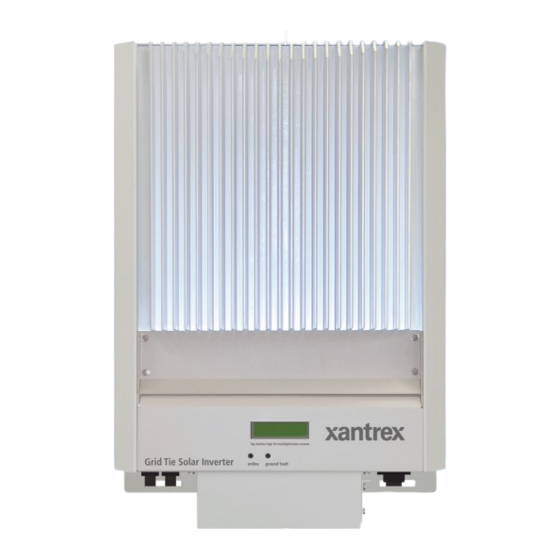
Page 22: Figure 1-2 Main Features Of The Gt Inverter (Gt2.8-Au Model Shown)
Introduction Heat sink LED indicator lights DC quick-connects AC connection Communication ports cover Mounting slots (five) Figure 1-2 Main Features of the GT Inverter (GT2.8-AU Model Shown) 1–4 975-0466-01-01... -
Page 23: Installation
Installation Chapter 2, “Installation”, provides information about planning for and installing the GT Inverter. It contains information to help you plan wire routes, ensure your PV array provides necessary power, and find a suitable location for installation. The topics in this chapter are organized as follows: •... -
Page 24: Installation Options
Installation Installation Options The GT Inverter may be installed as a single inverter for a single PV array of up to two PV strings (up to three PV strings for the GT5.0-AU model), or in a multiple inverter configuration for multiple PV arrays (see Figure 2-1 for diagrams of both options). -
Page 25: Figure 2-1 Installation Options Overview
Planning the Installation Single Inverter Installation Surplus power routed to utility grid 0 0 0 0 0 0 0 8 10 (60 ) 230V DC converted to AC Utility Grid Utility Meter Harvested solar energy Main Utility Grid Tie Solar Inverter Service Panel Photovoltaic (PV) Panels—... -
Page 26: Inverter Location
Maximum distances will depend on wire gauges used and PV array output voltages. To minimize system failures due to AC voltage faults, Xantrex recommends sizing the AC and DC wiring to have a maximum 1 to 1.5% voltage drop. Debris free •... -
Page 27: Pv Array Requirements
Planning the Installation Figure 2-2 GT Inverter mounting orientation PV Array Requirements Equipment and Installation Recommendations Important: The PV array should be free of shade. This requirement includes even small obstructions such as antennas, chimneys, and power lines. As well, be aware of potential obstructions from growing trees and neighboring buildings. -
Page 28: Table 2-1 Mppt Operational Window (Gt2.8-Au)
(short circuit current) rating of the array at any temperature does not exceed the short circuit current rating of the inverter. Guidelines for Matching PV Array Size to Xantrex Grid Tie Solar Inverter Input For determining the number of panels required in the PV string (panels connected in series), you must ensure that the following three requirements are met: 1. -
Page 29: Grounding Requirements
Once you know the specifications of your panels, all these factors will help determine the maximum and minimum number of panels that can be used. Visit the Support page at www.xantrex.com to use an online PV array sizing tool. Grounding Requirements... -
Page 30: Routing The Wires
Installation Lightning Protection Reduce the risk of lightning damage by using a single-point grounding system. In this system, all ground lines terminate at the same point. This point normally is the main utility ground installed by the utility company to provide a ground for the house wiring. -
Page 31: Ac Circuit Breaker Requirements
Mounting the Inverter AC Circuit Breaker Requirements The main utility service panel must dedicate a single-pole (in the Active line) or double-pole breaker for each inverter installed. This breaker must be capable of handling the rated maximum output voltage and current of the inverter (see “Electrical Specifications”... -
Page 32: Tools And Materials Needed
Protective Earth Main Utility Grid Tie Solar Service Panel Inverter Xantrex GT Inverter Figure 2-3 Installation Overview This chapter describes the first step: mounting the inverter and installing accessories. Mounting steps Instructions for mounting the GT Inverter are described in the following sections: •... -
Page 33: Dimensions
Mounting the Inverter Dimensions The dimensions of the inverter are shown in Figure 2-4. Flange and Communication ports cover (attach after mounting slots mounting and wiring are complete) All dimensions in mm. Figure 2-4 GT Inverter Dimensions (GT5.0-AU shown) CAUTION For the inverter to meet regulatory requirements and for weather protection, the communication ports cover must be installed. -
Page 34: Installing The Mounting Bracket
Installation Installing the Mounting Bracket The mounting bracket for the GT Inverter allows the unit to be easily mounted and removed for servicing. It has one hook that matches a corresponding hook on the back side of the inverter. Mounting flanges 238 mm 183 mm Rectangular slots ×... - Page 35 Mounting the Inverter WARNING: Shock hazard Before drilling holes to mount the GT Inverter, ensure there are no electrical wires or plumbing in this area. WARNING: Personal injury The GT Inverter weighs approximately 20 kg. Always use proper lifting techniques during installation to prevent personal injury.
-
Page 36: Figure 2-6 Examples Of Mounting On A Pole Or Rails
Installation Mounting on Poles or Rails To mount the unit using poles: 1. Ensure that poles or rails are securely assembled in place. If using horizontal rails, two rails are required: one for the mounting bracket and another for securing the bottom edge of the inverter (see Figure 2-6). 2. -
Page 37: Figure 2-7 Installing The Mounting Bracket Using Plywood Support
Mounting the Inverter Mounting on Wallboard, Brick or Concrete To mount the GT Inverter to wallboard, brick, or concrete: 1. Locate the area where the GT Inverter is to be installed. 2. Install backing support material if required. 34 cm ≥165 mm At least 2 screws with washers to... -
Page 38: Mounting The Inverter On The Bracket
Installation Mounting the Inverter on the Bracket Before mounting the inverter, remove the communication ports cover (if it has been attached to the unit). With the cover removed, you can access all the mounting slots along the bottom flange. Ensure the communication ports cover is installed after mounting and wiring are completed. -
Page 39: Wiring The Inverter
Wiring the Inverter Chapter 3, “Wiring the Inverter”, provides procedures for making DC and AC wiring connections for single and multiple inverter installations. This chapter also includes information about communications wiring and using GT-View monitoring software. The topics in this chapter are organized as follows: •... -
Page 40: Connecting The Dc Wiring
Wiring the Inverter Connecting the DC Wiring The GT Inverter is equipped with four PV quick connects (two positive, two negative) for connecting up to two PV strings. The GT5.0-AU model has six PV quick connects for connecting up to three PV strings. GT2.8-AU PV positive (+) AC quick connect... -
Page 41: Equipment Needed
Connecting the DC Wiring CAUTION: Equipment damage Improper wiring may cause permanent damage to the GT Inverter. Take special care to ensure the positive (+) and negative (–) wires from a single array connect to the same inverter. Equipment Needed •... -
Page 42: Connecting The Pv Array
Wiring the Inverter WARNING Make sure all PV and AC wiring is disconnected from the inverter before accessing or replacing the fuses or making the following wiring changes. When installing the DC fuses, the two positive PV wires must be relocated from their factory-installed connection points to the connection points in line with the DC fuse clips. -
Page 43: Figure 3-3 Dc Connections For A Two-String Pv Array
– PV String #2 – PV String #1 Xantrex GT Inverter Figure 3-3 DC Connections for a Two-String PV Array Important: Depending upon installation and local codes, fusing and/or a combiner box may be required. The installer must provide this equipment. -
Page 44: Connecting Multiple Inverters
Wiring the Inverter Connecting Multiple Inverters For installations with multiple inverters, a separate PV array is required for each GT Inverter unit. The output of each GT Inverter feeds a separate single-pole (in the Active line) or double-pole circuit breaker in the main utility service panel. When connecting multiple inverters, complete the wiring and perform the commissioning procedure for each inverter one at a time. -
Page 45: Connecting The Ac Wiring
Connecting the AC Wiring Connecting the AC Wiring WARNING: Shock hazard Before wiring the AC connections between the GT Inverter and the AC breaker panel, ensure the main breaker in the breaker panel is switched OFF, and that PV power is disconnected from the inverter. -
Page 46: Figure 3-5 Ac Connector (Female)
Wiring the Inverter 7. Connect the Active conductor to the terminal marked with 2. Terminal 3 is not used. 8. After ensuring all the wires are tightened in their terminals, screw the shell onto the female terminal. 9. Replace the remaining components of the female cable connector, ensuring a tight seal. -
Page 47: Making Ac Connections For Gt5.0-Au Model
Connecting the AC Wiring Making AC Connections for GT5.0-AU Model AC wiring to the GT5.0-AU model is connected directly to the AC terminal block, and then secured with the supplied cable gland. The GT Inverter must be connected to the utility with three wires—two lines (one Active phase and one neutral phase) and one protective earth (ground). -
Page 48: Communications Wiring For Multiple Inverters
Wiring the Inverter 5. Loosen the appropriate terminals and insert the wires into the terminals. a) Connect the protective earth wire to a terminal marked b) Connect the neutral phase wire to the terminal marked L/N. (On older boards this rightmost AC terminal is marked with ~.) c) Connect the Active phase L wire to the terminal marked L. -
Page 49: Xanbus Network Technology
Xanbus baud rate is set to 250 kbps by default. If you want to switch to 125 kbps, make sure to follow the recommended procedure supplied by Xantrex. See the Application Note, “Xantrex Grid Tie Solar Inverter Baud Rate Change Procedure”... -
Page 50: Figure 3-9 Network Terminator
Wiring the Inverter CAUTION: Unpredictable network operation Do not exceed the maximum total Xanbus network length shown in Table 3-2, “Total Xanbus Network Length” on page 3–11. Proper network operation cannot be guaranteed when these distances are exceeded. Important: When creating long Xanbus networks (i.e. greater than 100 m), you must verify network integrity using a CANbus network analysis tool such as the Maretron N2KMeter Diagnostic Tool for NMEA2000 compatible networks. -
Page 51: Guidelines For Routing The Network Cables
Table 3-3 provides a partial list of network components and part numbers. Pre-made cables are available in lengths from 0.9 to 22.9 metres. Call your dealer or visit www.xantrex.com for information on purchasing network components. Table 3-3 Network Components and Part Numbers... -
Page 52: Connecting Network Cable Between Inverters
Wiring the Inverter • Allow separation between data and power cables (data cables should only cross a power cable at right angles). • Do not staple the cable with metal cable staples. Use the appropriate hardware fasteners to avoid damage to the cable. CAUTION: Unpredictable device behavior Do not connect one end of the network to the other to make a ring or loop. -
Page 53: Verifying The Xanbus Network
Communications Wiring for Multiple Inverters 8. After completing network cabling, tighten all cable clamps (ensuring there is adequate slack in the cable) and replace the communication ports covers on all units. See Figure 3-12. CAUTION For the inverter to meet regulatory requirements, the communication ports cover must be installed. -
Page 54: Communications Wiring For Monitoring A Single Inverter
Communications Wiring for Monitoring a Single Inverter You can view GT Inverter operational data on a personal computer using the Xantrex GT Solar Inverter Viewer (GT-View), which you can download free at www.xantrex.com. To use GT-View, you must connect your computer’s serial port to the GT Inverter RS-232 port (see Figure 3-10). -
Page 55: Starting The Inverter
Starting the Inverter Chapter 4, “Starting the Inverter”, contains information on starting up the Xantrex Grid Tie Solar Inverter and performing a functional test. The topics in this chapter are organized as follows: • “Commissioning Procedure” on page 4–2 • “Disconnect Test” on page 4–3. -
Page 56: Commissioning Procedure
Starting the Inverter Commissioning Procedure To ensure that each GT Inverter is wired correctly, each inverter should be wired individually using the wiring procedures in Chapter 3, and turned on using this commissioning procedure. Once a single inverter has been commissioned, it should be turned off and the wiring and commissioning procedures should be performed for the next inverter. -
Page 57: Disconnect Test
Solar Inverter both on initial operation and periodically through its life as required by the utilities. This test ensures that the Xantrex Grid Tie Solar Inverter does not island by sending electricity to the utility grid when the local utility has shut off the grid for repairs, or when the utility wiring is damaged. - Page 58 4–4...
-
Page 59: Monitoring The Inverter
Monitoring the Inverter Chapter 5, “Monitoring the Inverter”, contains information for understanding the LCD screens and the LED indicators. The topics in this chapter are organized as follows: • “Monitoring the Front Panel Display” on page 5–2 • “Front Panel Display Screens and What They Mean” on page 5–3 •... -
Page 60: Monitoring The Front Panel Display
Monitoring the Inverter Monitoring the Front Panel Display During startup During startup, the inverter’s front panel liquid crystal display (LCD, see Figure 5-1) shows the first three screens described in Table 5-1, “Startup Screens on GT5.0-AU Front Panel Display” on page 5–3. During waiting When the protection timer begins, the inverter displays Reconnecting in sss period... -
Page 61: Front Panel Display Screens And What They Mean
Front Panel Display Screens and What They Mean Front Panel Display Screens and What They Mean Important: For the tables in this section, all numbers are examples only. Your model, revision numbers, and performance data will vary. The front panel display shows different message screens during different modes of operation (Startup, Normal, Offline, and Fault). - Page 62 Monitoring the Inverter Table 5-1 Startup Screens on GT5.0-AU Front Panel Display Display* Duration Description Vpl= 3 seconds Vpl: phase-to-neutral (rms) low threshold voltage Clr t < 0.20s setting. Note: Phase-to-neutral threshold voltages are disabled for Australian GT Inverter models so this screen always displays 0V.
-
Page 63: Normal Operation Mode
Front Panel Display Screens and What They Mean Normal Operation Mode The LCD on the GT Inverter is refreshed every two seconds, so all readings are current to within two seconds. There is a default display available at all times, and a series of additional screens that can be displayed by tapping the front panel to change the display. -
Page 64: Table 5-3 Normal Operation Screens For All Gt Inverters
Monitoring the Inverter Table 5-3 Normal Operation Screens for All GT Inverters Display* Description System 2000W LCD backlight turns on for better readability and Today 2.500kWh default Normal Operation screen is displayed. System Lifetime Lifetime energy produced by the GT Inverter system. 305kWh Time Online Length of time inverter has been online today, in... -
Page 65: Offline Mode
Front Panel Display Screens and What They Mean Table 5-4 Additional Normal Operation Screens for Each GT Inverter in a Multiple Unit System Display Description Unit 1500W Power being produced by this unit now. Today 1.250kWh Cumulative energy produced by this unit today. Unit Lifetime Lifetime energy produced by this GT Inverter unit 150kWh... -
Page 66: Fault Mode
Monitoring the Inverter Additional Offline Multiple unit systems in offline mode display all of the message screens shown in messages for Table 5-6, plus the additional screens shown in Table 5-7. These additional multiple unit screens are displayed following the Time Online screen. systems These screens are only displayed when multiple GT Inverters are connected by network cables. - Page 67 Front Panel Display Screens and What They Mean Table 5-8 Fault Message Screens Display Description Frequency Fault The actual frequency is over or under the allowable range, as 47.0Hz specified in “Output” on page A–2. This is a utility fault; it will clear itself when the frequency comes within the specified range.†...
-
Page 68: Special Screens
Monitoring the Inverter Special Screens Special message screens are displayed in specific situations that are not considered fault situations. They can appear in any mode of operation. These screens are described in Table 5-10. Table 5-10 Special Message Screens Display Description Reconnecting in Time remaining in seconds (sss) before the GT Inverter... -
Page 69: Status Indicator Lights
Status Indicator Lights Status Indicator Lights The GT Inverter is equipped with two status indicator lights (LEDs) located below the front panel LCD (Figure 5-2). These LEDs indicate the inverter’s current status (Table 5-11) and assist in troubleshooting the performance of the unit. Only one indicator light will be lit at any time. - Page 70 Monitoring the Inverter 5–12 975-0466-01-01...
-
Page 71: Maintenance And Troubleshooting
Attempting to service the unit yourself could result in electrical shock or fire. Chapter 6, “Maintenance and Troubleshooting”, contains information about how to provide general maintenance for the Xantrex Grid Tie Solar Inverter. It also provides information about troubleshooting the unit. -
Page 72: Factors Affecting Gt Inverter Performance
Maintenance and Troubleshooting Factors Affecting GT Inverter Performance This section describes several factors that will affect the amount of power that a properly installed and operating GT Inverter can produce. PV Array Factors PV array ratings PV arrays are rated under standardized conditions, such as specified illumination (1000 W/m ), spectrum of the light (Air Mass 1.5 standard reference spectrum), and specified temperature (25 °C), that seldom reflect real-world installations. -
Page 73: Other Factors
• Wire losses For additional information and technical notes concerning PV array performance, please visit our Web site at www.xantrex.com. Performing General Maintenance Follow these simple routines to ensure many years of service and optimal performance of your solar energy system. - Page 74 Maintenance and Troubleshooting Table 6-1 is intended to assist in determining fault conditions that may require user action to remedy. Table 6-1 Troubleshooting the GT Inverter Problem Possible Cause Solution The inverter’s LEDs and display are Utility service panel AC and DC Turn on the breakers in the sequence blank and the inverter does not breakers are switched off.
- Page 75 Make sure to follow the daisy-chained network. inverter's baud rate screen shows Tx recommended procedure supplied by and/or Rx error (see Table 5-3 on Xantrex. See the Application Note, page 5–6). Xantrex Grid Tie Solar Inverter Baud Rate Change Procedure (976-0216-01-01 available on www.xantrex.com).
- Page 76 Maintenance and Troubleshooting 6–6 975-0466-01-01...
-
Page 77: Specifications
Specifications Appendix A, “Specifications”, contains information about the electrical and environmental specifications of the Xantrex Grid Tie Solar Inverter. The topics in this appendix are organized as follows: • “Electrical Specifications” on page A–2 • “Environmental Specifications” on page A–5 •... -
Page 78: Electrical Specifications
Specifications Electrical Specifications Input GT2.8-AU GT5.0-AU Input voltage, Maximum Power Point range 195 to 550 Vdc 240–550 Vdc Absolute maximum array open circuit voltage 600 Vdc Maximum input current 15.4 Adc 22 Adc Maximum array short circuit current 24 Adc Ground fault protection Unit shut down if a high impedance is not detected. -
Page 79: Islanding Protection
GT inverter to operate over a wider grid voltage range. The utility disconnect settings are password protected and should only be changed by qualified service personnel, using the Xantrex GTConfigLite software tool. For more information about installing and using GTConfigLite, see the GTConfigLite User’s Guide, available with the software. -
Page 80: Output Power Versus Ambient Temperature
Specifications Output Power Versus Ambient Temperature Once the heat sink on the inverter reaches a temperature limit, the GT Inverter reduces its energy output to ensure maximum component ratings are not exceeded. The following shows the maximum continuous output power derating to be expected at higher ambient temperatures. -
Page 81: Efficiency
Environmental Specifications Efficiency GT 2.8-AU GT 5.0-AU Maximum peak efficiency Nighttime tare loss Environmental Specifications Operating temperature range -25 to +65 °C Storage temperature range -40 to +85 °C Power derating See Figure A-1 and Figure A-2. Tolerable relative humidity limit Operating: <95%, non-condensing Storage: 100% condensing Outdoor enclosure... - Page 82 A–6...
-
Page 83: Warranty And Return Information
Xantrex will, at its option, use new and/or reconditioned parts in performing warranty repair and building replacement products. Xantrex reserves the right to use parts or products of original or improved design in the repair or replacement. If Xantrex repairs or replaces a product, its warranty continues for the remaining portion of the original Warranty Period or 90 days from the date of the return shipment to the customer, whichever is greater. - Page 84 Claims are limited to repair and replacement, or if in Xantrex's discretion that is not possible, reimbursement up to the purchase price paid for the product. Xantrex will be liable to you only for direct damages suffered by you and only up to a maximum amount equal to the purchase price of the product.
-
Page 85: Return Material Authorization Policy
Return Material Authorization Policy For those products that are not being repaired in the field and are being returned to Xantrex, before returning a product directly to Xantrex you must obtain a Return Material Authorization (RMA) number and the correct factory "Ship To"... -
Page 86: Information About Your System
Warranty and Return Information About Your System As soon as you open your Xantrex Grid Tie Solar Inverter package, record the following information and be sure to keep your proof of purchase. ❐ Serial Number _________________________________ ❐ Product Number 864-1030 (GT2.8-AU-QC-230) and 864-1039 (GT5.0-AU-QC-230) -
Page 87: Index
Index 2–7 grounding requirements 3–16 GT-View abbreviations and symbols 2–9 AC circuit breaker requirements 2–7 AC grounding requirements A–2 AC output voltage ratings A–5 humidity limits 3–7 AC wiring instructions A–3 adjustable disconnect settings WA–4 Information about Your System form installation 3–10 communication between multiple inverters... - Page 88 5–6 messages in normal operation temperature 5–8 messages in offline mode 6–2 affecting PV array performance 2–4 range for locating Xantrex GT Inverter A–4 thermal derating chart 6–4 operation troubleshooting the GT Inverter 6–2 factors affecting performance 5–3 messages at startup 4–2...
- Page 90 Xantrex Technology Inc. 1 408 987 6030 (Telephone) 1 604 422 2756 (Fax) customerservice@xantrex.com www.xantrex.com 975-0466-01-01 Printed in China...
Need help?
Do you have a question about the GT2.8-AU-QC-230 and is the answer not in the manual?
Questions and answers