
Related Manuals for Xantrex GT2.5-DE


Summary of Contents for Xantrex GT2.5-DE
- Page 1 GT2.5-DE GT3.8-DE GT2.8-SP GT3.8-SP GT5.0-SP Owner’s Manual Xantrex Grid Tie Solar Inverter www.xantrex.com www.xantrex.com.ua...
- Page 2 www.xantrex.com.ua...
- Page 3 Xantrex Grid Tie Solar Inverter Owner’s Manual This manual for use by qualified installers only www.xantrex.com.ua...
- Page 4 Notice of Copyright Copyright © August 2009 Xantrex Technology Inc. No part of this document may be reproduced in any form or disclosed to third parties without the express written consent of: Xantrex Technology Inc.
-
Page 5: About This Manual
Audience Chapter 1 and Chapter 5 are intended for anyone who needs to operate the Xantrex Grid Tie Solar Inverter. Operators must be familiar with all the safety regulations pertaining to operating high-voltage equipment as dictated by local code. Operators must also have a complete understanding of this equipment’s features and functions. -
Page 6: Conventions Used
GT-View monitoring software. Chapter 4, “Starting the Inverter”, contains information on starting up the Xantrex Grid Tie Solar Inverter and performing a functional test. Chapter 5, “Monitoring the Inverter”, contains information for understanding the LCD screens and the LED indicators. -
Page 7: Symbols Used
DC and AC power and wait 30 minutes to allow internal voltages to reach safe levels. NOTE: there are no user-serviceable parts inside. Refer to the operating instructions. Related Information You can find more information about Xantrex Technology Inc. as well as its products and services at www.xantrex.com 975-0253-01-01 www.xantrex.com.ua... - Page 8 www.xantrex.com.ua...
-
Page 9: Important Safety Instructions
SAVE THESE INSTRUCTIONS—This manual contains important instructions that shall be followed during the installation and maintenance of the Xantrex Grid Tie Solar Inverter. 1. Before installing and using the GT Inverter, read all instructions and cautionary markings on the inverter and in all appropriate sections of this guide. -
Page 10: Regulatory Compliance
If a high impedance is not detected, it signals a fault and refuses to connect. The GT Inverter will remain faulted until the ground fault is remedied and the inverter is manually reset. See Table 6-1, “Troubleshooting the GT Inverter” on page 6–4. viii 975-0253-01-01 www.xantrex.com.ua... -
Page 11: Table Of Contents
About the Xantrex Grid Tie Solar Inverter - - - - - - - - - - - - - - - - - - - - - - - - - - - - - - - - - - - - - - 1–2... - Page 12 Mechanical Specifications - - - - - - - - - - - - - - - - - - - - - - - - - - - - - - - - - - - - - - - - - - - - - - - - A–6 975-0253-01-01 www.xantrex.com.ua...
- Page 13 - - - - - - - - - - - - - - - - - - - - - - - - - - - - - - - - - - - - - - - - - - - - - - - - - - - - - - - - - - - - - - - - IX–1 975-0253-01-01 www.xantrex.com.ua...
- Page 14 Contents 975-0253-01-01 www.xantrex.com.ua...
- Page 15 Basic System Overview - - - - - - - - - - - - - - - - - - - - - - - - - - - - - - - - - - - - - - - - - - - - 1–2 Figure 1-2 Main Features of the GT Inverter (GT2.5-DE/2.8-SP Models Shown) - - - - - - - - - - - - - 1–4 Figure 2-1 Installation Options Overview - - - - - - - - - - - - - - - - - - - - - - - - - - - - - - - - - - - - - - - - 2–3...
- Page 16 www.xantrex.com.ua...
- Page 17 Troubleshooting the GT Inverter - - - - - - - - - - - - - - - - - - - - - - - - - - - - - - - - - - - - - - 6–4 975-0253-01-01 www.xantrex.com.ua...
- Page 18 www.xantrex.com.ua...
-
Page 19: Introduction
Introduction Chapter 1, “Introduction”, contains information about the features and functions of the Xantrex Grid Tie Solar Inverter. www.xantrex.com.ua... -
Page 20: About The Xantrex Grid Tie Solar Inverter
Introduction About the Xantrex Grid Tie Solar Inverter The Xantrex Grid Tie Solar Inverter (GT Inverter) is designed to convert solar electric (photovoltaic or PV) power into utility-grade electricity that can be used by the home or sold to the local power company. -
Page 21: Standard Features
195 to 550 Vdc input voltage Maximum Power Point range (240 to 550 Vdc for the GT5.0-SP model). Maximum Power The GT Inverter uses Xantrex proprietary Maximum Power Point Tracking Point Tracking (MPPT) technology to harvest the maximum amount of energy from the solar (MPPT) array. -
Page 22: Figure 1-2 Main Features Of The Gt Inverter (Gt2.5-De/2.8-Sp Models Shown)
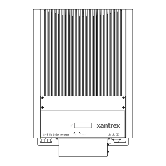
Introduction Heat sink LED indicator lights DC quick-connects AC connection Communication ports cover Mounting slots (five) Figure 1-2 Main Features of the GT Inverter (GT2.5-DE/2.8-SP Models Shown) 1–4 975-0253-01-01 www.xantrex.com.ua... -
Page 23: Installation
The topics in this chapter are organized as follows: • “Installation Options” on page 2–2 • “Planning the Installation” on page 2–2 • “Preparing for the Installation” on page 2–8 • “Mounting the Inverter” on page 2–9. www.xantrex.com.ua... -
Page 24: Installation Options
“Inverter Location” on page 2–4 • “PV Array Requirements” on page 2–5 • “Grounding Requirements” on page 2–7 • “Routing the Wires” on page 2–8. Ensure that you have obtained all permits required by local authorities or utilities before commencing installation. 2–2 975-0253-01-01 www.xantrex.com.ua... -
Page 25: Figure 2-1 Installation Options Overview
Utility Grid Utility Meter Main Utility Harvested Service Panel Grid Tie Grid Tie solar energy Solar Solar Inverter Inverter PV Array #1 GT Inverter #1 GT Inverter #2 DC converted to AC Figure 2-1 Installation Options Overview 975-0253-01-01 2–3 www.xantrex.com.ua... -
Page 26: Inverter Location
Maximum distances will depend on wire gauges used and PV array output voltages. To minimize system failures due to AC voltage faults, Xantrex recommends sizing the AC and DC wiring to have a maximum 1 to 1.5% voltage drop. •... -
Page 27: Pv Array Requirements
All electrical terminations should be fully tightened, secured, and strain recommendations relieved as appropriate. • All mounting equipment should be installed according to the manufacturer’s specifications. • All wires, conduit, exposed conductors and electrical boxes should be secured and supported according to code requirements. 975-0253-01-01 2–5 www.xantrex.com.ua... -
Page 28: Table 2-1 Mppt Operational Window
The solar array should be sized such that its maximum voltage output does not current limits exceed the limits of the MPPT operational window (195/240 to 550 Vdc). See “Guidelines for Matching PV Array Size to Xantrex Grid Tie Solar Inverter Input”. The array voltage should never exceed 600 V (open circuit voltage) under any thermal condition. -
Page 29: Grounding Requirements
Once you know the specifications of your panels, all these factors will help determine the maximum and minimum number of panels that can be used. Visit the Support page at www.xantrex.com to use an online PV array sizing tool. Grounding Requirements... -
Page 30: Routing The Wires
Obtain all permits necessary to complete the installation. Consult your local and national electrical codes for more information. Important: In this manual “wiring” and “wires” are used in reference to both AC and DC wiring/cabling and wires/cables. 2–8 975-0253-01-01 www.xantrex.com.ua... -
Page 31: Wiring
2. Making the DC connections from the PV array to the GT Inverter (“Connecting the DC Wiring” on page 3–2) 3. Making the AC connections from the GT Inverter to the main utility service panel (“Connecting the AC Wiring” on page 3–7) Figure 2-3 summarizes these steps. 975-0253-01-01 2–9 www.xantrex.com.ua... -
Page 32: Tools And Materials Needed
Protective Earth Main Utility Grid Tie Solar Inverter Service Panel Xantrex GT Inverter Figure 2-3 Installation Overview This chapter describes the first step: mounting the inverter and installing accessories. Mounting steps Instructions for mounting the GT Inverter are described in the following sections: •... -
Page 33: Dimensions
Installing the Mounting Bracket The mounting bracket for the GT Inverter allows the unit to be easily mounted and removed for servicing. It has one hook that matches a corresponding hook on the back side of the inverter. 975-0253-01-01 2–11 www.xantrex.com.ua... -
Page 34: Figure 2-5 Mounting Bracket And Gt Inverter
Units can be mounted side by side with no clearance between them, but 15 cm of clearance around the outermost two units is recommended. In hot climates, some clearance between units may be needed to prevent thermal derating. 2–12 975-0253-01-01 www.xantrex.com.ua... - Page 35 GT Inverter. It is recommended to use 6 mm diameter fasteners. However, because mounting surfaces can vary, installers must select appropriate hardware for each installation. Important: Local codes may impose additional mounting requirements in earthquake or other high-risk areas. 975-0253-01-01 2–13 www.xantrex.com.ua...
-
Page 36: Figure 2-6 Examples Of Mounting On A Pole Or Rails
34 cm Mounting bracket At least 2 bolts to secure bracket to 46 cm poles/rails. 130 cm For securing the bottom of the inverter 100 cm Ground/Floor Figure 2-6 Examples of Mounting on a Pole or Rails 2–14 975-0253-01-01 www.xantrex.com.ua... -
Page 37: Figure 2-7 Installing The Mounting Bracket Using Plywood Support
5. Remove the bracket and drill the holes using an appropriately sized drill bit. Drill appropriately sized holes for screws or anchors. 6. Secure the bracket to the supporting surface using at least two screws and washers. 975-0253-01-01 2–15 www.xantrex.com.ua... -
Page 38: Mounting The Inverter On The Bracket
Slide the mounting hooks on the inverter Ensure the inverter is over the hooks on the mounting bracket. seated properly on the mounting bracket Flange with mounting slots 130 cm 100 cm Figure 2-8 Proper Placement of the Inverter on the Mounting Bracket 2–16 975-0253-01-01 www.xantrex.com.ua... -
Page 39: Wiring The Inverter
The topics in this chapter are organized as follows: • “Connecting the DC Wiring” on page 3–2 • “Connecting the AC Wiring” on page 3–7 • “Connecting Multiple Inverters” on page 3–6 • “Communications Wiring for Multiple Inverters” on page 3–10 www.xantrex.com.ua... -
Page 40: Connecting The Dc Wiring
The GT Inverter is equipped with four PV quick connects (two positive, two negative) for connecting up to two PV strings. The GT5.0-SP model has six PV quick connects for connecting up to three PV strings. GT2.5-DE, GT3.8-DE, GT2.8-SP, GT3.8-SP PV positive (+) AC quick connect PV negative (–) -
Page 41: Equipment Needed
KLKD 001., KLKD 01.5, KLKD 002., KLKD 02.5, KLKD 003., KLKD 03.5, KLKD 004., KLKD 005., KLKD 006., KLKD 007., KLKD 008., KLKD 009., KLKD 010., KLKD 012., KLKD 015. Ferraz Shawmut DCT5-2, DCT8-2, DCT10-2, DCT12-2, DCT15-2 Bussmann FWC-6A10F, FWC-8A10F, FWC-10A10F, FWC-12A10F 975-0253-01-01 3–3 www.xantrex.com.ua... -
Page 42: Connecting The Pv Array
Three PV Strings)” on page 3–3. See Figure 3-2. To wire the PV array to the GT Inverter: 1. If necessary, install DC conduit from the PV string(s) to the GT Inverter. 2. Terminate the wires coming from the PV string(s) with appropriate Multi-Contact connectors. 3–4 975-0253-01-01 www.xantrex.com.ua... -
Page 43: Figure 3-3 Dc Connections For A Two-String Pv Array
– PV String #2 – PV String #1 Xantrex GT Inverter Figure 3-3 DC Connections for a Two-String PV Array Depending upon installation and local codes, fusing and/or a combiner Important: box may be required. The installer must provide this equipment. -
Page 44: Connecting Multiple Inverters
PV1 negative (–) to inverter 2. As shown in Figure 3-4, this configuration can cause short circuit failures in the inverters and may also generate hazardous voltages within the system. – – PV Array #1 PV Array #2 GT Inverter #2 GT Inverter #1 Figure 3-4 Improper Multiple Inverter Connections 3–6 975-0253-01-01 www.xantrex.com.ua... -
Page 45: Connecting The Ac Wiring
The GT Inverter must be connected to the utility with three wires—two lines (one Active phase and one neutral phase) and one protective earth (ground). Making AC Connections for GT2.5-DE, GT3.8-DE, GT2.8-SP, GT3.8-SP Models GT Inverter models GT2.5-DE, GT3.8-DE, GT2.8-SP, GT3.8-SP are equipped with a quick connect for making AC connections. -
Page 46: Figure 3-5 Ac Connector (Female)
1. Line up the notch on the female AC cable connector with the connector on the GT Inverter. 2. Insert the AC cable connector into the connector on the GT Inverter. 3. Secure the connector by turning the outer ring. 3–8 975-0253-01-01 www.xantrex.com.ua... -
Page 47: Making Ac Connections For Gt5.0-Sp Model
1. Strip 10 mm of insulation on the three wires from the utility panel. 2. Remove the inverter front panel. It is held in place by four screws—two along the bottom and two on the front. The AC wiring compartment is behind the front panel. 975-0253-01-01 3–9 www.xantrex.com.ua... -
Page 48: Communications Wiring For Multiple Inverters
Communications wiring between multiple GT Inverters allows information about each inverter and its associated PV array to be communicated between all of the inverters in the system. Information about the entire system can be displayed on any inverter LCD in the system. 3–10 975-0253-01-01 www.xantrex.com.ua... -
Page 49: Xanbus Network Technology
PV array. Xanbus Network Technology GT Inverters are Xanbus-enabled devices. They use Xanbus Network Technology™ (a communications protocol developed by Xantrex) to communicate with other GT Inverters. Each GT Inverter is connected by an CAT5 cable, as shown in Figure 3-8. -
Page 50: Figure 3-9 Network Terminator
Xanbus baud rate is set to 125 kbps by default. If you want to switch to 250 Important: kbps, make sure to follow the recommended procedure supplied by Xantrex. See the Application Note, “Xantrex Grid Tie Solar Inverter Baud Rate Change Procedure”... -
Page 51: Figure 3-10 Location Of Xanbus Rj45 Ports
Table 3-3 provides a partial list of network components and part numbers. Pre-made cables are available in lengths from 0.9 to 22.9 metres. Call your dealer or visit www.xantrex.com for information on purchasing network components. 975-0253-01-01 3–13... -
Page 52: Guidelines For Routing The Network Cables
3. Pass the cable through the cable clamp on the communication ports cover of Inverter #1. 4. Pass the cable between Inverter #1 and Inverter #2, securing the cable appropriately. 5. Pass the cable through the cable clamp on the communication ports cover of Inverter #2. 3–14 975-0253-01-01 www.xantrex.com.ua... -
Page 53: Verifying The Xanbus Network
Diagnostic Tool for NMEA 2000 compatible networks. To determine if the network is healthy, check to see if any bus errors are present on the network. The presence of bus errors, specifically more than one bus error per second, indicates that the network is not operating optimally. 975-0253-01-01 3–15 www.xantrex.com.ua... -
Page 54: Communications Wiring For Monitoring A Single Inverter
Communications Wiring for Monitoring a Single Inverter You can view GT Inverter operational data on a personal computer using the Xantrex GT Solar Inverter Viewer (“GT-View”), which you can download free of charge at www.xantrex.com. To use GT-View, you must connect your computer’s serial port to the GT Inverter RS-232 port (see Figure 3-10). - Page 55 DB9 cable connections (one per inverter) to your computer. GT-View displays operational data such as power output in AC watts, lifetime energy produced, and inverter temperature. Data is updated every two seconds (default setting). 975-0253-01-01 3–17 www.xantrex.com.ua...
- Page 56 Wiring the Inverter 3–18 975-0253-01-01 www.xantrex.com.ua...
-
Page 57: Starting The Inverter
Starting the Inverter Chapter 4, “Starting the Inverter”, contains information on starting up the Xantrex Grid Tie Solar Inverter and performing a functional test. The topics in this chapter are organized as follows: • “Commissioning Procedure” on page 4–2 • “Disconnect Test” on page 4–3. -
Page 58: Commissioning Procedure
2. Ensure the correct multi-contact PV connectors are firmly plugged into the GT Inverter as described in “Connecting the DC Wiring” on page 3–2. 3. (GT2.5-DE, GT3.8-DE, GT2.8-SP, GT3.8-SP only) Ensure the AC quick connect is firmly inserted into the GT Inverter and that the coupling ring is tight. -
Page 59: Disconnect Test
Solar Inverter both on initial operation and periodically through its life as required by the utilities. This test ensures that the Xantrex Grid Tie Solar Inverter does not “island” by sending electricity to the utility grid when the local utility has shut off the grid for repairs, or when the utility wiring is damaged. - Page 60 4–4 www.xantrex.com.ua...
-
Page 61: Monitoring The Inverter
LCD screens and the LED indicators. The topics in this chapter are organized as follows: • “Monitoring the Front Panel Display” on page 5–2 • “Front Panel Display Screens and What They Mean” on page 5–3 • “Status Indicator Lights” on page 5–11. www.xantrex.com.ua... -
Page 62: Monitoring The Front Panel Display
The front panel display shows different message screens during different modes of operation (Startup, Normal, Offline, and Fault). All single units display a basic set of message screens; multiple unit systems display additional screens in Normal Operation and Offline modes. 5–2 975-0253-01-01 www.xantrex.com.ua... -
Page 63: Startup Mode
Startup Mode During startup, the GT Inverter displays several message screens on its front panel LCD. GT2.5-DE, For GT2.5-DE, GT3.8-DE, GT2.8-SP, and GT3.8-SP models, the startup screens GT3.8-DE, appear in the order shown in Table 5-1. GT2.8-SP, and Table 5-1 Startup Screens on GT Inverter Front Panel Display GT3.8-SP... - Page 64 * The voltage and frequency thresholds, clear times and reconnect delay in Table 5-1 can be adjusted for multi-unit installations producing 30 kW or more (with the permission of the local utility) using GTConfigLite software. 5–4 975-0253-01-01 www.xantrex.com.ua...
-
Page 65: Normal Operation Mode
Each screen is displayed for a maximum of 30 seconds. If you do not tap again during that time period, then the LCD backlight turns off and the display reverts to the default system message screen. 975-0253-01-01 5–5 www.xantrex.com.ua... -
Page 66: Table 5-4 Normal Operation Screens For All Gt Inverters
Each message is displayed for up to 30 seconds. If you do not tap again within that time period, then the LCD backlight turns off and the display reverts to the default normal operation screen (Table 5-3). 5–6 975-0253-01-01 www.xantrex.com.ua... -
Page 67: Offline Mode
Total time that the system was online today, in hh:mm:ss hours (hh), minutes (mm) and seconds (ss). * In a multiple unit system with network cables installed, the system values displayed are for the entire system. Time online is for the local inverter. 975-0253-01-01 5–7 www.xantrex.com.ua... -
Page 68: Fault Mode
This message applies to the GT5.0-SP only. The AC output current is over the allowable limit, which is 0.5 A less than the maximum output fault current. See“Electrical Specifications” on page A–2. The message clears after 15 seconds if the output current falls below the limit. 5–8 975-0253-01-01 www.xantrex.com.ua... - Page 69 “Reconnecting in sss seconds” and “Inverter Offline” special screens (see Table 5-11) flashing alternately until the countdown is complete. ‡ Applicable to North American models only. European models do not have a ground fault protection fuse installed. 975-0253-01-01 5–9 www.xantrex.com.ua...
-
Page 70: Special Screens
Grid. This is a protection timer that runs at startup and after any Grid fault. Inverter GT Inverter switching (or has switched) from Normal Offline Operation to Offline mode. This screen may flash alternately with a Fault message screen. 5–10 975-0253-01-01 www.xantrex.com.ua... -
Page 71: Custom Screens
Turns off when a fault state is detected. Ground fault condition detected. Check for any fault messages on the display (see Table 5-9), and refer also to Table 6-1, “Troubleshooting the GT Inverter” on page 6–4 to resolve the fault condition. 975-0253-01-01 5–11 www.xantrex.com.ua... -
Page 72: Figure 5-2 Location Of Status Indicator Lights
Monitoring the Inverter Green LED Red LED Figure 5-2 Location of Status Indicator Lights 5–12 975-0253-01-01 www.xantrex.com.ua... -
Page 73: Maintenance And Troubleshooting
Attempting to service the unit yourself could result in electrical shock or fire. Chapter 6, “Maintenance and Troubleshooting”, contains information about how to provide general maintenance for the Xantrex Grid Tie Solar Inverter. It also provides information about troubleshooting the unit. -
Page 74: Factors Affecting Gt Inverter Performance
However, the output loss is not proportionate to shading. The GT Inverter is designed to maximize its energy production in all of the above situations using its MPPT algorithm. 6–2 975-0253-01-01 www.xantrex.com.ua... -
Page 75: Other Factors
• Wire losses For additional information and technical notes concerning PV array performance, please visit our Web site at www.xantrex.com. Performing General Maintenance Follow these simple routines to ensure many years of service and optimal performance of your solar energy system. -
Page 76: Identifying Error/Fault Conditions And Solutions
Check DC connections at the and DC Voltage Fault with sufficient inverter’s positive and negative DC sunlight. terminals. Check for incorrectly wired PV arrays. Ensure a voltage within the operating voltage range is present at the inverter’s terminals. 6–4 975-0253-01-01 www.xantrex.com.ua... - Page 77 Make sure to follow the daisy-chained network. inverter's baud rate screen shows Tx recommended procedure supplied by and/or Rx error (see Table 5-4 on Xantrex. See the Application Note, page 5–6). Xantrex Grid Tie Solar Inverter Baud Rate Change Procedure (976-0216-01-01 available on www.xantrex.com).
- Page 78 Maintenance and Troubleshooting 6–6 975-0253-01-01 www.xantrex.com.ua...
-
Page 79: A Specifications
Specifications Appendix A, “Specifications”, contains information about the electrical and environmental specifications of the Xantrex Grid Tie Solar Inverter. The topics in this appendix are organized as follows: • “Electrical Specifications” on page A–2 • “Environmental Specifications” on page A–5 •... -
Page 80: Electrical Specifications
Specifications Electrical Specifications Input GT2.5-DE GT2.8-SP GT3.8-DE/SP GT5.0-SP Input voltage, Maximum Power Point range 195 to 550 Vdc 240–550 Vdc Absolute maximum array open circuit voltage 600 Vdc* Maximum input current 14.1 Adc 15.7 Adc 21.3 Adc 24 Adc Maximum array short circuit current... -
Page 81: Adjustable Disconnect Settings (Sp Models Only
GT inverter to operate over a wider grid voltage range. The utility disconnect settings are password protected and should only be changed by qualified service personnel, using the Xantrex GTConfigLite software tool. For more information about installing and using GTConfigLite, see the GTConfigLite User’s Guide, available with the software. -
Page 82: Output Power Versus Ambient Temperature
Once the heat sink on the inverter reaches a temperature limit, the GT Inverter reduces its energy output to ensure maximum component ratings are not exceeded. The following shows the maximum continuous output power derating to be expected at higher ambient temperatures. GT2.5-DE, GT3.8-DE, GT2.8-SP, GT3.8-SP Power Derating Curve 4000 GT3.8 GT3.8 GT3.8... -
Page 83: Efficiency
Environmental Specifications GT5.0-SP Power Derating curve 5000 4500 4000 3500 3000 2500 2000 1500 1000 Figure A-2 Output Power vs. Ambient Temperature (GT5.0-SP) Efficiency GT2.5-DE GT3.8-DE GT2.8-SP GT3.8-SP GT5.0-SP Maximum peak 95.3% 95.3% efficiency Euro efficiency 94.5% 94.5% 95.2% Nighttime tare loss... -
Page 84: Mechanical Specifications
Voltage +/- (1% of rating + 1% of reading) Current +/- (1% of rating + 1% of reading) System Lifetime energy +/- 5% Mechanical Specifications GT2.5-DE GT3.8-DE GT2.8-SP GT3.8-SP GT5.0-SP Outdoor enclosure IP54, Rainproof Inverter dimensions (H × W × D) 597 ×... -
Page 85: Warranty And Return Information
Xantrex will, at its option, use new and/or reconditioned parts in performing warranty repair and building replacement products. Xantrex reserves the right to use parts or products of original or improved design in the repair or replacement. If Xantrex repairs or replaces a product, its warranty continues for the remaining portion of the original Warranty Period or 90 days from the date of the return shipment to the customer, whichever is greater. - Page 86 Claims are limited to repair and replacement, or if in Xantrex's discretion that is not possible, reimbursement up to the purchase price paid for the product. Xantrex will be liable to you only for direct damages suffered by you and only up to a maximum amount equal to the purchase price of the product.
-
Page 87: Return Material Authorization Policy
Return Material Authorization Policy For those products that are not being repaired in the field and are being returned to Xantrex, before returning a product directly to Xantrex you must obtain a Return Material Authorization (RMA) number and the correct factory “Ship To”... -
Page 88: Information About Your System
Warranty and Return Information About Your System As soon as you open your Xantrex Grid Tie Solar Inverter package, record the following information and be sure to keep your proof of purchase. ❐ Serial Number _________________________________ ❐ Product Number _________________________________ ❐... - Page 89 3–3 fuses 2–14 on poles or rails mounting the inverter 2–12 clearance requirements 6–3 2–15 general maintenance on wallboard, siding or concrete 2–4, 2–12 2–4 ground clearance required for installation orientation 1–viii 2–10 ground fault detection overview www.xantrex.com.ua...
- Page 90 5–6 messages in normal operation temperature 5–8 messages in offline mode 6–2 affecting PV array performance 2–4 range for locating Xantrex GT Inverter A–4 thermal derating chart 6–4 operation troubleshooting the GT Inverter 6–2 factors affecting performance 5–3 messages at startup 4–2...
- Page 91 www.xantrex.com.ua...
- Page 92 Xantrex Technology Inc. +34 902 10 18 13 Telephone +34 93 305 50 26 Fax GTsupport.Europe@xantrex.com www.xantrex.com 975-0253-01-01 Printed in China www.xantrex.com.ua...
Need help?
Do you have a question about the GT2.5-DE and is the answer not in the manual?
Questions and answers