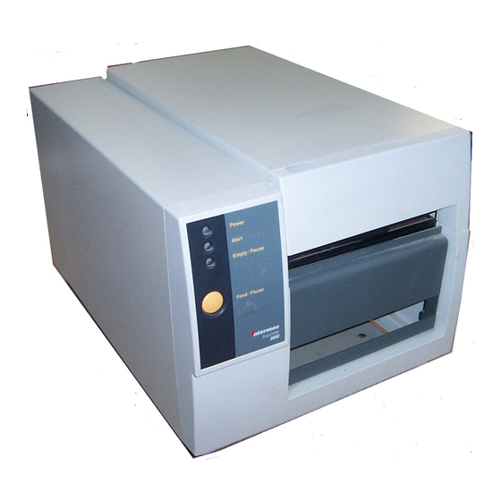
Intermec 3600 Maintenance Manual
Bar code label printer
Hide thumbs
Also See for 3600:
- User manual (8 pages) ,
- Instruction sheet (2 pages) ,
- Developer's manual (116 pages)
Table of Contents
Advertisement
Quick Links
Advertisement
Table of Contents
Troubleshooting

Subscribe to Our Youtube Channel
Related Manuals for Intermec 3600


Summary of Contents for Intermec 3600
- Page 1 Maintenance Manual 3600 Bar Code Label Printer P/N 062905-001...
- Page 2 The software contained in the 3600 printer and the accompanying materials are copyrighted. Unathorized copying of the software, including software that has been modified, merged, or included with other software, or the written materials is expressly forbidden without the prior written consent of Intermec.
- Page 3 hc nug Contributors Technical Writer: Robert Shaw Editor: Craig Thompson Technical Illustrator: George Wilson Technical Reviewers: Cathy Aragon Pixie Austin Daniel Clark John Cramer Allen Crowe Stephen Eckert Pat Helton Laura McCluer Ed Millet Art Millican Matt Roberts Joe Wade...
- Page 4 c 3 9 c 3 9 frank...
-
Page 5: Table Of Contents
Safety Summary xi Warnings and Cautions xii Purpose of This Manual xii Additional Information xv General Information Overview of the 3600 Printer 1-3 3600 Features 1-4 3600 Printer Specifications 1-4 Dimensions (no options installed) 1-4 Electrical Requirements 1-4 Printing Methods 1-4... - Page 6 3600 Printer Maintenance Manual Principal Functional Parts 1-9 Basic Printer Setup and Operation 1-11 Front Panel Operation 1-11 Checking the Printer Configuration 1-12 Connecting the Printer to a Computer 1-13 Printing 1-14 Preventive Maintenance Preventive Maintenance Actions and Intervals 2-3...
- Page 7 Adjusting the Printer 3-13 Adjusting the Print Bias for Print Quality 3-14 Adjusting the Print Intensity 3-15 Adjusting the Printhead Adjustment Lever for Print Quality 3-16 Adjusting the Label Mark Sensor 3-17 Adjusting the Label Gap Sensor 3-19 Adjusting the Label Taken Sensor 3-20...
- Page 8 3600 Printer Maintenance Manual Remove and Replace Procedures Replacing Printer Components 5-3 Replacing the Lithium Battery 5-4 Replacing the Printhead 5-5 Replacing the Bezel PCB 5-6 Replacing the Main PCB 5-8 Replacing the Kanji/Katakana Option PCB 5-9 Replacing the Label Mark Sensor 5-10...
- Page 9 Appendix Functional Description of the 3600 Mechanics A-3 Functional Description of the 3600 Electronics A-4 Power Supply A-4 +5V A-4 +40V A-4 +24V A-4 Power Fail Detection A-5 Battery A-5 Battery Life Calculations A-5 Reset A-5 Motor Driver A-6 Processor A-7...
-
Page 11: Before You Begin
hc nug c 3 9 frank Before You Begin Before You Begin This section describes the purpose and arrangement of this manual to you. It is intended to bring to your attention, important general safety concerns, specific warnings and cautions, and sources of additional information. Safety Summary Your safety is extremely important. -
Page 12: Warnings And Cautions
Purpose of This Manual The purpose of this maintenance manual is to provide the information you need to clean, adjust, and repair the Intermec 3600 Bar Code Label Printer. Who Should Read This Manual? This manual is written for experienced electronic technicians trained by Intermec, who will service and, if necessary, repair the 3600 printer. - Page 13 3 9 frank How This Manual Is Organized You will find the following information in the referenced section: For information about: A basic description of the 3600 Scheduled cleanings and checks Making sure the printer is operating correctly and providing quality results...
-
Page 14: Terms And Conventions
3600 Printer Maintenance Manual Terms and Conventions The following terms and conventions occur throughout this manual. A complete glossary of terms is provided in the 3600 Bar Code Label Printer User’s Manual. Terms “Backing” (or liner) refers to the silicon release portion of the media that carries the label. -
Page 15: Additional Information
Additional Information The following documents may be of interest or help to you in servicing the 3600 printer. 3600 Bar Code Label Printer User’s Manual (P/N 062732) Label Debut User’s Manual (P/N 062982) Data Communications Reference Manual (P/N 044737) The Bar Code Book by Roger C. Palmer... -
Page 17: General Information
c 3 9 frank c 3 9 General Information... - Page 18 c 3 9 frank c 3 9...
-
Page 19: Overview Of The 3600 Printer
3-inch (7.62 cm) to 6.6-inch (16.8 cm) wide continuous feed label stock. The 3600 prints directly to thermal label media or can print on regular label media with the use of a thermal transfer ribbon (TTR). -
Page 20: 3600 Features
3600 Printer Maintenance Manual c 3 9 frank c 3 9 3600 Features The 3600 printer’s features are summarized in the following list: Print speed from 2 to 5 ips Programmable, nonvolatile printer configuration Bitmap font capabilities Outline/vector font support... -
Page 21: Printing Speed
Printing Speed Maximum 5 ips (50.8 mm per second) Minimum 2 ips (127 mm per second) The print speed can be changed in 1 ips increments only: 2, 3, 4, or 5. Printhead Specifications Element size 0.00492 inch square (0.13 mm) Width 6.6 inches maximum print (168 mm) Resolution... -
Page 22: Communications
3600 Printer Maintenance Manual c 3 9 frank c 3 9 Communications Asynchronous RS-232C, RS-422, RS-485 interfaces Serial ASCII code Hardware (Ready/Busy) flow control XON/XOFF protocol Intermec Standard Block protocol Polling Mode D protocol Multi-Drop protocol Baud Rates: 1200, 2400, 4800, 9600, 19200... -
Page 23: Factory Default Settings
Print Speed Label Stock Type Intercharacter Delay 3600 Printer Options The 3600 you are servicing can be equipped with one or more of the following options: Memory Expansion Storage memory for formats, pages, graphics, and fonts can be increased to 512K of battery backed static RAM. -
Page 24: Coax Interface
Connection can be made to an IBM 3174/76/99 system controller/multiplexer. Parallel Interface This option lets the user connect the 3600 to a PC through any Centronics™ parallel interface in addition to the standard serial interface. Network Connectivity Using the Parallel Interface option and an Ethernet or other network adapter, the 3600 can be connected to a network. -
Page 25: Principal Functional Parts
Principal Functional Parts The following illustrations identify the common name and location of the major functional elements of the 3600 printer. Front Panel c 3 9 frank I n t e r m e Media access door Darkness adjust control... - Page 26 3600 Printer Maintenance Manual c 3 9 frank c 3 9 TTR takeup hub TTR roller Tear bar Platen roller Media access door 1-10 Media post TTR supply hub I n t e I n t e r m e...
-
Page 27: Basic Printer Setup And Operation
Basic Printer Setup and Operation Detailed operating instructions for the 3600 printer are contained in the user’s manual. This section summarizes the following basic setup and operating information for you as a quick reference: Front panel operations Checking printer configuration... -
Page 28: Media Or System Faults
Checking the Printer Configuration The factory default settings for the 3600 printer are listed with the 3600 specifications in this chapter. These parameters are set using a combination of DIP switch settings and downloadable printer commands, which are described in the user’s manual. -
Page 29: Dip Switch Settings
Connecting the Printer to a Computer To operate as intended, the 3600 must be interfaced with a computer (desktop or laptop PC, local area network, AS400 or similar mainframe) with its serial port configured for the communications protocol appropriate to the computer interface. -
Page 30: Printing
Using Third-Party Software Your customer may be using third-party software to create label formats and convert graphics into a UDC format that the 3600 printer can interpret. You can use the same software to set the printer parameters. 1-14... -
Page 31: Using The Printer Command Set
You can also create labels by downloading formats (designs) and data created with the printer command set. The commands in the printer command set can perform any function or activate any feature of the 3600 printer. You can use the following methods to download commands:... - Page 32 c 3 9 frank c 3 9...
-
Page 33: Preventive Maintenance
Preventive Maintenance... -
Page 35: Preventive Maintenance Actions And Intervals
Printer Component Maintenance Action and Interval Printer Inspect the printer (and the rest of the data collection system) at every service visit. Your inspection should include the types of items listed in the following section. Printhead Inspect after every roll of media. -
Page 36: Inspecting The Printer
3600 Printer Maintenance Manual Inspecting the Printer You should routinely inspect the printer and the rest of the data collection system. Your inspection needs to address the following and similar concerns: Make sure the printer is properly grounded. Make sure the printer’s AC power source is within tolerance. -
Page 37: Removing The Media Cover
1. Place your fingers in the space at the lower center edge of the media cover and pull the bottom of the cover away from the base of the printer. 2. Grasp the front of the media cover and lift the front of the cover upward. -
Page 38: Cleaning The Printhead
3600 Printer Maintenance Manual Cleaning the Printhead Since the printhead must maintain close contact with the media to provide good print quality, cleaning media debris from the printhead is very important. Clean the printhead after every roll (or 6,000 inches) of media or whenever necessary. - Page 39 3. Remove the media from the paper path and the ribbon (if installed) from the TTR supply and takeup hubs. 4. Use a cotton swab moistened with alcohol to remove any dirt, adhesive, or debris from the print surface on the bottom of the printhead. I n t e r m e Thermal...
-
Page 40: Cleaning The Rollers And Tear Bar
3600 Printer Maintenance Manual Cleaning the Rollers and Tear Bar Cleaning the platen roller and the tear bar preserves print quality by ensuring close contact between the media and the printhead. The TTR roller, liner roller, and media roller are cleaned in the same fashion to minimize general debris and to maximize their efficiency. -
Page 41: Cleaning The Media Guides And Media Path
Media debris may accumulate around the printer mechanism and along the media path during normal operation of the printer. Clean debris away using a soft bristle brush or vacuum cleaner. Remove all traces of dust, paper, and adhesive. - Page 42 3600 Printer Maintenance Manual 5. Use a lint-free cloth moistened with isopropyl alcohol to clean the upper media guide. Be sure to remove all traces of debris. 6. Reload the media (and ribbon if used). 7. If you are finished cleaning, install the media cover.
-
Page 43: Cleaning The Label And Ribbon Sensors
Cleaning the Label and Ribbon Sensors There are three label sensors and a ribbon sensor on the 3600 printer that require cleaning: the label taken sensor, the label mark sensor, the label gap sensor, and the ribbon motion sensor. To clean the sensors 1. -
Page 44: Cleaning The Printer Covers
12. If you are finished cleaning, install the media cover. Cleaning the Printer Covers Clean the 3600 printer covers with a general purpose cleaner (soapy water/mild detergent). Do not use abrasive cleansers or solvents. Be sure to clean the transparent panel on the media cover so that you can see the media supply inside the printer when the cover is closed. -
Page 45: Testing And Adjusting
Testing and Adjusting... -
Page 47: Testing The Printer
The quality and efficiency of producing labels reveals if a printer is operating correctly. In addition to analyzing labels to evaluate printer performance, the 3600 printer Test and Service mode allows you to conduct printer tests that include printing test labels (illustrated in this section) with a fixed look so you can compare them to an expected standard. -
Page 48: Running Test And Service Mode At The Printer
3 9 Running Test and Service Mode at the Printer Note: When the printer is placed in Test and Service mode, it prints out a hardware configuration label, regardless of its initial DIP switch settings, and remains in Test and Service mode until the power is switched off and the DIP switches are reset. - Page 49 Test and Service Switch Settings O = OFF 1 = ON TESTS Test Prints Configurations Test Labels Page Format Font Data Line Print Cloning Receiver Sender Selective Transfer Receiver Send Pages Send Format Send UDC Send Font Send Configuration Send Tables Send All Memory Reset A: OFF = Batch of 1.
- Page 50 3600 Printer Maintenance Manual c 3 9 frank c 3 9 Test and Service Configuration Settings O = OFF 1 = ON Label Rest Point 86XX Emulation X Forms Adjust Y Forms Adjust N: Number. Least significant bit first. Dot Increment Switch Settings...
-
Page 51: Printing Test Labels
Firmware checksum, program, and version number. Vertical lines for evaluating printhead alignment. To achieve the highest quality label, print the hardware configuration label at a speed of 3 ips (inches per second). 3600 Hardware Configuration Memory Installed Storage RAM : 128 kilobytes... - Page 52 This label contains bar codes and human readable fields that you can use to determine whether the printer you are testing is attaining the best print quality possible. If you notice problems with the print quality, check and perform the adjustment and alignment procedures provided in this chapter to achieve optimum printer performance.
- Page 53 This label, which can be a test of a single format or can provide a two-label sample of all the formats, has bar codes and human-readable fields that you can use to determine whether the printer you are testing is attaining the best print quality possible using a particular format.
- Page 54 (bitmap graphic) from a host. The data can be yours or the customer’s, but you should include a test of the customer’s labels to determine whether the printer you are testing is attaining the best print quality possible with the customer’s data.
-
Page 55: Running Test And Service Mode From A Host Computer
Running Test and Service Mode From a Host Computer When conducting Test and Service mode functions from a computer, hardware diagnostic information is uploaded to the host from the printer. The following table describes the commands you would issue from a host terminal to run the Test and Service mode. -
Page 56: Testing Printer And Host Communications
Testing Printer and Host Communications This is a simple test of host-to-printer communications. If this test fails, there may be a problem with the printer serial port receiver circuitry or the setup. To test host-to-printer communications 1. Switch the printer power off. Return the DIP switch settings to the standard configuration if they have been changed. -
Page 57: Adjusting The Printer
COM1 of your PC. Note: If you are using a different platform to communicate with your printer, refer to your host computer user’s manual and the 3600 Bar Code Printer User’s Manual for more detailed information about downloading commands. -
Page 58: Adjusting The Print Bias For Print Quality
3600 Printer Maintenance Manual c 3 9 frank c 3 9 Adjusting the Print Bias for Print Quality Adjust the bias with a straight-slot screwdriver if the printhead is not making even contact with the media. Using different width media, especially narrow media, can result in uneven contact or a spot where there is no media between the printhead and the platen roller. -
Page 59: Adjusting The Print Intensity
<SI>d to fine-tune the intensity of print on your customer’s labels. The fine adjustments compensate for variations in the media (“lot to lot”), the printhead, or the printer. Set the darkness adjust control with a small straight- slot screwdriver after entering the proper sensitivity number. -
Page 60: Adjusting The Printhead Adjustment Lever For Print Quality
3600 Printer Maintenance Manual c 3 9 frank c 3 9 Adjusting the Printhead Adjustment Lever for Print Quality The printhead adjustment lever is located at the end of the printhead pivot bracket. It allows fine-tuning of the printhead fore/aft position. The printhead adjustment lever provides three stops forward movement of the printhead and three stops backward movement from center position in 0.006-inch increments. -
Page 61: Adjusting The Label Mark Sensor
2. Use your finger to reach underneath the lower guide. Platen roller Locate the label mark sensor behind the platen roller near the inboard edge of the printer. Use your index finger to adjust the label mark sensor. Inboard edge of printer. - Page 62 1. Remove the electronics cover 2. Switch on the printer power. 3. Enable the printer for mark sensing using the <SI>T{2} command. 4. Connect the positive lead of a digital voltmeter to TP18 (MARK) and the negative end to TP14 (GND) on the main PCB.
-
Page 63: Adjusting The Label Gap Sensor
The label gap is the space between labels on the backing material. This reading enables the printer to properly position the start of print point. To perform this procedure, you need the following... -
Page 64: Adjusting The Label Taken Sensor
TP14 (GND) on the main PCB. 3. Switch on the printer power. 4. Feed one label out of the printer so that it rests under the label taken sensor in a correct orientation. 5. Adjust R190 on the main PCB until the voltage at TP19 is 1.2V + 0.2V. -
Page 65: Aligning The Printer
Aligning the Printer The following procedures provide instructions for aligning the rollers, aligning the printhead, and aligning the ribbon supply hub on the 3600 printer. Note: These alignments should be made in the sequence given. Performing them out of order can introduce and not solve printing problems. -
Page 66: Aligning The Rollers
You should perform this procedure every time an outboard plate is removed or replaced. To perform this procedure, you need the following tools: Note: If the printer you are servicing has upper outboard plate Intermec Part No. 062476-002 installed, you need to replace it with a new upper outboard plate Intermec Part No. -
Page 67: Aligning The Printhead
9/64-inch Allen screwdriver To align the printhead 1. Switch off the printer power. Remove the power cord and the media cover. 2. Raise the printhead with the printhead lift lever. Remove media and ribbon. 3. Position the printhead adjustment lever clockwise/left two clicks during the printhead alignment. - Page 68 7. Return the printhead adjustment lever to the neutral/center position. 8. Reload media (and ribbon if used). 9. Install the media cover and the power cord. 10. Switch on printer power and test for proper printhead alignment by printing out the print quality and pitch labels. Place the cutouts...
-
Page 69: Aligning The Ttr Supply Hub
TTR supply hub alignment tool, Intermec Part No. T43149 #2 Phillips screwdriver To align the TTR supply hub 1. Switch off the printer power. 2. Remove the media cover and the electronics cover. 3. Install the TTR supply hub alignment tool as shown. - Page 70 8. When an alignment is achieved that eliminates the ribbon wrinkling, tighten the two screws on the hub adjustment plate. 9. Remove the tool and retest for ribbon wrinkling. 10. After the printer is correctly adjusted, switch off the power and reattach the electronics and media covers. 3-26...
-
Page 71: Troubleshooting
Troubleshooting... -
Page 73: About Troubleshooting And Repair
About Troubleshooting and Repair Use the information in this chapter to identify the cause of a failing printer. It is assumed that a printer is not working and that the troubleshooting actions referenced in the user’s manual were not used, failed to clear the problem, or... -
Page 74: Troubleshooting Checklist
If the printer does not send an error message to the host, try to match the symptom of your failure in the “Printer Operation Problems” or “Print Quality Problems”... -
Page 75: Error Handling
Syntax Errors The 3600 printer responds to syntax errors in the messages it receives from the host by attempting to execute the commands. It does not ignore a command with a syntax error. Instead, the printer produces output, even if it is erroneous, which gives you an indication of what went wrong and what should be done to correct the problem. -
Page 76: Invalid Numeric Character Errors
RAM. Error Codes Most of the problems you may encounter cause the 3600 printer to send an error code to the host. When this happens, find the error code in the following table and try the solution given to attempt to correct the problem. - Page 77 Printer Errors Error Code Problem No error. Invalid bar code check character. Invalid number of bar code characters (Code UPC/EAN). Bar code check character within numeric field marks. Supplemental delimiter within numeric field marks (Code UPC/EAN). Invalid supplemental character count (UPC/EAN).
- Page 78 3600 Printer Maintenance Manual Printer Errors (continued) Error Code Problem Non-immediate command or data received after buffer full. Invalid field delimiters. Invalid escape command. Invalid data shift command. Invalid or undefined format number. Insufficient room in RAM to print format.
-
Page 79: Printer Operation Problems
Printer Operation Problems If a printer is not operating correctly, try locating the problem and implementing the solution from the following table: Symptom Possible Causes No power or loss of AC power cable is damaged or power. disconnected. Printer circuit breaker tripped. -
Page 80: Print Quality Problems
3600 Printer Maintenance Manual Print Quality Problems If labels are not printing properly, try locating the problem and implementing the solution in the following table: Symptom Possible Causes Blotches on labels. Dirty printhead. Dirty media path or rollers. Poor quality label or ribbon stock. - Page 81 Symptom Possible Causes Print quality is poor. Incorrect media sensitivity. The darkness of label print is too light or too dark. Printhead, platen roller, or label path are dirty. Uneven print contrast (density). Incorrect label or ribbon stock is used to print labels. Ribbon wrinkling.
-
Page 82: Communications Problems
Disconnected, damaged, or incorrect I/O cable. Any loss of data can cause printing errors or missing data. The 3600 printer is a serial ASCII device that communicates with the host through an ASCII serial communications port. The two devices communicate through the use of hardware and software protocols (handshaking). -
Page 83: Environmental Problems
One way to discover if the problem is environmental is to see if the problem goes away when the printer is moved to a new location. If it shows up in a printer recently moved from another area, the problem is probably environmental. -
Page 84: Electromagnetic And Radio Frequency Interference
This safety precaution will save people from electric shock in the situation where they touch both the host computer and the printer at the same time while there is a faulty ground in either device. With this wiring, you would normally expect problems with... -
Page 85: Ac Power Problems (Surges, Sags, Spikes, Noise, And Outages)
Troubleshooting AC Power Problems (Surges, Sags, Spikes, Noise, and Outages) Most environmental problems involve the AC power line. In the 3600 printer, 115V supply voltages can range from 90 to 132 VAC. Outside the U.S., 230V supply voltages can range from 180 to 264 VAC. Voltage overages or underages can result from poor utility regulation to in-plant loading of the power service. -
Page 86: Miscellaneous Problems
If the TTR takeup hub fails to roll up ribbon, you may need to replace the upper drive belt and/or the TTR takeup clutch. If a ribbon fault occurs when the printer is in the TTR mode, you may need to replace the TTR encoder sensor. -
Page 87: Remove And Replace Procedures
Remove and Replace Procedures... -
Page 89: Replacing Printer Components
After replacing a component, refer to Chapters 2 and 3 for the procedures to complete the repair by ensuring that you leave the printer performing at its optimum level. Prior to taking any action, review all warnings, cautions, and procedures associated with any component you intend to remove. -
Page 90: Replacing The Lithium Battery
To replace the lithium battery Note: The printer will lose data if the battery fails or is removed. Before removing the battery, upload and save the fonts, formats, pages, graphics, and configuration settings. 1. Switch off the printer power and remove the power cord, the media cover, and the electronics cover. -
Page 91: Replacing The Printhead
ESD grounding strap Medium straight-slot screwdriver To replace the printhead 1. Switch off the printer power and remove the power cord. 2. Remove the media cover. 3. Raise the printhead. Remove media and ribbon if loaded. 4. Release the locks on the printhead cable by pressing in on each side of the cable connector. -
Page 92: Replacing The Bezel Pcb
6. Replace the printhead and cable and tighten the printhead retaining screws. 7. Reload media (and ribbon if used) and lower the printhead. 8. Install the media cover and the power cord and check the printer for proper operation. Replacing the Bezel PCB To replace the bezel PCB, you will need the following parts and tools: Bezel PCB assembly, Intermec Part No. - Page 93 4. Lift the front bezel cover away from the printer and lay it on a flat surface. 5. Use the #2 Phillips screwdriver to remove the two screws that hold the bezel PCB/cover plate assembly to the front bezel cover.
-
Page 94: Replacing The Main Pcb
3600 Printer Maintenance Manual Replacing the Main PCB To replace the main PCB, you will need the following parts and tools: 3600 main PCB assembly, Intermec Part No. 061591S-005 or 06159E-005 ESD grounding strap #2 Phillips screwdriver To replace the main PCB assembly 1. -
Page 95: Replacing The Kanji/Katakana Option Pcb
Replacing the Kanji/Katakana Option PCB To replace a Kanji/Katakana PCB, you will need the following parts and tools: 3600 Kanji/Katakana PCB, bitmap font, Intermec Part No. 060689-001 or 3600 Kanji/Katakana PCB, outline font, Intermec Part No. 060690-001 ESD grounding strap... -
Page 96: Replacing The Label Mark Sensor
3. Raise the printhead. Remove media and ribbon if loaded. 4. Remove the screws securing the lower outboard plate to the printer and pull it away from the printer. Retain the tear bar and tear bar support. Tear bar 5-10... - Page 97 Any slack in the cable should be arranged between the sensor and the cable clip on the extrusion. There should be no slack cable on the electronics side of the printer. Make sure the cable is secure and not contacting any moving parts.
-
Page 98: Replacing The Label Taken Sensor
#1 and #2 Phillips screwdriver To replace the label taken sensor 1. Switch off the printer power and remove the power cord. 2. Remove the media cover, the electronics cover, and the front bezel cover (refer to “Replacing the Bezel PCB” earlier in this chapter). -
Page 99: Replacing The Label Gap Sensor
Small straight-slot screwdriver 12-inch shank #2 Phillips screwdriver To replace the label gap sensor 1. Switch off the printer power and remove the power cord, the media cover and the electronics cover. 2. Raise the printhead. Remove media and ribbon if loaded. - Page 100 3600 Printer Maintenance Manual Label sensor 6. Use a small straight-slot screwdriver to lift up on each of the two molded tabs that secure the label gap sensor. Slide the label gap sensor from its housing and replace it with the new label gap sensor. The label gap sensor should snap into place.
-
Page 101: Replacing The Ttr Drive Roller And Gear/Pulley
#1 and #2 Phillips screwdriver To remove the TTR drive roller and TTR drive gear/pulley 1. Switch off the printer power and remove the power cord. 2. Remove the media cover, the electronics cover, and the front bezel cover (refer to “Replacing the Bezel PCB” earlier in this chapter). - Page 102 E-ring 7. Unhook the printhead spring from the upper outboard plate and remove the screws securing the plate to the printer. Pull the plate away, freeing up the TTR drive roller (and the TTR shaft, printhead pressure cam assembly, and pivot block).
- Page 103 (snaps firmly shut) after the front bezel cover is installed. 9. Reload media (and ribbon if used) and lower the printhead. 10. Install the electronics cover, the media cover, and the power cord, and check the printer for proper operation. Remove and Replace Procedures 5-17...
-
Page 104: Replacing The Ttr Takeup Hub, Clutch/Pulley, And Belt
#1 and #2 Phillips screwdriver To remove the TTR takeup hub, TTR takeup clutch/pulley, and TTR drive belt 1. Switch off the printer power and remove the power cord. 2. Remove the media supply cover, the electronics cover, and the front bezel cover (refer to “Replacing the Bezel PCB”... - Page 105 (snaps firmly shut) after the front bezel cover is installed. 6. Reload media (and ribbon if used) and lower the printhead. 7. Install the electronics cover and the media cover. 8. Install the power cord and check the printer for proper operation. Remove and Replace Procedures 5-19...
-
Page 106: Replacing The Ttr Supply Hub And Adjusting Plate
TTR supply hub shaft as shown on the next page. Retain the washer. Discard the old snap rings. 5. Pull the TTR supply hub away from the printer and remove the TTR supply clutch/encoder assembly. Retain the TTR supply clutch/encoder assembly (this assembly is not a spare part), the nylon washer, and the thick steel washer. - Page 107 Hub” in Chapter 3. 6. Reload media (and ribbon if used) and lower the printhead. 7. Install the electronics cover, the media cover, and the power cord, and check the printer for proper operation. Remove and Replace Procedures supply hub 3600M.056...
-
Page 108: Replacing The Platen Roller And Gear
Snap ring pliers To remove the platen roller and platen roller gear 1. Switch off the printer power and remove the power cord. 2. Remove the media cover, the electronics cover, and the front bezel cover (refer to “Replacing the Bezel PCB” earlier in this chapter). - Page 109 (snaps firmly shut) after the front bezel cover is installed. 6. Reload media (and ribbon if used) and lower the printhead. 7. Install the electronics cover, the media cover, and the power cord, and check the printer for proper operation. Remove and Replace Procedures Platen...
-
Page 110: Replacing The Liner Drive And Takeup Components
Snap ring pliers To replace the liner takeup hub and liner reverse gear 1 1. Switch off the printer power and remove the power cord. 2. Remove the media cover, the electronics cover, and the front bezel cover (refer to “Replacing the Bezel PCB” earlier in this chapter). - Page 111 Liner reverse gear 1 Thin washer Snap ring Liner takeup Liner reverse gear 1 Subplate Liner Motor reverse plate gear 2 Remove and Replace Procedures Thick washer Main deck plate Liner drive roller Liner drive gear/pulley 3600M.058 Liner takeup 5-25...
- Page 112 To replace the liner drive roller 1. If not already done, switch off the printer power and remove the power cord, media cover, electronics cover, and the front bezel cover. Raise the printhead and remove the media and ribbon if loaded.
- Page 113 (snaps firmly shut) after the front bezel cover is installed. 12. Reload media (and ribbon if used) and lower the printhead. 13. Install the electronics cover, the media cover, and the power cord, and check the printer for proper operation. Remove and Replace Procedures 5-27...
- Page 114 3600 Printer Maintenance Manual To replace liner reverse gear 2, the liner takeup clutch/pulley, liner reverse shaft, liner drive gear/pulley, and liner drive belt 1. If not already done, perform Steps 1 through 5 of the preceding liner roller replacement procedure.
- Page 115 (snaps firmly shut) after the front bezel cover is installed. 9. Reload media (and ribbon if used) and lower the printhead. 10. Install the electronics cover, the media cover, and the power cord, and check the printer for proper operation. Remove and Replace Procedures 5-29...
-
Page 116: Replacing The Stepper Motor
#2 Phillips screwdriver To replace the stepper motor 1. Switch off the printer power and remove the power cord, the media cover, and the electronics cover. 2. Unplug the motor cable from the main PCB and remove the motor from the motor plate and motor mount bracket. -
Page 117: Replacing The Ac Plug/Input Filter
Replacing the AC Plug/Input Filter To replace the AC plug and input filter assembly, you will need the following parts and tools: 3600 line AC plug and filter assembly, Intermec Part No. 060246-001 ESD grounding strap #1 and #2 Phillips screwdriver... -
Page 118: Replacing The Power Switch/Circuit Breaker
To replace the power switch and circuit breaker assembly, you will need the following parts and tools: Note: The 220-volt printer uses a 1 amp power switch/circuit breaker and the 115-volt printer uses a 2 amp power switch/circuit breaker. AC power switch/circuit breaker, Intermec Part No. 501273-001 (2A) or AC power switch/circuit breaker, Intermec Part No. -
Page 119: Replacing The Transformer
To replace the transformer, you will need the following parts and tools: Note: The printer uses a different transformer for 220-volt and 115-volt printers. XFMR, 3600, 47-63HZ, 100V/120V, Intermec Part No. 585525-001 or XFMR, 3600, 47-63HZ, 200V/240V, Intermec Part No. 585525-002... - Page 120 3600 Printer Maintenance Manual 3. Remove the two screws holding the transformer to the base plate and slide the transformer toward the front of the printer to free it from the metal tabs, lifting it away from the printer. 4. Install the replacement transformer and push it toward the back of the printer securing it under the tabs in the printer main deck plate.
-
Page 121: Pcb Drawings And Schematics
PCB Drawings and Schematics... - Page 123 This chapter contains the assembly drawings, parts lists, and schematic diagrams for the 3600 main PCB. PL# 061591-003 TITLE: PCB ASSY,MAIN,3600 PL REV: D RUN DATE: Feb 23 15:19:02 -------------------------------------------------------------------------------- ITEM QTY/UM PART NO. -------------------------------------------------------------------------------- 061590-003 2 0.001 RL 046766 584274 "...
- Page 124 3600 Printer Maintenance Manual PL# 061591-003 TITLE: PCB ASSY,MAIN,3600 PL REV: D RUN DATE: Feb 23 15:19:02 -------------------------------------------------------------------------------- ITEM QTY/UM PART NO. -------------------------------------------------------------------------------- " " " " " " " " " " " " " " " " "...
- Page 125 PL# 061591-003 TITLE: PCB ASSY,MAIN,3600 PL REV: D RUN DATE: Feb 23 15:19:02 -------------------------------------------------------------------------------- ITEM QTY/UM PART NO. -------------------------------------------------------------------------------- " " " " " " " " " " " " " " " " " " " " "...
- Page 126 3600 Printer Maintenance Manual PL# 061591-003 TITLE: PCB ASSY,MAIN,3600 PL REV: D RUN DATE: Feb 23 15:19:02 -------------------------------------------------------------------------------- ITEM QTY/UM PART NO. -------------------------------------------------------------------------------- " " " " " " " " " " " " " " " " "...
- Page 127 PL# 061591-003 TITLE: PCB ASSY,MAIN,3600 PL REV: D RUN DATE: Feb 23 15:19:02 -------------------------------------------------------------------------------- ITEM QTY/UM PART NO. -------------------------------------------------------------------------------- 556648 " " " " 556650 " " " " " " " " 556651 556658 " " " " "...
- Page 128 3600 Printer Maintenance Manual PL# 061591-003 TITLE: PCB ASSY,MAIN,3600 PL REV: D RUN DATE: Feb 23 15:19:02 -------------------------------------------------------------------------------- ITEM QTY/UM PART NO. -------------------------------------------------------------------------------- " " 561018-001 561908 563602 " 563605 " " " " " " 563606 " " 563700 "...
- Page 129 PL# 061591-003 TITLE: PCB ASSY,MAIN,3600 PL REV: D RUN DATE: Feb 23 15:19:02 -------------------------------------------------------------------------------- ITEM QTY/UM PART NO. -------------------------------------------------------------------------------- " " " " " " " " " " " " " " " " " " " " "...
- Page 130 3600 Printer Maintenance Manual PL# 061591-003 TITLE: PCB ASSY,MAIN,3600 PL REV: D RUN DATE: Feb 23 15:19:02 -------------------------------------------------------------------------------- ITEM QTY/UM PART NO. -------------------------------------------------------------------------------- " " " " " " " " " " " " " " " " "...
- Page 131 PL# 061591-003 TITLE: PCB ASSY,MAIN,3600 PL REV: D RUN DATE: Feb 23 15:19:02 -------------------------------------------------------------------------------- ITEM QTY/UM PART NO. -------------------------------------------------------------------------------- " " " " " " 564206 " " " 564217 564219 " " 564235 564238 " 564239-002 " " "...
- Page 132 3600 Printer Maintenance Manual PL# 061591-003 TITLE: PCB ASSY,MAIN,3600 PL REV: D RUN DATE: Feb 23 15:19:02 -------------------------------------------------------------------------------- ITEM QTY/UM PART NO. -------------------------------------------------------------------------------- " 578211-001 578245-001 " " 578294-001 578300-001 578301-001 " 90 2.610 580231 580285 580359 " " 580434...
- Page 133 3600M.072...
- Page 134 3600M.073...
- Page 135 3600M.074...
- Page 136 3600M.075...
- Page 137 3600M.076...
-
Page 140: Replacement Parts
Replacement Parts... - Page 142 Replacement Parts The following table is a copy of the 3600 service parts matrix with illustration references added. It lists the 3600 printer parts that can be ordered for replacement by the part number indicated. Each part on the list has an ID number corresponding to a callout on the illustration showing its location.
- Page 143 BRACKET, PRINTHEAD PIVOT BLOCK, PIVOT FEET, RUBBER, ADHESIVE BACKED HEATSINK ASSY, PRINTHEAD SCREW, PHM, 8-32X .375 PRINTHEAD, 6.6 INCH, 5 MIL, 3600 CAP, BIAS SCREW PLATE, LOWER MODULE, OUTBD BUTTON, CAP LIGHT PIPE, DOCK/CHARG PCB ASSY, MAIN (*exchange part no.) CABLE ASSEMBLY, BEZEL CABLE ASSY., LABEL TAKEN SENSOR...
- Page 144 061541-001 96, 131 501394-001 059423-002 Replacement Parts Description XFMR, 3600, 47-63HZ, 100V/120V XFMR, 3600, 47-63HZ, 200V/240V JUMPER AY, .25 TERM. LUGS, 4-IN FILTER ASSY, LINE AC WASHER, LOCK, EXT. STAR, NO. CIRCUIT BREAKER, SWITCH, 2 AMP CIRCUIT BREAKER, SWITCH, 1 AMP WASH.
- Page 145 FLAP, PRINTHEAD CBL RESTR GEAR/PULLEY, CLUSTER, L/H GEAR, PLATEN, D SHAFT GEAR/PULLEY CLUSTER, RH WASHER, FLAT SST, .817 X 1.0 CLUTCH, ASSY, RIBBON TRANSPORT TAKE-UP, 3600 SPARE WASHER, FLAT, NYLON .320ID RETAINING RING EXTERNAL .395 RETAINING RING .310 DIA, GRIPPING...
- Page 146 062197S-003 3600 Manuals Part No. Description 062732-001 3600 Bar Code Label Printer User’s Manual 062733-001 3600 Bar Code Label Printer Getting Started Guide Replacement Parts Description CABLE ASSY, MOTOR MAIN STEPPER BRACKET, MOTOR MOUNT PLATE, MOTOR SUBPLATE, LINER TAKEUP SCREW, W/CONE WASH, 8-32X1...
- Page 148 3600M.091...
- Page 149 3600M.092...
- Page 150 3600M.093...
- Page 151 3600M.094...
- Page 152 3600M.095...
- Page 153 3600M.096...
- Page 154 3600M.097...
- Page 155 Appendix...
-
Page 157: Functional Description Of The 3600 Mechanics
Functional Description of the 3600 Mechanics This section describes the basic mechanical functionality of the 3600 printer. The 3600 printer has a sheet metal frame (base plate and main deck plate) to which mechanical and electrical components are attached. The printer holds, moves, routes for contact by the printhead, and stores label stock and ribbon by electronically controlled mechanical means. -
Page 158: Functional Description Of The 3600 Electronics
(provided in Chapter 6). Power Supply The power supply for the 3600 is primarily a linear supply with a switching buck converter for the 24V printhead supply. The switching buck converter takes the unregulated +50V and uses a switching transistor to reduce the output voltage to +24V. -
Page 159: Battery Life Calculations
C44 and C49 are also for filtering. C46 and R107 set up a time constant of 1.5 60 Hz cycles to filter out brownouts. The hold time of the +5V varies with line voltage and the state of the printer. The printer exceeds 20 ms at low line and when not printing. -
Page 160: Motor Driver
3600 Printer Maintenance Manual Motor Driver The motor driver circuit of the 3600 consists of ICs U2, U21, U17, and U19; discreet parts Q16, Q1, Q3, Q4, Q6, Q11, Q12, Q13, Q14; and associated diodes, resistors, and capacitors. The eight D-MOS FETs make up a dual full-bridge motor driver. -
Page 161: Chip Selects
All of the 16 channels are used in the 3600 printer design. The TPU contains built-in functions, but it is also possible to override these functions by downloading new functions into the MC68332 standby RAM. -
Page 162: Interrupt Priority Levels
A 32.768KHz crystal provides a reference, allowing the processor to run at frequencies from 131KHz to 16.777MHz. The clock synthesizer is programmed to run at 16MHz in the 3600. These outputs control the front panel LEDs. They can be set This output is reserved. -
Page 163: Memory
187.5 ns >=173 ns EPROM The EPROM for the 3600 consists of two 512K x 8 EPROMs configured as 512K x 16, giving a total of 1M of EPROM space. The EPROMs have an access time of 150 ns and do not require wait states. -
Page 164: Asic And I/O Option Interface
The clock rate for the MC145041 is 1 MHz. DIP Switches The 3600 has 16 DIP switches to provide configuration and test and service operation. ASIC and I/O Option Interface The 3600 uses an Intermec designed thermal compensation ASIC. This ASIC handles the loading of the printhead to implement the dot-by-dot thermal management scheme. -
Page 165: Chip Select Generation
Appendix Chip Select Generation GALs U23 and U25 are designed to take the MC68332 bus control signals and convert them into ASIC and I/O option control signals. A state machine governs the timing of the signals and also dictates that the /OPTION_ASICCS from the processor be programmed for two wait states. - Page 166 3600 Printer Maintenance Manual Timing Name Formula Tclsa [3,30] [2,10] Tchav [2,39] [Tsy Trah [15, ] Taist [5, ] Tclsn [3,30] [3,15] Tasc [0, ] Tasr [0, ] Tras [80, ] [25, ] [4,12] Tcas [20, ] Tclsa [3,30] [60, ]...
- Page 167 100ns !clk refresh addsel dsack 200ns 300ns 400ns 500ns 600ns...
-
Page 168: Functional Description Of The 3600 Software
With image band buffering, time becomes a critical resource since printing and imaging take place simultaneously. Sometimes, a label cannot be imaged fast enough to keep up with the print speed. The 3600 printer maintains a constant print speed regardless of label complexity. -
Page 169: Image Band Example
The following example shows a format print using image bands. The label is 5 inches long and is divided into five image bands. The printer is configured for three image bands, which means that three bands will be imaged before printing begins. - Page 170 3600 Printer Maintenance Manual The third 1 inch of the label is imaged into the third image band. Printing begins from the first image band, as indicated by the arrow. At this point, all three available image bands have been filled. The first band will be reused after it has been completely printed.
- Page 171 As labels become more complex, the influence that print speed and the number of buffers has on throughput is limited by imaging speed. New considerations come in to play, such as delay between printing and perceived printer performance. Unfortunately, there is no formula to use to calculate an ideal configuration.
-
Page 172: Digital Thermal Compensation
Print Energy Compensation The digital thermal compensation system and the global compensation system combine to provide the printer with maximum printhead energy control to optimize print quality. Digital Thermal Compensation Each dot on the printhead has its own history RAM. This RAM contains a dot’s previous burn history, what the current burn will be, and what adjacent dots are doing. - Page 173 Font Caching Flow Chart Character already exists in cache Check cache for requested character Available memory Image character in allocated cache Request for character Character does not exist in cache Allocate memory is returned in cache for character Return requested character Appendix No memory...
Need help?
Do you have a question about the 3600 and is the answer not in the manual?
Questions and answers