Table of Contents
Advertisement
Quick Links
Advertisement
Table of Contents

Related Manuals for Korg MMT microKORG XL+


Summary of Contents for Korg MMT microKORG XL+
-
Page 2: Data Handling
Then contact your nearest Since the correct method of disposal will depend on the Korg dealer or the store where the equipment was pur- applicable laws and regulations in your locality, please con- chased. -
Page 3: Table Of Contents
Table of Contents 4. Playing arpeggios..........18 Table of Contents Using the arpeggiator ................18 Editing the sound........19 Introduction ........... 5 1. How a program is organized ......19 1. Main features............. 5 Synthesizer....................19 2. Front and rear panels ........6 Vocoder .................... - Page 4 microKORG XL+ 2. Arpeggio parameters........51 3. Parameters transmitted and received via NRPN ................86 Front Panel Arpeggio Parameters............51 3. Edit utility parameters ........54 Controlling the arpeggiator ............... 86 Controlling the Timbre parameters ............87 4. Vocoder parameters ........54 Controlling the vocoder parameters ............
-
Page 5: Introduction
Full Edit mode allows you to edit all of the microKORG XL+’s parameters. computer. You can download the sound editor free of charge from the Korg website. -
Page 6: Front And Rear Panels
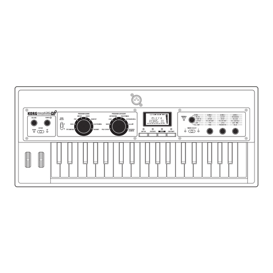
microKORG XL+ 2. Front and rear panels Front panel 7 8 9 10 1. [VOLUME] knob 4. [BANK SELECT] lever This adjusts the volume of the OUTPUT jacks (L/MONO, R) and head- This selects the program bank. phone jack. 5. [PROGRAM GENRE] dial 2. - Page 7 Introduction 8. [VOCODER] (AUDIO IN THRU) button 15. Display This turns the vocoder on/off ( p. 13). (When on, the LED above the but- Information on the selected program is shown here. In full edit mode, the ton will be lit.) display shows the selected page, the current value of the parameter, vari- By holding down the [EXIT/SHIFT] button and pressing this button, you can ous messages, or other information.
-
Page 8: Rear Panel
3. AUDIO IN [LINE] jack microKORG XL+’s parameters. This is a monaural audio input jack. Use the AUDIO IN [LEVEL] knob to In order to use a USB connection, you’ll need to install the Korg USB- NOTE adjust the level. -
Page 9: Preparations
USB/MIDI or the onboard MIDI connections.( p. 80 “1.Using the micro- You must make connections with the power turned off. Failure to KORG XL+ with other MIDI devices (MIDI)”). observe this precaution may cause malfunctions or damage to your speaker system. -
Page 10: Turning The Power On
Depleted batteries should be immediately removed from the micro- 2. Connect the included AC adapter to the DC9V jack located KORG XL+. Leaving depleted batteries installed may cause mal- on the rear panel. functions (such as leakage of the battery electrolyte). You should ’... -
Page 11: Turning The Power Off
Preparations Turning the power off After completing any necessary operations such as saving your edited pro- gram, turn off the power using the following procedure. Never turn off the power while data is being saved (i.e., while execut- ing the Write operation). Doing so may destroy internal data. 1. -
Page 12: Quick Start
microKORG XL+ Quick start 2. Selecting and playing a program Playing a synthesizer program The microKORG XL+ contains 128 programs that you can play immedi- 1. Demo performance ately. To select a program, you’ll use the panel PROGRAM GENRE dial, PRO- GRAM CATEGORY dial, and BANK SELECT lever. -
Page 13: Playing A Vocoder Program
Quick start 5. Adjust the mic input level. Playing a vocoder program While vocalizing into the mic, turn the AUDIO IN [LEVEL] knob toward the A vocoder modifies the signal from an oscillator or other source (the “car- right as far as possible without allowing the “CLIP” indication to appear in rier”) by applying the spectral characteristics of an external input source the level meter shown to the right of the display. -
Page 14: Modifying The Sound
microKORG XL+ Using the keyboard to modify the sound 3. Modifying the sound Velocity To make your performance more expressive, you can modify the sounds of The effect will vary depending on the amount of force that you play the keys the microKORG XL+ by using the [1]–[3] knobs, the [PITCH] wheel, the with. - Page 15 Quick start Using the [OCTAVE] lever to switch octaves The area of pitches assigned to the keyboard can be changed in one- octave steps over a range of +/–3 octaves. Lever operation Keyboard range Key LED Lever operation Move toward Move toward C6–C9 UP LED lit red...
-
Page 16: Using The Knobs To Modify The Sound
microKORG XL+ Some of the main parameters you can control using performance edit are Using the knobs to modify the sound described below. When the [KNOB FUNCTION SELECT] dial is set to “ASSIGN,” “FILTER,” CUTOFF “AMP EG,” “EFFECT,” or “ARP,” you can use knobs [1]–[3] to control the This adjusts the cutoff frequency of filter 1, varying the brightness of the performance edit functions. - Page 17 Quick start Knob [3] (FX1 CONTROL 1) Level This adjusts the parameter that’s assigned to CTRL-1 (FX1 CONTROL 1) for the effect used by the currently selected program. Note off Note on You are free to change the parameter that’s assigned to this knob. Refer NOTE to page 63 “Controlling effect parameters.”...
-
Page 18: Playing Arpeggios
microKORG XL+ 5. To stop the arpeggio, press the [ARP ON] button (the LED 4. Playing arpeggios goes dark). Using the arpeggiator The arpeggiator is a function that automatically plays a broken chord (arpeggio) when you hold down a chord on the keyboard. The microKORG XL+’s arpeggiator provides six arpeggio types, and allows you to change various aspects of the arpeggio, such as the duration (gate time) of the notes. -
Page 19: Editing The Sound
Editing the sound Editing the sound The three elements of sound: pitch, tone, and volume Sound has three basic elements: pitch, tone, and volume. Just like the ana- log synthesizers of the past, the microKORG XL+ analog modeling synthe- sizer provides “oscillator,” “filter,” and “amp” (amplifier) sections that control these three elements. - Page 20 microKORG XL+ Oscillator (OSC1, OSC2, NOISE) Envelope generators (EG1, EG2, EG3) Oscillator 1 (OSC1) lets you choose from seven types of oscillator algo- An envelope generator applies time-variant change to parameters that rithm such as the sawtooth wave or square wave familiar from analog syn- make up the sound.
-
Page 21: Vocoder
Editing the sound Arpeggiator (ARPEGGIATOR) Audio In The arpeggiator automatically generates an arpeggio (broken chord) when you hold down a chord on the keyboard. For programs that use two tim- Vocoder Sw= ON Synth Timbre 1 bres, you can apply the arpeggiator to either or both timbres. This is a step Carrier Vocoder arpeggiator with six arpeggio types. -
Page 22: Basic Editing Procedure
microKORG XL+ Carrier (CARRIER) The most suitable choice as a carrier is a waveform that contains large 2. Basic editing procedure numbers of overtones, such as a sawtooth wave or pulse wave. The output of timbres 1 and 2 is mixed and used as the carrier. There are two ways to edit sounds on the microKORG XL+. -
Page 23: Full Edit Mode
Editing the sound About the display in Full Edit mode 3. Full Edit mode When you turn knob [1] to select the OSC1 page, the upper line of the dis- play will indicate the name of the page, and the lower line will indicate the name of a parameter. -
Page 24: Editing The Two Timbres
microKORG XL+ If the parameter value does not change when you turn the knob Restoring an edited program value to its original setting In some cases when you’ve used the [KNOB FUNCTION SELECT] dial to When you set a value to the same value stored in the original preset pro- choose a section to edit, turning knobs [1]–[3] may not change the value of gram or saved program, the ORIGINAL VALUE LED will light. -
Page 25: Editing The Vocoder
Editing the sound 4. Use knob [1] to select one of the VC CARRI–VC BAND The LED of the selected timbre will light-up, and that timbre will be the one affected by your editing. pages, and then use knobs [2] and [3] to edit the vocoder The TIMBRE SELECT LED won’t light if the COMMON page “VO- NOTE parameters. -
Page 26: Editing The Arpeggiator
microKORG XL+ 3. Connect an audio signal from your external device to the Modifying the arpeggio input, and adjust the AUDIO IN [LEVEL] knob as high as You can modify the arpeggio by turning each arpeggio step on/off. This is possible without allowing the “CLIP”... -
Page 27: About The Global Settings
Editing the sound 3. Use knob [3] to turn the selected step on/off. In the display, enabled steps are indicated as “O” (on). If you turn knob [3] 4. About the Global settings to change the indication to “–” (off), that step will be a rest. The GLOBAL parameters are settings that apply to the entire microKORG XL+. -
Page 28: Other Functions
NOTE The “MIDI Implementation” including details on the MIDI exclusive format NOTE can be downloaded from the Korg website. Copying a timbre Do not touch the microKORG XL+’s knobs or keyboard while data is Here’s how to copy timbre settings from another program to the timbre of being transmitted or received. -
Page 29: Restoring The Factory Settings
Do not touch the microKORG XL+’s knobs or keyboard while the sent back to the microKORG XL+, or data received from another micro- Preload operation is in progress. Never turn off the power during this KORG XL+ unit. operation. 1. Connect the microKORG XL+’s MIDI IN connector to the You can’t execute the Preload operation if Write Protect is turned on. - Page 30 microKORG XL+ 2. Use knob [2] to select the desired type of preload data. 1 PROG: Only the data for the currently selected program will be loaded (the parameters of the NAME–VC BANK pages and the settings of the front panel buttons and knobs).
-
Page 31: Saving (Writing)
Saving (Writing) 4. Press the [WRITE] button to write the data. Saving (Writing) The display will indicate “COMPLETE,” at this point the Write operation will be completed, and the microKORG XL+ will return to its normal state. If you decide to cancel the operation, press the [EXIT/SHIFT] button. If the display indicates “ERROR”... -
Page 32: Parameter Guide
microKORG XL+ Parameter Guide VOIC.MODE..........[SINGLE, LAYER, SPLIT, MULTI] This parameter determines how many timbres a program will use, and how those timbres will be allocated. SINGLE: Only one timbre will be used. 1. Timbre parameters NAME LAYER: Two timbres will be used. When you play the keyboard, both tim- bres will sound simultaneously. - Page 33 Parameter Guide T2MIDI.CH (Timbre 2 MIDI channel) ......[GLOBAL, 01…16] SCALE ................[EQUAL…USER] When the “VOIC.MODE” is set to either Layer or Multi, this parameter can Selects the type of scale that the current program will use. You can choose be used to set the MIDI channel for timbre 2. one of ten different scale types.
- Page 34 microKORG XL+ You can make assignments for knobs [1]–[3] independently for timbre 1 and LEVEL Level timbre 2; the knobs will control the timbre that’s selected by the [TIMBRE SELECT] lever. PANPOT Panpot With the factory settings, suitable parameters are already assigned to the NOTE WS DEPTH Wave Shape Depth...
- Page 35 Parameter Guide DETUNE (Unison Detune)............. [0...99] GATE.TIME Arpeggiator Gate Time This parameter is available when Unison is on (i.e., if “MODE” is 2–4 OCT.RANGE Arpeggiator Octave Range Voice). It specifies (in units of cents) the amount of detuning that will occur between the stacked voices.
- Page 36 microKORG XL+ TRANSPOS (Transpose)............[–48...+48] WAVE (Waveform Select)................ Adjusts the pitch of the oscillators in semitone steps. [SAW, PULSE, TRIANGLE, SINE, FORMANT, NOISE, PCM/DWGS, AUDIO IN] The range is four octaves upward or downward. Selects the waveform for oscillator 1. The Saw, Pulse (square), Triangle This setting is related to the pitch of the oscillators themselves;...
- Page 37 Parameter Guide UNISON: Unison simulates skewing the pitch of five stacked oscillators lowing table when assigning OSC1.C1 or OSC1.C2 to “virtual patch,” from within a single oscillator, to create a richer sound. “KNOB,” or GLOBAL “CC MAP.” Unison Detune WAVE OSC MOD C1 (OSC1 Control 1) C2 (OSC1 Control 2)
- Page 38 microKORG XL+ • WAVE: SINE 1. When Wave: Saw, Pulse, Triangle, Sine and OSC1 Mod: Waveform Sine wave is a mild tone that contains only the fundamental frequency with no overtones. A setting of 000 produces a simple sine wave. Increasing this Control1: WAVEFORM............[000…127] value will modify the waveform, changing the overtone structure as shown This modifies the waveform.
- Page 39 Parameter Guide 3. When Wave: Noise, and OSC1 Mod: Waveform PCM/DWGS Name PCM/DWGS Name GUITAR2 DIGI3 Control1: Resonance ............[000…127] BASS1 DIGI4 This parameter adjusts the amount of resonance of the filter provided within BASS2 DIGI5 the noise oscillator. Higher values will emphasize the frequency points for BASS3 DIGI6 the pitched component within the noise.
- Page 40 microKORG XL+ Control2: LFO 1 Intensity ............[000…127] 8. When Wave:Saw, Pulse, Triangle, Sine and OSC1 Mod: VPM This parameter adjusts the depth of the additional modulation applied by Control1: Modulation Depth..........[000…127] LFO1 to the cross modulation effect. Adjusts the depth of VPM. 7.
- Page 41 Parameter Guide RING: Oscillator 2 will be used as a ring modulator. By adjusting “SEMI- SEMITONE (Oscillator 2 Semitone) ..........[–24...24] TONE” or “TUNE” you can create metallic sounds with little sense of pitch. Specifies the detuning (pitch difference) relative to oscillator 1, in semitone This is useful for sound effects.
- Page 42 - either above (Low Pass), below (High-Pass), or centered on (Band Pass) the cutoff frequency. The micro- KORG XL+ has two filters (filter 1 and filter 2), and you can change their routing to create more complex filter sounds.
- Page 43 Parameter Guide ROUTING..........[SINGLE, SERIAL, PARALLEL, INDIV] EG1 INT (EG1 Intensity/Filter1) ..........[–63...63] Specifies the routing (connection) between filter 1 and filter 2. This specifies how time-variant modulation from the EG1 will be applied to the cutoff frequency. SINGLE Only filter 1 is used. Filter 1 and filter 2 are connected in series.
- Page 44 microKORG XL+ Increasingly negative (–) settings will allow a correspondingly greater effect FILTER2 in the opposite direction. Here you can adjust the settings of the filter 2 parameters. The FILTER1 Cutoff page “ROUTING” parameter specifies how filter 2 and filter 1 will be con- nected.
- Page 45 Parameter Guide With positive (+) settings, the volume will increase as you play above the Flattens any portion of the waveform above the limit. C4 note on the keyboard, and will decrease as you play below C4. DEPTH: 000 DEPTH: 064 DEPTH: 127 With negative (–) settings, the volume will decrease as you play above the C4 note on the keyboard, and will increase as you play below C4.
- Page 46 microKORG XL+ such as this are an important aspect of how we identify the sound of a spe- POSITION ............... [PRE FILT1, PRE AMP] cific instrument. This type of change also occurs in the tone and pitch, as Specifies the position at which the drive or wave shape functions will be well as in the volume.
- Page 47 Parameter Guide VEL INT (Velocity Intensity)........... [–63...+63] VEL INT (Velocity Intensity) ...........[–63...+63] This specifies how your keyboard velocity (playing strength) will affect the This specifies how your keyboard velocity (playing strength) will affect the amplitude of EG1. Higher settings of this parameter will allow changes in amplitude of EG2.
- Page 48 microKORG XL+ LFO (Low Frequency Oscillator) Note on The LFO (Low Frequency Oscillator) is an oscillator that produces a rela- tively slow (low-frequency) oscillation, and is used to apply cyclic modula- tion to various aspects of the sound. Some typical ways to use LFO are vibrato (use LFO to raise and lower the pitch), wah (use LFO to raise and lower the cutoff frequency), and tremolo (use LFO to raise and lower the TIMBRE: The phase of the LFO will be reset by the first note-on that occurs...
- Page 49 (“patched”) by a patch cord to any other module as desired, allowing you a LEVEL The AMP page “LEVEL”. great deal of freedom in creating the sound. The Korg MS Series (MS-20, PANPOT The AMP page “PANPOT”. MS-50, MS-10, etc.) went on sale in 1978 and featured this type of patch- LFO1.FREQ...
- Page 50 microKORG XL+ Setting example for “SOURCE” and “DEST” EG1 INT2 The FILTER2 page “EG1 INT”. KEY TRK2 The FILTER2 page “KEY TRK”. SOURCE [1] DEST [2] ATTACK1 The EG1 page “ATTACK”. The EG1 or EG2 will vary the pitch of the entire timbre over DECAY1 The EG1 page “DECAY”.
-
Page 51: Arpeggio Parameters
Parameter Guide Negative (–) values cut the region below the cutoff frequency. 2. Arpeggio parameters HI FREQ (High EQ Frequency)......... [1.00…20.0kHz] Specifies the cutoff frequency of the high equalizer. Front Panel Arpeggio Parameters HI GAIN (High EQ Gain)..........[–15.0…+15.0dB] Specifies the gain of the high equalizer. [TEMPO] knob Positive (+) values boost the region above the cutoff frequency. - Page 52 microKORG XL+ DOWN: Notes will be played consecutively from high pitches to low. TRIGGER: The notes you are holding down will be played simultaneously at the tempo and “RESOLUTN” timing. The “OCT.RANGE” setting will be ignored. ALT1: Up and Down will be alternated. (The highest and lowest notes will be played once.) If you are holding down more notes than the maximum polyphony of the NOTE...
- Page 53 Parameter Guide SWING (Arpeggiator Swing) .........[–100%...+100%] TRIGGER...................[OFF, ON] Specifies the percentage (%) by which even-numbered notes of the arpeg- Specify the on/off status of each step 1–8. gio will be shifted in timing relative to the first note. The number of available steps is specified by the “LAST.STEP” setting. –...
-
Page 54: Edit Utility Parameters
microKORG XL+ 3. Edit utility parameters 4. Vocoder parameters Front panel vocoder parameters UTILITY Here are program-related utility functions. [VOCODER] button This switches the Vocoder function on/off. INIT.PROG (INITIALIZE PROGRAM)............Off (LED unlit): Vocoder is off. The program will not use the vocoder. This initializes the settings of the selected program. - Page 55 Parameter Guide TIMBRE2: The output of timbre 2 will be input to the modulator. VC FILT (Vocoder Filter) GATE.SENS (Gate Sensitivity) ..........[000...127] Here you can adjust the settings for the carrier’s sixteen band-pass filters Specifies the speed at which the gate will operate according to the and modulator’s envelope filter.
- Page 56 microKORG XL+ VC BAND (Vocoder Band) RESO (Vocoder Resonance)............. [000...127] This specifies the amount of resonance for each of the carrier’s sixteen These parameters specify the output level and panning (stereo position) for band-pass filters (the synthesis filter). Higher settings will boost the sound each of the carrier’s sixteen band-pass filters (the synthesis filter).
-
Page 57: Global Parameters
The settings you make from the global screen will apply to the entire micro- KORG XL+, such as the overall tuning and the velocity curve. MST TUNE (Master Tune) ..........[430.0...450.0Hz] (127) Adjusts the overall pitch in 0.1 Hz steps, in terms of A4 as the reference... - Page 58 microKORG XL+ POSITION ..............[POST KBD, PRE TG] PROTECT ..................[OFF, ON] Specifies the internal MIDI IN/OUT routing within the microKORG XL+. This specifies whether internal memory will be protected. This setting will affect the way in which MIDI data is transmitted and OFF: You’ll be able to write to internal memory.
-
Page 59: Midi Parameters
XL+ KBD/KNOB USB MIDI TX (INT) MIDI OUT KORG XL+ is connected to a sequencer and the performance data is USB MIDI TX (EXT) microKORG XL+ MIDI IN echoed back from the sequencer. (Echo back is when the performance... - Page 60 microKORG XL+ CLOCK..........[AUTO, INTERNAL, EXT USB, EXT MIDI] SYS EX (System Exclusive) ..........[DISABLE, ENABLE] Specifies how the microKORG XL+ will synchronize with an external MIDI Selects whether MIDI system exclusive messages will be transmitted and device (sequencer, rhythm machine, etc.). If the LFO 1/2 or delay effect received.
- Page 61 +63: The note will be 63 cents sharper than standard pitch. will produce a modulation effect of 0 on the micro- KORG XL+. If you’ve selected #016, #017, #019, #020, or #021, setting the slider etc. to a position of 0 (control change value 0) will produce a modulation effect of 0 on the microKORG XL+.
-
Page 62: Global Utility Parameters
microKORG XL+ 7. Global utility parameters UTILITY Here are utility functions for the microKORG XL+’s data. MIDI.DUMP (MIDI DATA DUMP) ..[1 PROG, ALL PROG, GLOBAL, ALL DATA] You can transmit programs or global data as MIDI exclusive data so that it can be saved on a connected MIDI data filer or computer. -
Page 63: Effect Guide
Effect guide Then use each effect’s “DRY/WET” or “OUT.LEVEL” parameters to adjust Effect guide the output level of the effect. Some effect types do not have a “TRIM” or “OUT.LEVEL” parameter. There is no input level meter etc. to check the input level to the effect. -
Page 64: About The Delay Time
microKORG XL+ About the delay time TM RATIO (Time Ratio) For delay effects, the actual delay time will be the delay time multiplied by the “TM RATIO.” For example, • If “BPM SYNC”: Off, “L DELAY”: 0800ms, “R DELAY”: 0400 ms, and “TM RATIO”: 50%, then the actual delay time will be 400 ms in the left channel and 200 ms in the right channel. -
Page 65: Effect Parameters
Effect guide Compressor - Sensitivity Level 2. Effect Parameters Sensitivity=100 Sensitivity=40 • [Parameter name] : These are the parameters that can be assigned to [CTRL-1] or [CTRL-2]. ( p. 63 “Effect knob assignments”) Time 1. COMPRESR (Stereo Compressor) ATTACK ..............[000.1…500.0ms] Sets the attack level. - Page 66 microKORG XL+ FLT TYPE (Filter Type)................LFO FREQ (LFO Frequency) ......... [0.01…100.0Hz] Sets the LFO speed. [LPF24 (–24dB/oct), LPF18 (–18dB/oct), LPF12 (–12dB/oct), HPF12 Increasing this value will result in a faster frequency. (–12dB/oct), BPF12 (–12dB/oct)] This parameter will be displayed and can be set if “MOD SRC” is LFO NOTE Selects the filter type.
- Page 67 Effect guide KEY SYNC (LFO KeySync) ............[OFF, ON] Source Explanation Specifies how the LFO will be reset at note-on. Not used This parameter will be displayed and can be set if “MOD SRC” is LFO. NOTE VELOCITY Velocity Note on P.BEND Pitch bend MOD.WHEEL...
- Page 68 microKORG XL+ B1 TYPE ..............[PEAKING, SHELV LO] B4 FREQ (B4 Frequency) ..........[20Hz…20kHz] Selects the EQ type of Band 1. Sets the center frequency of Band 4. Band1/ Band4 Type B4 Q ................. [00.5…10.0] +Gain Band4 Type=Shelving High Sets the bandwidth of Band 4. Band4 Type=Peaking Band1 Type=Shelving Low B4 GAIN...
- Page 69 Effect guide B1 FREQ (B1 Frequency)..........[20Hz…20kHz] Stereo In - Stereo Out Sets the center frequency of Band 1. Left Dry / Wet High Damp Output Level Pre LPF B1 Q ..................[00.5…10.0] Decimator Sets the bandwidth of Band 1. Sampling Frequency B1 GAIN ...............
- Page 70 microKORG XL+ FS.MOD.INT (Fs Modulation Intensity) .......[–63…+63] Stereo In - Stereo Out Sets the depth of sampling frequency LFO modulation. Left Dry / Wet High Damp Delay LFO SYNC (LFO Tempo Sync) ............[OFF, ON] Trim Specifies whether the LFO cycle will synchronize to the tempo specified by Stereo/Cross Feedback Spread...
- Page 71 Effect guide FEEDBACK ...............[000…127] TM RATIO ........[BPM SYNC OFF: 000.5…400.0% (OVER) Sets the amount of feedback for the left and right channels. /BPM SYNC ON: 012.5…400.0% (OVER)] The amount of feedback for the right channel is linked with the proportion of Sets each delay time as a proportion relative to the “L DELAY,”...
- Page 72 microKORG XL+ SYNC .NOTE (LFO Sync Note) ..........[8/1…1/64] Stereo In - Stereo Out Sets the LFO frequency as a proportion of the tempo set by the [TEMPO] Left Dry / Wet knob. High Damp Delay This parameter will be displayed and can be set if “LFO Sync” is On. NOTE Trim ...
- Page 73 Effect guide Stereo In - Stereo Out Wet: Mono In - Stereo Out / Dry: Stereo In - Stereo Out Left Dry / Wet Left Dry / Wet Delay Feedback Tap1 Level Feedback Tape Delay Spread Saturation Trim Pre Tone High / Low Damp Tap2 Level Delay...
- Page 74 microKORG XL+ SATURATN (Tape Saturation) ..........[000…127] LFO FREQ (LFO Frequency) ......... [0.01…100.0Hz] Sets the distortion amount. Sets the LFO speed. Increasing this value will result in a faster frequency. WOW.FREQ (Wow Flutter Frequency) ......[0.01…100.0Hz] LFO SPRD (LFO Spread)............[–180…180°] Sets the frequency at which pitch variation will occur in Hz steps.
- Page 75 Effect guide 13. VIBRATO (Stereo Vibrato) FEEDBACK ...............[000…127] Sets the amount of feedback for the left and right channels. This effect causes the pitch of the input signal to shimmer. Using the Auto- Fade allows you to increase or decrease the shimmering speed. PHASE ..................[+, –] This switches the phase of the output and feedback.
- Page 76 microKORG XL+ LFO SHAPE ................[–63…+63] MOD.DEPTH (Modulation Depth) ........[000…127] p. 66 “LFO.SHAPE” Sets the depth of LFO modulation. KEY SYNC (LFO KeySync) ............[OFF, ON] RESO (Resonance) ............[000…127] Specifies whether the LFO will be reset by note-on. Sets the resonance amount. ...
- Page 77 Effect guide LFO SPRD (LFO Spread)............[–180…+180°] SYNC.NOTE (LFO Sync Note) ..........[8/1…1/64] Sets the LFO phase difference between the left and right channels. Sets the LFO frequency as a proportion of the tempo set by the [TEMPO] knob. HI DAMP ................[000…100%] This parameter will be displayed and can be set if “LFO SYNC”...
- Page 78 microKORG XL+ OSC WAVE (OSC Waveform) ........[SAW, TRIANGLE, SINE] Stereo In - Stereo Out Selects the ocsillator waveform. Left Dry / Wet Pre LPF Ring Modulator LFO INT (LFO Intensity) ........... [–63…+63] Sets the depth of LFO modulation. Pre LPF Ring Modulator LFO SYNC (LFO Tempo Sync) ............[OFF, ON] Specifies whether the LFO cycle will be synchronized with the tempo speci-...
- Page 79 Effect guide 17. GRAIN.SFT (Grain Shifter) LFO SYNC (LFO Tempo Sync) ............[OFF, ON] Specifies whether the LFO cycle will be synchronized with the tempo speci- This effect samples extremely brief fragments of the sound at a specified fied by the [TEMPO] knob or MIDI clock. interval, and plays them as a loop.
-
Page 80: Midi
microKORG XL+ Controlling the microKORG XL+’s tone generator from an exter- MIDI nal MIDI device When you want to play or control the microKORG XL+’s tone generator from an external MIDI keyboard or sequencer etc., use a MIDI cable to con- nect the MIDI OUT connector of the external MIDI device to the MIDI IN connector of the microKORG XL+. -
Page 81: Midi-Related Settings
PC editor software. 4. To set the MIDI channel for timbre 1, select the MIDI page “MIDI CH” In order to use a USB connection, you must install the Korg USB-MIDI NOTE parameter, and use knob [3]. - Page 82 MIDI sequencer / computer, and connect the micro- received. ( p. 60) KORG XL+’s MIDI IN connector to the MIDI OUT connector of your external MIDI sequencer / computer. Then turn the microKORG XL+’s Virtual patch modulation source settings Local Control off (MIDI page “LOCAL”...
-
Page 83: Midi Messages
MIDI channel. The global MIDI channel is the basic MIDI channel used by the micro- NOTE KORG XL+ to transmit and receive MIDI data. It is specified by the MIDI page setting “MIDI CH”. Note-on/off Note-on [9n, kk, vv], Note-off [8n, kk, vv]... -
Page 84: Program Change, Bank Select
microKORG XL+ When you move the [PITCH] wheel on the microKORG XL+, pitch bend Program change, Bank select change messages are transmitted on the Global MIDI channel. If you want pitch bend changes to be transmitted and received, set the MIDI Program change [Cn, pp] FLT page “P.BEND”... - Page 85 MIDI • Expression (CC#11) [Bn, 0B, vv] Assigning a control change to a knob or button When expression messages are received, the volume of a timbre will be In the CC MAP page, you can assign the control changes CC#00–CC#95 controlled.
-
Page 86: Parameters Transmitted And Received Via Nrpn
microKORG XL+ Value (transmitted) Value (received) (Hex) (Hex) 3. Parameters transmitted and received ON/OFF 00(00) 02(02) 0: OFF, 127: ON 0...63: OFF, 64...127: ON LATCH 00(00) 04(04) 0: OFF, 127: ON 0...63: OFF, 64...127: ON via NRPN 0...21: Up, 22...42: Down, 0...21: Up, 22...42: Down, 43...63: Alt1, 64...85: Alt2, 43...63: Alt1, 64...85: Alt2,... -
Page 87: Controlling The Timbre Parameters
MIDI GATE values Controlling the Timbre parameters These messages are transmitted and received on the Global MIDI channel. Value Gate Value Gate Value Gate Value Gate (transmitted, Time (transmitted, Time (transmitted, Time (transmitted, Time Controlling the Virtual Patch1…Patch6 Source received) received) received) received) -
Page 88: Controlling The Vocoder Parameters
microKORG XL+ Controlling the vocoder parameters Controlling the Virtual Patch1…Patch6 Destination • Dest1…Dest6: [Bn, 63, 04, Bn, 62, 08…0D, Bn, 06, mm] These messages are transmitted and received on the Global MIDI channel. (n: channel, mm: parameter value) Fc Modulation Source Value (transmitted) Value (received) (Hex) -
Page 89: Other Controls
Other controls When master fine tuning is received, the value specified for the micro- KORG XL+’s GLOBAL page “MST TUNE” will be ignored, and the overall These messages are transmitted and received on the Global MIDI channel. pitch will be specified by the data that was received. -
Page 90: Front Panel Knob/Button Control Change Assignments
microKORG XL+ If you are using two microKORG XL+ units to transmit and receive these parameters, you must set the transmitting and receiving pro- 4. Front panel knob/button control grams to the same settings. change assignments Control changes can be assigned to each front panel knob/button of the microKORG XL+ so that the changes in sound as controlled by knob/but- ton operations can be transmitted as performance data. - Page 91 MIDI CUTOFF CC#30 0...127 0...127 RESO CC#68 0...127 0...127 FILTER2 TYPE CC#29 0...42: LPF, 43...83: HPF, 85...127: BPF 0...42: LPF, 43...83: HPF, 85...127: BPF EG1 INT CC#69 0/1: –63, 2: –62...63: –1, 64: 0, 65: +1...127: +63 0/1: –63, 2: –62...63: –1, 64: 0, 65: +1...127: +63 KEY TRK CC#82 0/1: –2...
- Page 92 microKORG XL+ FRMNT.SFT 0...25: –2, 26...51: –1, 52...76: 0, 77...102: +1, 103...127: +2 0...25: –2, 26...51: –1, 52...76: 0, 77...102: +1, 103...127: +2 FC.OFFSET 0/1: –63, 2: –62...63: –1, 64: 0, 65: +1...127: +63 0/1: –63, 2: –62...63: –1, 64: 0, 65: +1...127: +63 VC FILT RESO 0...127...
- Page 93 MIDI “SYNC.NOTE” value when LFO 1/2 or DELAY “BPM SYNC” = ON “EQ Gain” values If BPM SYNC is on, the “FREQ” parameter of LFO 1/2 and the delay The following table shows the correspondence between the parameter parameter of the master effects will change to “SYNC.NOTE.” In conjunc- value and control change value transmitted/received when you adjust the tion with this, the correspondence between the parameter value and the EQ page “GAIN”...
-
Page 94: Appendices
microKORG XL+ Appendices Can’t input sound Is the input source connected to the AUDIO IN [LINE] jack or [MIC] jack? If you’re using the AUDIO IN [MIC] jack, is the [XLR/LINE] switch set to XLR? 1. Trouble shooting If you’re using the AUDIO IN [LINE] jack, is the [XLR/LINE] switch set to LINE? Before you suspect a malfunction, please check the following points. - Page 95 Appendices Can't write programs or global settings Is the GLOBAL page PROTECT setting OFF? If the edited program or global setting did not remain, did you use knob [1] to specify the data to be saved when you executed the Write opera- tion? Arpeggiator will not start ...
-
Page 96: Program List
microKORG XL+ Program Name Genre Category Arpeggio 2. Program List SLIP PAD DANCE POLY SYNTH SATISFAC DANCE BASS 8VESAW DANCE LEAD Program Name Genre Category Arpeggio BUILDER DANCE ARP/MOTION ANALOG 70'S VINTAGE POLY SYNTH EVOLTION DANCE PAD/STRINGS MG BASS 70'S VINTAGE BASS M1 ORGAN DANCE... - Page 97 Appendices Program Name Genre Category Arpeggio Program Name Genre Category Arpeggio Z-FIELD 70'S VINTAGE ARP/MOTION 2MANYOSC DANCE S.E./HIT SOLINSTR 70'S VINTAGE PAD/STRINGS VOC FLNG DANCE VOCODER/AUDIO IN WURLY EP 70'S VINTAGE KEYBOARD/BELL SCREAMER DUBSTEP POLY SYNTH INSPACE 70'S VINTAGE S.E./HIT TECHSTEP DUBSTEP BASS...
-
Page 98: Demo Song
SNOW KORG Inc. RADIOTEK KORG Inc. TLKBOXER KORG Inc. EVOLTION Henning Verlage PREVIEW4 H.V. x KORG Inc. All Demo Songs: ©2012 KORG Inc. —All rights reserved. For more information about the authors please visit : Katsuyuki Mito (http://mito310.seesaa.net/) Henning Verlage(www.facebook.com/henningverlage) -
Page 99: Specifications
Appendices Input/output Input AUDIO IN [LINE] jack, AUDIO IN [MIC] jack 4. Specifications AUDIO IN [LINE] jack Maximum input level -17 dBu @ GAIN: Max. Sound generation system Input impedance 7k-ohms MMT (Multiple Modeling Technology) Connector 1/4" phone jack (unbalanced) Programs AUDIO IN [MIC] jack Number of timbres Maximum 2 (when using Layer, Split, or Multi) -
Page 100: Index
microKORG XL+ Envelope generators ......20 MIDI parameter........59 Sine wave ..........38 5. Index EQ ............20, 51 Mixer ............20 SINGLE ............32 Equalizer .........20, 51 Modulator SPLIT............32 External audio input ......26 (MODULATOR)....21, 22, 25 Step arpeggiator.........26 MULTI ............. 32 Synthesizer..........19 Multi-timbral........ - Page 101 Appendices...
- Page 102 microKORG XL+...
- Page 103 WARNING: Use of this product in any country other than that for which it is intended could be dangerousand could invalidate the manufacturer’s or distributor’s warranty. Please also retain your receipt as proof of purchase otherwise your product may be disqualified from themanufacturer’s or distributor’s warranty. 4015-2 Yanokuchi, Inagi-city, Tokyo 206-0812 Japan © 2012 KORG INC.
Need help?
Do you have a question about the MMT microKORG XL+ and is the answer not in the manual?
Questions and answers