Table of Contents
Advertisement
Advertisement
Table of Contents

Related Manuals for Korg Microkorg XL


Summary of Contents for Korg Microkorg XL
- Page 2 Then contact your nearest tact your local administrative body for details. If the battery Korg dealer or the store where the equipment was pur- contains heavy metals in excess of the regulated amount, chased.
-
Page 3: Table Of Contents
Table of Contents Table of Contents Editing the sound........19 1. How a program is organized ......19 Synthesizer....................19 Vocoder ....................21 Introduction ........... 5 2. Basic editing procedure........22 1. Main features............. 5 Editing a program ..................22 3. Full Edit mode..........23 2. - Page 4 2. Effect Parameters ........... 65 2. Program List ............96 3. Demo Song............98 MIDI ............. 80 4. Specifications and options......99 1. Using the microKORG XL with other MIDI 5. Index ...............100 devices (MIDI)..........80 Connecting MIDI devices/computers ............80 MIDI-related settings ................81 2.
-
Page 5: Introduction
Controllers such as EG, LFO, keyboard tracking, and the wheels can be vir- tually connected to parameters such as pitch or cutoff, allowing you to mod- Thank you for purchasing the Korg microKORG XL. In order to take full ulate these parameters and create sounds with a high degree of freedom. -
Page 6: Front And Rear Panels
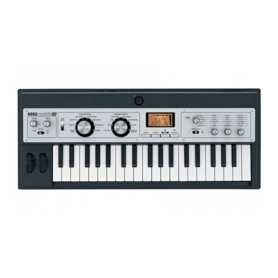
XL 2. Front and rear panels Front panel 7 8 9 10 1. [VOLUME] knob 4. [BANK SELECT] lever This adjusts the volume of the OUTPUT jacks (L/MONO, R) and head- This selects the program bank. phone jack. 5. [PROGRAM GENRE] dial 2. - Page 7 Introduction 8. [VOCODER] (AUDIO IN THRU) button 15. Display This turns the vocoder on/off ( p. 13). (When on, the LED above the but- Information on the selected program is shown here. In full edit mode, the ton will be lit.) display shows the selected page, the current value of the parameter, vari- By holding down the [EXIT/SHIFT] button and pressing this button, you can ous messages, or other information.
-
Page 8: Rear Panel
9. [DC 9V] connector jack on the front panel. Connect the included AC adapter here. Connect the AC adapter to the microKORG XL before you plug it into an 5. AUDIO IN [LEVEL] knob AC outlet. This adjusts the input level from the AUDIO IN [MIC] or [LINE] jacks. -
Page 9: Preparations
1. Connections Connect your mic or sampler to the input jack If you’re using the microKORG XL as a vocoder, connect the mic to the The illustration below shows a typical example of connections for the AUDIO IN [MIC] jack so that the mic audio can be used as a modulator microKORG XL. -
Page 10: Turning The Power On
Before you power-on the microKORG XL, you must power-off any external output device such as your powered monitor speakers. Using batteries 1. Turn the microKORG XL’s [VOLUME] knob all the way to The microKORG XL can also operate on batteries. the left. -
Page 11: Turning The Power Off
1. Lower the volume of your powered monitor speakers or other external output device, and then turn off their power. 2. Turn the [VOLUME] knob of the microKORG XL all the way toward the left, and then press the power switch to turn off... -
Page 12: Quick Start
Quick start 2. Selecting and playing a program Playing a synthesizer program The microKORG XL contains 128 programs that you can play immediately. 1. Demo performance To select a program, you’ll use the panel PROGRAM GENRE dial, PRO- GRAM CATEGORY dial, and BANK SELECT lever. -
Page 13: Playing A Vocoder Program
Quick start 5. Adjust the mic input level. Playing a vocoder program While vocalizing into the mic, turn the AUDIO IN [LEVEL] knob toward the A vocoder modifies the signal from an oscillator or other source (the “car- right as far as possible without allowing the “CLIP” indication to appear in rier”) by applying the spectral characteristics of an external input source the level meter shown to the right of the display. -
Page 14: Modifying The Sound
The effect will vary depending on the amount of force that you play the keys the microKORG XL by using the [1]–[3] knobs, the [PITCH] wheel, the with. Normally, the force of your strike will affect the tone or volume. - Page 15 Quick start Using the [OCTAVE] lever to switch octaves The area of pitches assigned to the keyboard can be changed in one- octave steps over a range of +/–3 octaves. Lever operation Keyboard range Key LED Lever operation Move toward Move toward C6–C9 UP LED lit red...
-
Page 16: Using The Knobs To Modify The Sound
XL Some of the main parameters you can control using performance edit are Using the knobs to modify the sound described below. When the [KNOB FUNCTION SELECT] dial is set to “ASSIGN,” “FILTER,” CUTOFF “AMP EG,” “EFFECT,” or “ARP,” you can use knobs [1]–[3] to control the This adjusts the cutoff frequency of filter 1, varying the brightness of the performance edit functions. - Page 17 Quick start Knob [3] (FX1 CONTROL 1) Level This adjusts the parameter that’s assigned to CTRL-1 (FX1 CONTROL 1) for the effect used by the currently selected program. Note off Note on You are free to change the parameter that’s assigned to this knob. Refer NOTE to page 63 “Controlling effect parameters.”...
-
Page 18: Playing Arpeggios
The arpeggiator is a function that automatically plays a broken chord (arpeggio) when you hold down a chord on the keyboard. The microKORG XL’s arpeggiator provides six arpeggio types, and allows you to change various aspects of the arpeggio, such as the duration (gate time) of the notes. -
Page 19: Editing The Sound
The microKORG XL’s oscillator, filter, and amp Before you start editing, you’ll need to understand the basics of how the On the microKORG XL, the oscillator settings are found in the OSC1 and sounds are created. Once you understand how the microKORG XL’s OSC2 pages and the PITCH page. - Page 20 XL Oscillator (OSC1, OSC2, NOISE) Envelope generators (EG1, EG2, EG3) Oscillator 1 (OSC1) lets you choose from seven types of oscillator algo- An envelope generator applies time-variant change to parameters that rithm such as the sawtooth wave or square wave familiar from analog syn- make up the sound.
-
Page 21: Vocoder
Vocoder such as an instrument that appears to be talking. The microKORG XL contains a sixteen-band vocoder that can simulate not only the classic vocoder sounds of the past but also create original vocoder sounds where the tonal character or the level of each band can be... -
Page 22: Basic Editing Procedure
The Choose a method, and get started creating and playing your own sounds! microKORG XL allows you to select either an external input such as mic or rhythm (AUDIO IN) or timbre 2 as the modulator. If you’ve selected timbre Editing a program 2, the output of the timbre 2 EQ will be input to the modulator. -
Page 23: Full Edit Mode
Editing the sound About the display in Full Edit mode 3. Full Edit mode When you turn knob [1] to select the OSC1 page, the upper line of the dis- play will indicate the name of the page, and the lower line will indicate the name of a parameter. -
Page 24: Editing The Two Timbres
This prevents program or stored program value. the unnatural change that might be produced by a sudden change in the Settings affecting the entire microKORG XL or MIDI-related settings NOTE value. -
Page 25: Editing The Vocoder
As and turn knob [1] to adjust the VC CARRI page “TMBR1.LVL” parameter the modulator, the microKORG XL lets you choose either an external input or the VC AMP page “VC LEVEL” parameter. -
Page 26: Processing An External Audio Input
You can also synchronize the microKORG XL’s arpeggiator to an external MIDI sequencer, so that the LFO1/2 frequency or the delay time will be con-... -
Page 27: About The Global Settings
LAST STEP: 8 If you’re playing together with other instruments, set “MST TUNE” to match the microKORG XL’s pitch with the other instruments, and use “TRANS- POS” if you need to transpose the song you’re playing. When you use mul- tiple programs within a single song, it’s convenient to change just the... -
Page 28: Other Functions
Transmitting programs and other data (Data Dump) 5. Other functions Program data and global data can be transmitted from the microKORG XL as MIDI exclusive data. The action of transmitting MIDI exclusive data to an external MIDI device is called a “data dump.”... -
Page 29: Restoring The Factory Settings
Procedure for transmission the same MIDI channel. Connect the microKORG XL’s MIDI OUT connector to the MIDI IN of the device that will be receiving the MIDI data dump, and set both devices to If you want the microKORG XL to receive data that was previously trans- the same MIDI channel. - Page 30 XL 2. Use knob [2] to select the desired type of preload data. 1 PROG: Only the data for the currently selected program will be loaded (the parameters of the NAME–VC BANK pages and the settings of the front panel buttons and knobs).
-
Page 31: Saving (Writing)
Saving (Writing) The display will indicate “COMPLETE,” at this point the Write operation will be completed, and the microKORG XL will return to its normal state. If you decide to cancel the operation, press the [EXIT/SHIFT] button. If the display indicates “ERROR” when you press the [WRITE] button, NOTE Write Protect is turned on (program data cannot be written). -
Page 32: Parameter Guide
LAYER: Two timbres will be used. When you play the keyboard, both tim- bres will sound simultaneously. You can edit each timbre individually. The microKORG XL lets you assign a name of up to eight characters to each program. In Play mode, the display will show the program number and program name. - Page 33 Parameter Guide T2MIDI.CH (Timbre 2 MIDI channel) ......[GLOBAL, 01…16] SCALE ................[EQUAL…USER] When the “VOIC.MODE” is set to either Layer or Multi, this parameter can Selects the type of scale that the current program will use. You can choose be used to set the MIDI channel for timbre 2. one of ten different scale types.
- Page 34 XL KNOB RESO2 Filter 2 Resonance EG1 INT2 Filter 2 EG 1 Intensity Here you can assign the parameter that will be controlled by knobs [1]–[3] when you set the [KNOB FUNCTION SELECT] dial to ASSIGN. LEVEL Level You can make assignments for knobs [1]–[3] independently for timbre 1 and...
- Page 35 Parameter Guide DETUNE (Unison Detune)............. [0...99] FX2.CTRL1 FX 2 Control 1 This parameter is available when Unison is on (i.e., if “MODE” is 2–4 FX2.CTRL2 FX 2 Control 2 Voice). It specifies (in units of cents) the amount of detuning that will occur between the stacked voices.
- Page 36 XL OSC1 (Oscillator 1) TRANSPOS (Transpose)............[–48...+48] Adjusts the pitch of the oscillators in semitone steps. Oscillators generate the basic waveform. Each timbre has two oscillators. The range is four octaves upward or downward. On this page you can make settings for oscillator 1. Use knob [2] to select This setting is related to the pitch of the oscillators themselves;...
- Page 37 Parameter Guide Some settings may produce noise. Cross Mod Depth For OSC1.C1 and OSC1.C2, the parameter and settings will depend on NOTE the selected “WAVE” and “OSC MOD.” You should also refer to the fol- OSC1 lowing table when assigning OSC1.C1 or OSC1.C2 to “virtual patch,” OSC1 OSC1 “KNOB,”...
- Page 38 XL • WAVE: SINE 1. When Wave: Saw, Pulse, Triangle, Sine and OSC1 Mod: Waveform Sine wave is a mild tone that contains only the fundamental frequency with no overtones. A setting of 000 produces a simple sine wave. Increasing this Control1: WAVEFORM............[000…127]...
- Page 39 Parameter Guide 3. When Wave: Noise, and OSC1 Mod: Waveform PCM/DWGS Name No. PCM/DWGS Name GUITAR2 DIGI3 Control1: Resonance ............[000…127] BASS1 DIGI4 This parameter adjusts the amount of resonance of the filter provided within BASS2 DIGI5 the noise oscillator. Higher values will emphasize the frequency points for BASS3 DIGI6 the pitched component within the noise.
- Page 40 XL Control2: LFO 1 Intensity ............[000…127] 8. When Wave:Saw, Pulse, Triangle, Sine and OSC1 Mod: VPM This parameter adjusts the depth of the additional modulation applied by Control1: Modulation Depth..........[000…127] LFO1 to the cross modulation effect. Adjusts the depth of VPM.
- Page 41 Parameter Guide RING: Oscillator 2 will be used as a ring modulator. By adjusting “SEMI- SEMITONE (Oscillator 2 Semitone) ..........[–24...24] TONE” or “TUNE” you can create metallic sounds with little sense of pitch. Specifies the detuning (pitch difference) relative to oscillator 1, in semitone This is useful for sound effects.
- Page 42 - either above (Low Pass), below (High-Pass), or centered on (Band Pass) the cutoff frequency. The microKORG XL has two filters (filter 1 and filter 2), and you can change their routing to create more complex filter sounds.
- Page 43 Parameter Guide ROUTING..........[SINGLE, SERIAL, PARALLEL, INDIV] EG1 INT (EG1 Intensity/Filter1) ..........[–63...63] Specifies the routing (connection) between filter 1 and filter 2. This specifies how time-variant modulation from the EG1 will be applied to the cutoff frequency. SINGLE Only filter 1 is used. Filter 1 and filter 2 are connected in series.
- Page 44 XL Increasingly negative (–) settings will allow a correspondingly greater effect FILTER2 in the opposite direction. Here you can adjust the settings of the filter 2 parameters. The FILTER1 Cutoff page “ROUTING” parameter specifies how filter 2 and filter 1 will be con- nected.
- Page 45 Parameter Guide With positive (+) settings, the volume will increase as you play above the Flattens any portion of the waveform above the limit. C4 note on the keyboard, and will decrease as you play below C4. DEPTH: 000 DEPTH: 064 DEPTH: 127 With negative (–) settings, the volume will decrease as you play above the C4 note on the keyboard, and will increase as you play below C4.
- Page 46 On a synthesizer, this type of change is produced by applied. an EG. The microKORG XL has dedicated EGs for the filter and for the PRE FILT1: Drive or wave shape will be applied before filter 1.
- Page 47 Parameter Guide VEL INT (Velocity Intensity)........... [–63...+63] VEL INT (Velocity Intensity) ...........[–63...+63] This specifies how your keyboard velocity (playing strength) will affect the This specifies how your keyboard velocity (playing strength) will affect the amplitude of EG1. Higher settings of this parameter will allow changes in amplitude of EG2.
- Page 48 Note on parameter as the destination, and apply modulation to produce various effects. The microKORG XL provides special parameters that can be mod- ulated from an LFO. If the OSC1 page “OSC MOD” parameter is set to WAVEFORM, the LFO1 will be able to modulate the “C2.LFO1.MD” param- eter, and the LFO2 will be able to modulate the PITCH page “VIB INT”...
- Page 49 (“patched”) by a patch cord to any other module as desired, allowing you a great deal of freedom in creating the sound. The Korg MS Series (MS-20, MS-50, MS-10, etc.) went on sale in 1978 and featured this type of patch- ing.
- Page 50 XL DEST (Destination) ............[PITCH…P.INT6] P.INT3 The PATCH3 page “INTENSTY”. P.INT4 The PATCH4 page “INTENSTY”. Selects the parameter (destination) that will be controlled by the modula- tion. For example if you select Tune, modulation will be applied to the over- P.INT5...
- Page 51 Parameter Guide EQ (Equalizer) MST FX1, MST FX2 (Master effect 1, 2) Here you can adjust the equalizer settings. The equalizer is a shelving type. In On this page you can adjust settings for the master effects. You can choose from seventeen types. [FX.TYPE] ............
-
Page 52: Arpeggio Parameters
XL DOWN: Notes will be played consecutively from high pitches to low. 2. Arpeggio parameters Front Panel Arpeggio Parameters [TEMPO] knob Specifies the playback tempo of the arpeggiator. ALT1: Up and Down will be alternated. (The highest and lowest notes will The speed of modulation sequences and LFOs for which “BPM Sync”... - Page 53 Parameter Guide TRIGGER: The notes you are holding down will be played simultaneously SWING (Arpeggiator Swing)......... [–100%...+100%] at the tempo and “RESOLUTN” timing. The “OCT.RANGE” setting will be Specifies the percentage (%) by which even-numbered notes of the arpeg- ignored. gio will be shifted in timing relative to the first note.
-
Page 54: Edit Utility Parameters
XL ARP.STEP (Arpeggiator Step) 3. Edit utility parameters Here you can turn each step of the arpeggio pattern on/off. This is a way to give more variety to arpeggios that might become boring. UTILITY TRIGGER .................. [OFF, ON] Specify the on/off status of each step 1–8. -
Page 55: Vocoder Parameters
Specifies the output level of Timbre1 (carrier). HPF GATE ..............[DISABLE, ENABLE] The microKORG XL’s vocoder can extract the high-frequency portion from INPUT2.LVL (Timbre2 Level) ........... [000...127] the audio source being input to the modulator, and then mix this into the Specifies the output level of Timbre2. - Page 56 XL VC FILT (Vocoder Filter) RESO (Vocoder Resonance) .............[000...127] This specifies the amount of resonance for each of the carrier’s sixteen Here you can adjust the settings for the carrier’s sixteen band-pass filters band-pass filters (the synthesis filter). Higher settings will boost the sound and modulator’s envelope filter.
-
Page 57: Global Parameters
Adjusts the overall pitch in 0.1 Hz steps, in terms of A4 as the reference PAN1...16 ................[L63...R63] pitch. Use this when you need to tune the pitch of the microKORG XL to Specifies the panning of each band. other instruments. - Page 58 POSITION ..............[POST KBD, PRE TG] Different velocity curve lets you tailor the response of the keyboard to your Specifies the internal MIDI IN/OUT routing within the microKORG XL. This own playing style. Lighter curves are best for heavy-handed players, higher setting will affect the way in which MIDI data is transmitted and received, curves may work better for players with a light touch.
-
Page 59: Midi Parameters
XL is re-transmitted back to the microKORG XL from the sequencer.) ON: Select this setting when you are using the microKORG XL by itself. ROUTING............. [MIDI+USB, USB, MIDI] Selects the connector(s) that will be used to transmit and receive MIDI messages. - Page 60 DUMP OUT etc... DUMP IN etc... knob [TEMPO]). Select this setting if you are using the microKORG XL by itself, or if you are using the microKORG XL as the master (controlling device) so that an external MIDI device will synchronize to the MIDI clock USB: Only the USB connector will be used to transmit and receive MIDI messages from the microKORG XL.
- Page 61 0) will produce a modulation effect of 0 In this page you can specify the function that is assigned for modulation on the microKORG XL. Choose the type of setting that will produce the sources MIDI1, MIDI2, and MIDI3 used in a virtual patch.
-
Page 62: Global Utility Parameters
GLOBAL–USR.SCALE page). ALL DATA: All program data and global data will be transmitted. Do not touch the microKORG XL’s knobs or keyboard while data is being transmitted. Never turn off the power during this time. Some MIDI interface devices may be unable to transmit or receive the microKORG XL’s MIDI exclusive data. -
Page 63: Effect Guide
1. About the effects Controlling effect parameters As effects, the microKORG XL provides a two-band EQ and two master You can use the front panel knobs [1], [2], and [3] to control effect parame- effects. You can use the EQ to modify the sound of each timbre, and use ters in realtime. -
Page 64: About The Delay Time
XL About the delay time TM RATIO (Time Ratio) For delay effects, the actual delay time will be the delay time multiplied by the “TM RATIO.” For example, • If “BPM SYNC”: Off, “L DELAY”: 0800ms, “R DELAY”: 0400 ms, and “TM RATIO”: 50%, then the actual delay time will be 400 ms in the left channel... -
Page 65: Effect Parameters
Effect guide Compressor - Sensitivity Level 2. Effect Parameters Sensitivity=100 Sensitivity=40 • [Parameter name] : These are the parameters that can be assigned to [CTRL-1] or [CTRL-2]. ( p. 63 “Effect knob assignments”) Time 1. COMPRESR (Stereo Compressor) ATTACK ..............[000.1…500.0ms] Sets the attack level. - Page 66 XL FLT TYPE (Filter Type)................LFO FREQ (LFO Frequency) ......... [0.01…100.0Hz] Sets the LFO speed. [LPF24 (–24dB/oct), LPF18 (–18dB/oct), LPF12 (–12dB/oct), HPF12 Increasing this value will result in a faster frequency. (–12dB/oct), BPF12 (–12dB/oct)] This parameter will be displayed and can be set if “MOD SRC” is LFO NOTE Selects the filter type.
- Page 67 Effect guide KEY SYNC (LFO KeySync) ............[OFF, ON] Source Explanation Specifies how the LFO will be reset at note-on. Not used This parameter will be displayed and can be set if “MOD SRC” is LFO. NOTE VELOCITY Velocity Note on P.BEND Pitch bend MOD.WHEEL...
- Page 68 XL B1 TYPE ..............[PEAKING, SHELV LO] B4 FREQ (B4 Frequency) ..........[20Hz…20kHz] Selects the EQ type of Band 1. Sets the center frequency of Band 4. Band1/ Band4 Type B4 Q ................. [00.5…10.0] +Gain Band4 Type=Shelving High Sets the bandwidth of Band 4.
- Page 69 Effect guide B1 FREQ (B1 Frequency)..........[20Hz…20kHz] Stereo In - Stereo Out Sets the center frequency of Band 1. Left Dry / Wet High Damp Output Level Pre LPF B1 Q ..................[00.5…10.0] Decimator Sets the bandwidth of Band 1. Sampling Frequency B1 GAIN ...............
- Page 70 XL FS.MOD.INT (Fs Modulation Intensity) .......[–63…+63] Stereo In - Stereo Out Sets the depth of sampling frequency LFO modulation. Left Dry / Wet High Damp Delay LFO SYNC (LFO Tempo Sync) ............[OFF, ON] Trim Specifies whether the LFO cycle will synchronize to the tempo specified by...
- Page 71 Effect guide FEEDBACK ...............[000…127] TM RATIO ........[BPM SYNC OFF: 000.5…400.0% (OVER) Sets the amount of feedback for the left and right channels. /BPM SYNC ON: 012.5…400.0% (OVER)] The amount of feedback for the right channel is linked with the proportion of Sets each delay time as a proportion relative to the “L DELAY,”...
- Page 72 XL SYNC .NOTE (LFO Sync Note) ..........[8/1…1/64] Stereo In - Stereo Out Sets the LFO frequency as a proportion of the tempo set by the [TEMPO] Left Dry / Wet knob. High Damp Delay This parameter will be displayed and can be set if “LFO Sync” is On.
- Page 73 Effect guide 9. MOD.DELAY (Stereo Modulation Delay) 10. TAPE.ECHO This is a stereo modulation delay. This effect simulates a tape echo unit. The distortion and tonal change typi- cal of magnetic tape are also reproduced. Stereo In - Stereo Out Left Dry / Wet Wet: Mono In - Stereo Out / Dry: Stereo In - Stereo Out...
- Page 74 XL LO DAMP................[000…100%] DRY/WET............["DRY", 99:1…1:99, "WET"] Sets the damping amount in the low range. Sets the balance between the effect and dry sounds. TRIM ...................[000…127] MOD.DEPTH (Modulation Depth) ........[000…127] Sets the input level. Sets the depth of LFO modulation.
- Page 75 Effect guide LFO SPRD (LFO Spread)............[–180…+180°] DELAY ..............[00.0…30.0ms] Sets the LFO phase difference between the left and right channels. Sets the delay time in millisecond steps. HI DAMP (High Damp) ............[000…100%] MOD.DEPTH (Modulation Depth) ........[000…127] Sets the feedback damping amount in the high range. Sets the depth of LFO modulation.
- Page 76 XL DRY/WET............["DRY", 99:1…1:99, "WET"] SYNC.NOTE (LFO Sync Note) ..........[8/1…1/64] Sets the LFO frequency as a proportion of the tempo set by the [TEMPO] Sets the balance between the effect and dry sounds. knob. TYPE................. [BLUE, U_VB] This parameter will be displayed and can be set if “LFO SYNC” is ON.
- Page 77 Effect guide KEY SYNC (LFO KeySync) ............[OFF, ON] LFO SYNC (LFO Tempo Sync) ............[OFF, ON] Specifies whether the LFO will be reset by note-on. Specifies whether the LFO cycle will be synchronized with the tempo speci- p. 67 “KEY SYNC (LFO KeySync)” fied by the [TEMPO] knob or MIDI clock.
- Page 78 XL OSC WAVE (OSC Waveform) ........[SAW, TRIANGLE, SINE] Stereo In - Stereo Out Selects the ocsillator waveform. Left Dry / Wet Pre LPF Ring Modulator LFO INT (LFO Intensity) ........... [–63…+63] Sets the depth of LFO modulation. Pre LPF Ring Modulator LFO SYNC (LFO Tempo Sync) ............[OFF, ON]...
- Page 79 Effect guide 17. GRAIN.SFT (Grain Shifter) LFO SYNC (LFO Tempo Sync) ............[OFF, ON] Specifies whether the LFO cycle will be synchronized with the tempo speci- This effect samples extremely brief fragments of the sound at a specified fied by the [TEMPO] knob or MIDI clock. interval, and plays them as a loop.
-
Page 80: Midi
When you want to use the microKORG XL’s keyboard, controllers, and arpeggiator etc. to play an external MIDI tone generator, use a MIDI cable to connect the microKORG XL’s MIDI OUT connector to the MIDI IN con- nector of the external MIDI tone generator. -
Page 81: Midi-Related Settings
In order to exchange data with a connected external MIDI device, you must sound module, or use the Editor/Librarian software included with the set the microKORG XL’s MIDI channel to match the MIDI channel of the microKORG XL, then you’ll need to connect the microKORG XL’s MIDI external MIDI device. - Page 82 MIDI device to perform the same operations Synchronizing the arpeggiator as when the knobs and keys of the microKORG XL are operated. Con- The MIDI page “CLOCK” setting specifies whether the microKORG XL’s versely, you can operate the microKORG XL’s knobs and keys to control arpeggiator will be the master (the controlling device) or slave (the con- an external MIDI device.
-
Page 83: Midi Messages
Use knob [1] to select the MIDI page, use knob [2] to select “CLOCK,” and MIDI channels use knob [3] to select “EXT MIDI”; the microKORG XL will be the slave. MIDI uses sixteen channels (1–16). MIDI messages can be transmitted and... -
Page 84: Program Change, Bank Select
XL When you move the [PITCH] wheel on the microKORG XL, pitch bend Program change, Bank select change messages are transmitted on the Global MIDI channel. If you want pitch bend changes to be transmitted and received, set the MIDI Program change [Cn, pp] FLT page “P.BEND”... - Page 85 MIDI • Expression (CC#11) [Bn, 0B, vv] Assigning a control change to a knob or button When expression messages are received, the volume of a timbre will be In the CC MAP page, you can assign the control changes CC#00–CC#95 controlled.
-
Page 86: Parameters Transmitted And Received Via Nrpn
These messages are transmitted and received on the Global MIDI channel. For the correspondence between the values of the message and the values of the microKORG XL parameter, refer to the table. • ON/OFF: [Bn, 63, 00, Bn, 62, 02, Bn, 06, mm] •... -
Page 87: Controlling The Timbre Parameters
MIDI GATE values Controlling the Timbre parameters These messages are transmitted and received on the Global MIDI channel. Value Gate Value Gate Value Gate Value Gate (transmitted, Time (transmitted, Time (transmitted, Time (transmitted, Time Controlling the Virtual Patch1…Patch6 Source received) received) received) received) -
Page 88: Controlling The Vocoder Parameters
106...108: EG3 Release, If you want to transmit and receive these parameters between two 109...111: Patch1 Int, 109...111: Patch1 Int, microKORG XL units, make the same program settings on both the 112...114: Patch2 Int, 112...114: Patch2 Int, transmitting and receiving units. -
Page 89: Other Controls
Vocoder switch: [Bn, 63, 05, Bn, 62, 04, Bn, 06, mm] [mm, vv=00, 00] is 0) (n: channel, mm: parameter value) When a Master Volume message is received, the microKORG XL will adjust its overall volume. MSB (Hex) LSB (Hex) -
Page 90: Front Panel Knob/Button Control Change Assignments
XL If you are using two microKORG XL units to transmit and receive these parameters, you must set the transmitting and receiving pro- 4. Front panel knob/button control grams to the same settings. change assignments Control changes can be assigned to each front panel knob/button of the microKORG XL so that the changes in sound as controlled by knob/button operations can be transmitted as performance data. - Page 91 MIDI CUTOFF CC#30 0...127 0...127 RESO CC#68 0...127 0...127 FILTER2 TYPE CC#29 0...42: LPF, 43...83: HPF, 85...127: BPF 0...42: LPF, 43...83: HPF, 85...127: BPF EG1 INT CC#69 0/1: –63, 2: –62...63: –1, 64: 0, 65: +1...127: +63 0/1: –63, 2: –62...63: –1, 64: 0, 65: +1...127: +63 KEY TRK CC#82 0/1: –2...
- Page 92 XL FRMNT.SFT 0...25: –2, 26...51: –1, 52...76: 0, 77...102: +1, 103...127: +2 0...25: –2, 26...51: –1, 52...76: 0, 77...102: +1, 103...127: +2 FC.OFFSET 0/1: –63, 2: –62...63: –1, 64: 0, 65: +1...127: +63 0/1: –63, 2: –62...63: –1, 64: 0, 65: +1...127: +63...
- Page 93 MIDI “SYNC.NOTE” value when LFO 1/2 or DELAY “BPM SYNC” = ON “EQ Gain” values If BPM SYNC is on, the “FREQ” parameter of LFO 1/2 and the delay The following table shows the correspondence between the parameter parameter of the master effects will change to “SYNC.NOTE.” In conjunc- value and control change value transmitted/received when you adjust the tion with this, the correspondence between the parameter value and the EQ page “GAIN”...
-
Page 94: Appendices
XL Appendices Can’t input sound Is the input source connected to the AUDIO IN [LINE] jack or [MIC] jack? If you’re using the AUDIO IN [MIC] jack, is the [XLR/LINE] switch set to XLR? 1. Trouble shooting If you’re using the AUDIO IN [LINE] jack, is the [XLR/LINE] switch set to LINE? Before you suspect a malfunction, please check the following points. - Page 95 Is the GLOBAL page “POSITION” set appropriately? Can't control two timbres on separate MIDI channels The microKORG XL uses only one MIDI channel to transmit and receive when the COMMON page “VOIC.MODE” is set to SINGLE, LAYER, or SPLIT. You can use two MIDI channels to play the two tim- bres independently only when COMMON page “VOIC.MODE”...
-
Page 96: Program List
XL Program Name Genre Category Voice Mode Arpeggio 2. Program List A51 TRANCER TECHNO/TRANCE POLY SYNTH Single A52 MS-101 TECHNO/TRANCE BASS Single A53 WEDGE LD TECHNO/TRANCE LEAD Single Program Name Genre Category Voice Mode Arpeggio A54 RADIOTEK TECHNO/TRANCE ARP/MOTION... - Page 97 B51 SLIP PAD TECHNO/TRANCE POLY SYNTH Single vice to the microKORG XL and play the keyboard while sound is being B52 DEE I EM TECHNO/TRANCE BASS Single input.
-
Page 98: Demo Song
3. Demo Song Song Name Author RADIOTEK KORG CLUBSTAR Henning Verlage SNOW KORG BADGIRLZ KORG TRANCER Henning Verlage EVOLTION Henning Verlage TLKBOXER KORG DEEPSEA KORG PUZZLES KORG PREVIEW H.V. x KORG All Demo Songs: ©2008 KORG Inc. —All rights reserved. -
Page 99: Specifications And Options
Appendices Input/output Input AUDIO IN [LINE] jack, AUDIO IN [MIC] jack 4. Specifications and options (with AUDIO IN [MIC/XLR] switch) AUDIO IN [LINE] jack Sound generation system Maximum input level +19 dBu MMT (Multiple Modeling Technology) Input source impedance 8 ohms Programs Connector 1/4"... -
Page 100: Index
XL Envelope generators ......20 MIDI parameter........59 Sine wave ..........38 5. Index EQ ............20, 51 Mixer ............20 SINGLE ............32 Equalizer .........20, 51 Modulator SPLIT............32 External audio input ......26 (MODULATOR)....21, 22, 25 Step arpeggiator.........26 MULTI ............. 32 Synthesizer..........19 Multi-timbral........ - Page 101 Appendices...
- Page 102 XL...
- Page 103 WARNING: Use of this product in any country other than that for which it is intended could be dangerousand could invalidate the manufacturer’s or distributor’s warranty. Please also retain your receipt as proof of purchase otherwise your product may be disqualified from themanufacturer’s or distributor’s warranty. 4015-2 Yanokuchi, Inagi-city, Tokyo 206-0812 Japan © 2008 KORG INC.
Need help?
Do you have a question about the Microkorg XL and is the answer not in the manual?
Questions and answers