Table of Contents
Advertisement
Quick Links
Advertisement
Table of Contents

Related Manuals for Korg MMT RADIAS


Summary of Contents for Korg MMT RADIAS
- Page 1 Owner’s Manual...
-
Page 2: Regarding The Lcd Screen
(stor- breakdown, fire, or electrical shock. age device). Please be aware that Korg will accept no re- Be careful not to let metal objects get into the equipment. If sponsibility for any damages which may result from loss something does slip into the equipment, unplug the AC/AC of data. -
Page 3: About This Manual
Thank you for purchasing the Korg RADIAS synthesizer/vocoder. To ensure trou- ble-free enjoyment, please read this manual carefully and use the product correctly. About this manual How this manual is organized Printing conventions in this manual The RADIAS owner’s manual is organized as follows. -
Page 4: Table Of Contents
Table of Contents Table of Contents Editing ........29 About this manual........iii Basic editing procedure......29 Editing in the Program Play mode....29 Editing in the Program Edit mode ....29 Operation ......1 Compare function ..........32 Saving an edited program ......32 Introduction........ - Page 5 Table of Contents Effect guide.......121 P12 MOD SEQ (Modulation Sequencer)........92 Overview..........121 P13 EQ/FX (Equalizer/Effect) ....... 94 About the effect inputs and outputs.... 121 4. ARPEGGIATOR ........96 About the delay time ........121 Front Panel Parameter........96 Controlling the effect parameters ....122 P14 ARPEGGIATOR ........
- Page 6 Table of Contents...
-
Page 7: Operation
Operation Introduction Front and rear panels Setup Quick Start Editing... -
Page 8: Introduction
Korg’s new Formant Motion function uses filter banks to analyze the input signal (the modulator), and records up to seven seconds of formant motion data. By using the play back of this recorded formant motion data, you can create complex moving (or even “talking”) vocoder programs that don’t require any mic input. -
Page 9: Timbre Features
Each RADIAS Timbre is built on two oscillators. A total of nine oscillator algorithms are available, including the traditional analog synthesis waves - sine, triangle, pulse (square) and sawtooth - as well as Korg DWGS waves, PCM waves and drum kits, external audio sources and more. Variable Phase Modulation, cross mod, ring mod, sync, waveform shaping and other advanced modulation capabilities allow you to experience more sound-creating flexibility than ever before. -
Page 10: Programming Aids
RADIAS Sound Editor software Your RADIAS comes with the Korg RADIAS Sound Editor software. By connecting your RADIAS to a com- puter via USB, you can use this Editor Librarian program to edit, save, store and recall Program, Timbre, FX, Global and parameter data quickly and easily. -
Page 11: How A Program Is Structured
How a program is structured Global mode (GLOBAL) To enter the Global mode, press the [GLOBAL] button. In this mode you can set the parameters that affect the entire RADIAS, such as tuning and user scales, selecting the functions for the assignable pedal and as- signable switch, transmitting MIDI exclusive data dumps, and other MIDI-related settings. - Page 12 Introduction Timbre A timbre consists of the oscillators (OSC1/OSC2/NOISE), mixer (MIXER), filters (FILTER), amp (AMP), en- velope generators (EG), LFOs, virtual patches (VIRTUAL PATCH), modulation sequencers (MOD SEQ), equalizer (EQ), and the insert effects (INSERT FX1/FX2). By editing the parameters of these sections you can create an incredibly diverse range of sounds.
-
Page 13: Envelope Follower
How a program is structured Virtual Patch (VIRTUAL PATCH) The virtual patch section lets you freely assign modulation sources to modulate-able parameters, giving you even more flexibility for creating sounds. You can make six virtual patch assignments in each timbre. Modulation Sequencer (MOD SEQUENCER) Using a modulation sequencer, you can apply up to sixteen discrete values (steps) to a modulate-able pa- rameter over time, in a manner similar to vintage analog synthesizers. - Page 14 Introduction Vocoder (VOCODER) A vocoder is available in every program The RADIAS’ vocoder contains 16 stereo bands. A vocoder applies the spectral character of the “modulator” (e.g., a signal received from the INPUT 2 jack) to the “carrier” (e.g., the sound of a timbre or a signal received from the INPUT 1 jack). The most popular way to use this is to input your voice from a mic connected to the INPUT 2 jack, creating the impression that an instrumental sound is “talking.”...
-
Page 15: Drum Kits
How a program is structured Drum kits Drumkit Drum Inst. 16 Drum Inst. 01 Filter Routing= Individual Drive/WS Position Audio In 1, 2 OSC1 FILTER1 = PreAmp IntBus To Timbre EQ MIXER DRIVE/WS OSC MOD FILTER2 OSC2 KBD TRACK Free Assign NOISE VIRTUAL PATCH KBD Track... -
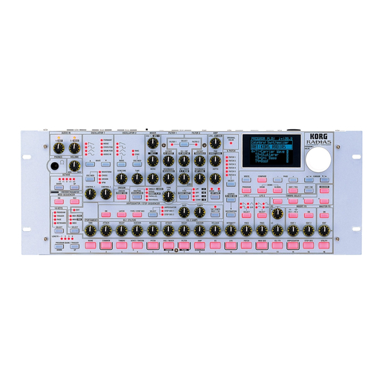
Page 16: Front And Rear Panels
Front and rear panels Front panel The parameters printed in white characters on a dark background are vocoder parameters. 1. AUDIO IN 5. OSCILLATOR 1 [1/INST] knob WAVE [▲][▼] buttons This knob adjusts the input level from the INPUT 1 jack. These select the waveform for oscillator 1. - Page 17 Front panel 7. UNISON FRMNT SHIFT: When editing vocoder settings, this ad- justs the amount of formant shift. [UNISON - FRMNT REC] button UNISON: Switches the unison function on/off. 11. FILTER COMMON FRMNT REC: When editing vocoder settings, this records format motion data for use with the Formant [SELECT] button Motion function.
- Page 18 Front and rear panels [PROGRAM] button tion source that will be applied to the cutoff frequency of the synthesis filter. Press this button to enter the Program Play mode. [DESTINATION] button [DRUM] button Selects the modulate-able parameter that the selected Press this button to enter the Drum Play mode.
- Page 19 Front panel [LO] knob button to enter record-ready mode; recording will begin when you play the keyboard etc. Adjusts the level of the low frequency range. Turning this toward the right will boost the level of the low fre- [SELECT] button quency range, and turning it toward the left will de- Selects the arpeggiator or the step sequencer that will be crease the level of the low frequency range.
-
Page 20: Rear Panel
Front and rear panels [SELECT] button If you select PAGE, the sixteen keys will select editing pages or global mode pages. In addition to selecting the function of the 16 knobs If you select KEYBOARD, keys [1]–[16] will function as above the 16 panel keys, this button also selects which a simple polyphonic MIDI keyboard, and will play the Mod Sequencer is available for editing. - Page 21 Rear panel Use the DYNAMIC MIC setting if you’re connecting a mic to the INPUT 2 jack. Use the LINE setting if you’re connecting a line-level de- vice such as a synthesizer or audio device to the INPUT 2 jack. Use the CONDENSER MIC setting if you’re connecting the headset mic that came with the RADIAS to the CONDENSER MIC jack.
-
Page 22: Setup
ASSIGNABLE SWITCH jack This jack is used for a switch type of pedal such as the Korg PS-1 pedal switch or Korg DS-1H damper pedal. The foot switch can be used for various functions including switching programs, changing octaves, or turn- ing portamento or the arpeggiator on/off. -
Page 23: Connecting External Midi Equipment
Setup Specify the pedal polarity in the Global mode P08: PEDAL & SW page. ☞p.119 “P08–1: PEDAL/SW” ☞p.119 “A.SwFunc (Assignable Switch Function)” 4. Connecting external MIDI equipment The RADIAS can be used as a multitimbral MIDI sound module, or as a controller for other MIDI equip- ment. -
Page 24: Connecting Your Computer
Setup 5. Connecting the audio inputs – INPUT jacks You can connect any audio source (synthesizer, CD player, etc.) to the INPUT jacks. Via this connection, the audio coming from this external source can be processed in the same way as the RADIAS’ internal sound generator, or used as the carrier or modulator for the vocoder. -
Page 25: Quick Start
During playback, the display will show the song name. You can press the cursor buttons to switch demo songs during playback. Press the [EXIT] button to stop demo playback and return to the Program Play mode. All Demo Songs: © 2005 KORG Inc. — all rights reserved. -
Page 26: Selecting And Playing A Program
Quick Start Playing programs – Program Play mode The RADIAS contains a total of 256 programs, organized into sixteen banks (A–P) with sixteen programs in each bank. Here’s how to select and play different programs. Entering the Program Play mode The RADIAS defaults to the Program Play mode each time the power is turned on. -
Page 27: Playing Programs - Program Play Mode
Playing programs – Program Play mode Using the [PROGRAM/VALUE] dial You can use the [PROGRAM/VALUE] dial to select programs. Turn the dial toward the right to step through the programs in ascending order, or toward the left in descending order. Selecting programs by category Each program can be assigned to a category. -
Page 28: Arpeggiator
Quick Start Play the RADIAS using the 16KEYS [1]–[16] keys. The current program will play. The 16KEYS [1]–[16] keys are assigned to the following pitches. Changing the octave You can change the range of the 16KEYS [1]–[16] keys by octaves, with a maxi- mum range of a maximum of two octaves up or two octaves down. - Page 29 Arpeggiator Hold down a chord on the keyboard. You will hear the arpeggio pattern. Turn the Latch function on. Press the [LATCH] button. When Latch is on, the latch button will light. With the Latch on, the arpeggio will continue playing even after you remove your hand from the keyboard.
-
Page 30: Step Sequencer
Quick Start Step Sequencer You can use the two step sequencers to record and play back a phrase or pattern. This section explains how to play a step sequence and make some simple edits. For details on recording and editing, refer to p.50 “Step sequencer recording and editing.” Playing a program using the step sequencer Some of the factory programs already contain sequence data. -
Page 31: Modulation Sequencer
Modulation Sequencer Modulation Sequencer The modulation sequencer applies time-varying change to sound parameters in a way similar to an analog sequencer. When the sound is played, it will change over time according to the values stored for each of the sixteen steps. -
Page 32: Audio In
Quick Start Audio In You can use the RADIAS’ filters, amp, and effects to process an external audio source in the same way as an internal oscillator waveform. The following section describes how to connect a CD player or an MD player and modify the incoming audio. -
Page 33: Vocoder
Vocoder Vocoder Here’s how to select one of the RADIAS’ vocoder programs and try out some of the vocoder function. On the front panel, functions labeled in white characters on a dark background are vocoder param- eters. Playing a vocoder program Before you connect a mic, set the AUDIO IN [2/VOICE] knob to the 0 position. -
Page 34: Playing A Drum Kit - Drum Play Mode
Quick Start Playing a Drum Kit – Drum Play mode The RADIAS provides thirty-two drum kits, each consisting of sixteen drum instruments. You can assign these instruments to note numbers and play them from the keyboard, and one timbre in each program can be assigned a drum kit. -
Page 35: Editing
Editing A program consists of a large number of parameters; the names and synth parameters of all four timbres, the program common settings such as program name, vocoder settings etc. If you want to create a program “from scratch,” you’ll need to understand what each of these parameters does. An easier way to get started is to start by choosing one of the factory programs or timbre templates and editing the parameters to under- stand what they do. - Page 36 Editing Selecting the timbre to edit If the program consists of more than one timbre, here’s how to select the timbre you want to edit. Use the TIMBRE SELECT [1]–[4] buttons to select the timbre you want to edit. The button for the selected timbre will blink. The front panel knobs and buttons and the timbre param- eters shown in the display will apply to the timbre that is selected.
-
Page 37: Changing A Value
Basic editing procedure Selecting and editing a parameter Use the cursor buttons to select the parameter you want to edit. When you press one of the cursor button, the cursor will move to the next parameter, and it will be high- lighted in the display. -
Page 38: Compare Function
Editing Compare function While editing a program, you can compare the edits you have made to the original program or timbre. Press the [COMPARE] button. The display will indicate “Compare.” Play the keyboard to hear the sound as it was before you began editing it. -
Page 39: Loading Other Timbre Sounds/The Template Function
Basic editing procedure Loading other timbre sounds/The Template function The Template function can be a real convenience when you’re creating a program sound or an effect. You can load a program template that is close to the type of sound you have in mind, and then edit it to create a program much more easily than working from scratch. -
Page 40: Assigning A Name
Editing Making a template Here’s how to make a timbre template. Templates you make can be loaded in the same way as the factory templates. You will use the P16: UTILITY page to make templates. (☞p.107 “P16 UTILITY,” p.113 “P16 UTILITY”) Select a program that uses a timbre you want to store as a template, and enter the Program Edit mode. - Page 41 Basic editing procedure To enter a drum instrument name, use the Drum Edit mode’s P01: NAME page (☞p.111 “P01–2: INST (Drum Instrument Name)”). • Templates Template names are displayed when you are loading templates. You can enter a template name when creating a template in the P16: UTILITY page of the mode in which you’re creating the template (☞p.107 “P16 UTILITY,”...
- Page 42 Editing Assigning a category When you specify a program name, you can also assign that program to a category. If you assign an appro- priate category to each program, you’ll be able to find programs more efficiently (☞p.21 “Selecting pro- grams by category”).
-
Page 43: Program Parameter Editing
Program parameter editing Program parameter editing Synth parameter editing This section explains how to edit the synthesis parameters that make up an individual timbre. The following section assumes that you have started by pressing the front panel TIMBRE SELECT [1] button to select timbre 1 as the object of editing, and that you are in the Program Edit mode. -
Page 44: Filter Settings
Editing Oscillator 2 settings Use the OSCILLATOR 2 [WAVE] button to select the waveform of oscillator 2. The waveform will change each time you press the button, and the LED of the selected waveform will light. You can choose one of four different waveforms. - Page 45 Program parameter editing Use the FILTER 1 [CUTOFF] knob to adjust the cutoff frequency of filter 1. Turning the knob toward the right (increasing the value) will make the sound brighter. Use the FILTER 1 [RESONANCE] knob to adjust the resonance of filter 1. Turning the knob toward the right (increasing the value) will boost the region near the cutoff fre- quency.
- Page 46 Editing Creating time-varying change in the tone (EG1) EG1 applies time-varying change to the cutoff frequency (the “Cutoff” of FILTER 1 or FILTER 2). EG1 applies the same effect to filter 1 and filter 2. You can edit the virtual patching so that EG1 will apply modulation to other parameters as well. Note off Note on Time...
- Page 47 Program parameter editing Timbre output settings Timbre output settings Use the AMP [LEVEL] knob to adjust the volume of the timbre. Use the AMP [PAN] knob to adjust the panning (position in the stereo field) of the timbre. If this knob is in the center position (CNT), the sound will be sent equally from the left and right outputs (center).
-
Page 48: Lfo Settings
Editing Use the EG 2 [SUSTAIN] knob to set the sustained volume level. Turn the knob toward the right (increase the value) to make the sustain volume louder. Use the EG 2 [RELEASE] knob to adjust the time required for the volume to fade away after you release the key. - Page 49 Program parameter editing Applying modulation to various parameters – Virtual Patch (V.PATCH) Virtual Patch lets you assign fifteen different modulation sources to modulate various sound parameters. If you want to use the front panel knobs to adjust the virtual patch parameters, use the MOD SE- QUENCER [SELECT] button to make the EDIT indicator light.
- Page 50 Editing SEQ COMMON parameter settings Before you create the sequence data, use the SEQ COMMON parameters to specify the number of steps in the sequence, and how the data will play back. Go to the Program Edit mode P12–1: MOD SEQ – COMN tab page.
- Page 51 Program parameter editing You can use the above procedure to edit existing sequence data or to edit sequence data you record- ed in realtime. Recording modulation sequence data in realtime – the Motion Rec function The Motion Rec function lets you tweak a knob in realtime, record the movements of that knob, and apply those changes to the steps in a modulation sequencer.
-
Page 52: Editing The Effect Parameters
Editing Editing the effect parameters The RADIAS provides a two-band equalizer and two insert effects for each timbre, and one master effect for each program. Here’s how to edit the insert effect and master effect settings. If you want to use the front panel knobs to edit the sequencer, insert effect, and master effect pa- rameters, make sure that the MOD SEQUENCER [SELECT] button is set to EDIT. -
Page 53: Editing The Arpeggiator
Program parameter editing Go to the Program Edit mode P13–4: EQ/FX – MFX tab page. Move the cursor to the effect name, and select effect type. Use “Edit” to select the effect parameter that will be adjusted by the MASTER FX [EDIT] knob. The available parameters will depend on the effect type. - Page 54 Editing Use “ScanBotom” and “ScanTop” to specify a “key window” - the region of notes on the key- board that will trigger the arpeggiator. The arpeggiator will operate when you play keys in the region between “ScanBotom” and “ScanTop.” Editing each step played by the arpeggio pattern (ARPEGGIATOR – TRIGGER) You can specify the note played by each step of the arpeggio pattern.
- Page 55 Program parameter editing Using the cursor buttons and the [PROGRAM/VALUE] dial to edit the note status Go to the P14–2: ARPEGGIATOR – TRIG tab page. Use the cursor buttons to move to the step you want to edit. You can hold down a cursor button to move rapidly. Use the [PROGRAM/VALUE] dial to turn each note on/off.
-
Page 56: Step Sequencer Recording And Editing
Editing Step sequencer recording and editing You can use the step sequencers to record and play back phrase patterns or drum patterns. This section ex- plains how to record using the step sequencer, and how to edit the patterns you record. For details on playback, refer to p.24 “Playing a program using the step sequencer.”... - Page 57 Program parameter editing Use “Transpose” to specify whether the pitch you play on the keyboard will control the pitch of the notes generated by the step sequencer. For this example, turn this On. When this is on, the pitch of the phrase or pattern generated by the step sequencer will change according to the “BaseNote”...
- Page 58 Editing If you use the 16KEYS [SELECT] button to select TRIGGER, the 16KEYS [1]–[16] keys will blink to indicate the step you are currently entering. You can press one of the [1]–[16] keys to select the step you want to enter. To select step 17 or later, use the 16KEYS PROGRAM BANK/TRIGGER [UP] button to make the LENGTH LED light for the steps you want to select.
- Page 59 Program parameter editing press this key repeatedly, the note data for the notes you are holding down will be entered for the corresponding steps. Press the [TYPE/STEP REC] button or the [EXIT/NO] button to stop recording. In this example we’ve stopped recording at step 5, so the “Last Step” of step sequencer 1 will auto- matically be set to 4.
- Page 60 Editing Using the 16KEYS [1]–[16] keys to edit the notes (Drum Pattern editing) Using the 16KEYS [1]–[16] keys to edit is the appropriate method when you’ve assigned a drum kit and you want to edit the rhythm pattern for each drum instrument. In this case, the note (pitch) shown by the 16KEYS [1]–[16] keys for each step will be the note specified by the Program Edit mode P15–2: STEP SEQ –...
- Page 61 Program parameter editing Use “Trigger” to select whether the notes at that step will play. specifies that the notes at that step will play. – specifies that the notes at that step will not play. If you change a – step to , the note numbers previ- ously assigned to that step will be assigned.
-
Page 62: Vocoder Editing
Editing Vocoder editing When the TIMBRE SELECT [VOCODER] button is dark, the vocoder is off. Pressing this button will turn the vocoder on, and the button will be lit. You can use one timbre as the carrier, and apply a vocoder effect to it. To edit the vocoder settings, press the TIMBRE SELECT [VOCODER] button and then press the [EDIT] but- ton. - Page 63 Program parameter editing Use “Threshold” to prevent noise during periods when there is no singing or speaking being captured by the mic. Higher settings will make it easier for the audio to be cut. Adjust this so that the noise is not obtru- sive when you’re not speaking into the mic.
- Page 64 Editing Formant Motion function The Formant Motion function plays the vocoder using vocal or other sound data that you recorded ahead of time and saved in the RADIAS. This lets you play the vocoder without having to speak into the mic. Assigning a formant motion to the modulator Here’s how to play the vocoder using factory preloaded formant motion data.
- Page 65 Program parameter editing If you want to keep the formant motion data you recorded, execute the Write operation. The formant motion data you’re editing will be lost if you select other formant motion data, change programs, or turn the RADIAS’ power off (STANDBY) without writing, or if you receive a MIDI data dump for this data from a connected external device.
-
Page 66: Drum Parameter Editing
Editing Drum parameter editing What is a drum kit? A drum kit is a set of sixteen individual sounds such as bass drum or cymbal, each assigned to a different note of the keyboard. The RADIAS contains thirty-two of these drum kits. What is a drum instrument? Each of the sounds (e.g., bass drum or cymbal) making up a drum kit is called a “drum instrument.”... - Page 67 Drum parameter editing 5. Saving a drum kit and drum instruments – WRITE If you turn off the power or switch to a different drum kit without Writing an edited drum kit or drum in- strument, your changes will be lost. If you want to save the edited drum kit or drum instrument, you must execute the Write operation.
- Page 68 Editing Copying a drum instrument from another drum kit If you want to create a drum sound that’s similar to a drum instrument in another existing drum kit, you can copy that drum instrument. In the Drum Play mode, select the copy-source drum kit and drum instrument. Press the [EDIT/YES] button to enter the Drum Edit mode.
- Page 69 Drum parameter editing Assigning a drum kit to a timbre of a program Here’s how to assign a drum kit you created to one of the timbres in a program. This allows you to play the drum kit in the Program Play mode, or use a step sequencer to play a rhythm pattern while you play other sounds manually.
-
Page 70: Key Zone Settings
Editing Key Zone settings Layers and splits The region of keys in which a timbre will sound is called the “key zone.” By specifying the key zone for each timbre you can create a program in which different sounds are heard from different zones of the keyboard. By making key zone settings for each timbre, you can create layered or split sounds. - Page 71 Key Zone settings In the P03–1: TIMBRE – TMBR tab page, use the “Select” field of timbre 1 to select a bass-type sound. Use the “Select” field of timbre 2 to select an electric- piano sound. Use the “Select” field of timbre 3 to select a strings- type sound.
- Page 72 Editing Selecting a drum kit for timbre 4 Go to the Program Edit mode P03–1: TIMBRE – TMBE tab page, and use the “ON” setting to turn timbre 4 On. Press the front panel TIMBRE SELECT [4] button to select timbre 4. Go to the P02–2: COMMON –...
-
Page 73: Envelope Follower Settings
Envelope Follower settings Envelope Follower settings By using the envelope follower you can use the varying level of an external audio signal to modulate a vari- ety of parameters such as the filter cutoff. In the following example, we’ll explain how you can set up the envelope follower to modulate the Filter1 Cutoff of timbre 1 using the audio signal from a rhythm pattern (or other source) connected to the INPUT jack. -
Page 74: Global Parameter Editing
Editing Global parameter editing In the Global mode you can make settings that apply to the entire RADIAS and edit user scales. Basic editing procedure 1. To enter the Global mode Press the [GLOBAL] button. You will enter the Global mode. The top line of the dis- play will indicate the page number and page name, and the middle area of the display will show parameter names and values. -
Page 75: Editing Parameters
Global parameter editing Global data includes the formant data (☞p.58 “Formant Motion function”), but this data cannot be saved in the Global mode. You must save it in the Program Play mode, the Program Edit mode, or the Vocoder Edit mode. (☞p.59 “Writing formant motion data”) Editing parameters Disabling memory protect The RADIAS provides a memory protect setting that prevents data from being rewritten inadvertently. -
Page 76: Synchronizing With An External Midi Device
Editing Setting the MIDI channel to match an external device If you’re using the RADIAS as a MIDI sound module or as a master keyboard, you must set the RADIAS’ global MIDI channel to match the MIDI channel of your external MIDI device. For details on this setting, refer to p.17 “MIDI channel settings –... - Page 77 Global parameter editing Press the [EXIT/NO] button. You will return to the screen of step 1. Do not operate the RADIAS’ knobs, buttons, keyboard, or wheels etc. while data is being transmit- ted. In order to receive a data dump into the RADIAS, you must first turn the Global mode P02: MEM- ORY page “Protect”...
- Page 78 Editing...
-
Page 79: Parameter
Parameter Program parameters Drum parameters Global parameters Effect guide... -
Page 80: Program Parameters
Program parameters Program parameters are the individual parameters that P01–2: TIMBRE (Timbre Name) together determine the sound of a program. Here you can specify the name of the timbre selected by If you want to keep the edits you’ve made to a pro- the front panel TIMBRE SELECT [1]–[4] buttons. - Page 81 2. Program Common Link The vocoder is off, and will not be used in the current The front panel controls will edit the timbre selected by program. the [TIMBRE SELECT] button. Normally you will choose this setting. Timbre1…Timbre4 The vocoder is on, and will be used by the current pro- gram.
- Page 82 Program parameters For example, suppose that you have a drum kit that as- P02–2: DRUM (Drum Common) signs the sixteen drum instruments Kick–Hand Clap to the notes C4 through D#5, as shown in the illustration. These are the parameters used with a drum kit. Setting “NoteShift”...
-
Page 83: P03 Timbre
2. Program Common 1: Source [Off, ExtIn1, ExtIn2, ExtIn1+2, IntBus] 000…127 A note-on will be sent when the level of the detected en- Selects the input source for the envelope follower. velope exceeds the value you specify here. If this is set to 0, a note-on will be sent regardless of the This turns the envelope detecting function off. - Page 84 Program parameters 2: IndOut (Individual Output) [IndL/R, IntBus] The timbre will be on, and can be played by the key- Specifies the destination of the INDIV. L and R bus. board or by note-on messages from the MIDI IN connec- Use “OutBal”...
- Page 85 2. Program Common 1: Ch (MIDI Channel) [01…16, GLB] P03–5: CC-A (Controller’s CC) Specifies the MIDI transmit/receive channel. These settings specify whether MIDI control change By setting two or more timbres to the same MIDI chan- messages such as Modulation Wheel and Damper Pedal nel and using the P03–3: TIMBRE –...
-
Page 86: Synth Parameters
Program parameters 3. Synth Parameters Multi The EG will be retriggered each time a new key is pressed. These are the synthesis parameters that are used to cre- ate a timbre. Note on Note on Each of the four timbres has the same pages. Use the TIMBRE SELECT [1]–[4] buttons to select the timbre you Trigger want to edit. -
Page 87: P05 Pitch
3. Synth Parameters 4: VibratInt (Vibrato Intensity) This parameter is available if the unison “Sw” function is On. [–2400…+2400cent] Specifies the depth of the vibrato that will occur when The “Detune” setting has no effect for OSC1 (oscil- the modulation wheel is moved to its maximum posi- lator 1) if the P06–1: OSC1 “Wave (OSC1 Wave)”... - Page 88 Program parameters 1: Wave (OSC1 Wave) WAVE [π], [†] Control2: Harmonics (VPM Harmonics) [01…32] [Saw…AudioIn] Specifies the frequency of the VPM modulator as a multiple (harmonic) of the oscillator 1 fundamental. Selects the waveform of oscillator 1 (OSC 1). The parameters controlled by the “Control1”...
- Page 89 3. Synth Parameters Control2: Wave Sel (Wave Select) [01…64] Sine wave is a mild tone that contains only the funda- Selects the PCM waveform. mental frequency with no overtones. DrumPCM When “OSC Mod” = Waveform This provides various PCM waveforms such as drum and percussion sounds.
- Page 90 Program parameters In order to use the internal bus, you must make Unison Detune settings in the P03–2: TIMBRE – OUT tab page to OSC1–1 assign the timbre output to the internal bus. 3: OSC Mod OSC MOD OSC1–2 [Waveform, Cross, Unison, VPM] Selects the modulation type for oscillator 1.
- Page 91 3. Synth Parameters When “OSC Mod” = VPM Ring This type of modulation generates frequencies at the Control1: Mod Depth (VPM Depth) [000…127] sum and difference of oscillators 1 and 2. You can adjust Adjusts the depth of VPM. “Semitone” and “Tune” to create metallic sounds with Control2: Harmonics (Mod Harmonics) [01…32] little sense of pitch.
-
Page 92: P07 Filter
Program parameters Para P06–3: MIXER Filter 1 and filter 2 are connected in parallel. These parameters specify the output level of each oscil- OSC1 lator. The settings you make here will determine the in- put level to the filter. Filter1 OSC2 Filter2 Noise... - Page 93 3. Synth Parameters Increasingly negative (–) values will produce a greater HPF (High Pass Filter) effect in the opposite direction. Cutoff Int=–63 Cutoff frequency Int=–32 Int=0 specified by Frequency “Cutoff” Cutoff Note off Note off Note on Note on Time THRU The sound will output directly, without passing 6: KeyTrack (Keyboard Track) ...
-
Page 94: P08 Amp (Amplifier)
Program parameters 2: FiltType (Filter2 Type) TYPE 2: Pan PAN [L63…CNT…R63] [LPF, HPF, BPF, COMB] Adjusts the panning (stereo position) of the timbre. Selects the filter type. If a drum kit is assigned to the timbre, the param- eter adjusted by the front panel [PAN] knob will This setting will affect the maximum number of be the P02–2: COMMON –... -
Page 95: P09 Eg (Envelope Generator)
3. Synth Parameters This may produce high output volumes than other Depth: 000 Depth: 064 Depth: 127 wave shape types. 7: PunchLvl (Punch Level) [000…127] Creates a more “snappy” attack by adjusting the amount of pulse waveform that is added to the oscillator OctSaw output only during the attack. -
Page 96: P10 Lfo
Program parameters 1: Attack ATTACK [000…127] Positive (+) values EG times will become longer when you play softly, and Specifies the time from note-on until the attack level (the will become shorter when you play strongly. maximum value of the envelope) is reached. Negative (–) values 2: Decay ... -
Page 97: P11 Patch (Virtual Patch)
3. Synth Parameters S&H Squ+ Note on Note on Shape = –63 Note all off Shape = 0 Voice The phase of the LFO will be reset for each individual note-on, and each voice will be modulated at an inde- pendent phase. -
Page 98: P12 Mod Seq (Modulation Sequencer)
Program parameters Velocity AmpLevel Keyboard velocity (playing dynamics) will be the mod- The P08–1: AMP page “Level” parameter will be modu- ulation source. lated. P.Bend Pitch bend will be the modulation source. The P08–1: AMP page “Pan” parameter will be modulat- M.Wheel LFO1Freq Modulation wheel will be the modulation source. - Page 99 3. Synth Parameters Reverse If both the modulation sequencer and the arpeg- Play from the last step (the step number specified by giator are on, you should set this parameter to Off “Last Step”) in reverse. or Timbre. If this is set to Voice, the sequence will be reset each time the arpeggiator generates a Reverse (Last Step=16) note.
-
Page 100: P13 Eq/Fx (Equalizer/Effect)
Program parameters P13 EQ/FX (Equalizer/Effect) If you set “Knob” to OSC1c2 (OSC1 Control 2) when OSC1 “Wave” is set to Synth PCM or Drum PCM, the operation will be the same as Step even Here you can edit the parameters for the equalizer and if this parameter is set to Smooth. - Page 101 3. Synth Parameters The settings in this page are common to all tim- bres, regardless of the timbre that is selected by the front panel TIMBRE SELECT [1]–[4] buttons. The master effect is not applied to the Ind Out out- puts.
-
Page 102: Arpeggiator
Program parameters 4. ARPEGGIATOR STEP SEQ1 Step sequencer 1 will be assigned to the timbre. When you start the step sequencer by triggering it from These are the arpeggiator-related parameters. the keyboard etc., the timbre will be played by the spec- ified sequence pattern. - Page 103 4. ARPEGGIATOR The “Tempo” setting will also be the playback tempo for the modulation sequencer and step se- quencer. 2: KeySync [Off, On] Specifies whether the arpeggiator and step sequencer If you hold down more than the number of keys will be synchronized with the keyboard.
- Page 104 Program parameters P14–2: TRIG (Arpeggiator Step On/Off) Here you can turn individual steps of the arpeggio pat- tern on/off. This is a way to add rhythmic variety to an arpeggio pattern. You can use the P16–5: UTILITY – ARP tab page “CopyArpStep”...
-
Page 105: Step Sequencer
5. Step Sequencer 5. Step Sequencer TEMPO Specifies the playback tempo of the step sequencer. Higher settings will make the tempo faster. You can set These are the parameters for the step sequencers. this using the P14–1: ARPEGGIATOR – COMN tab page The RADIAS provides two step sequencers. - Page 106 Program parameters Loop 7: Swing [–100…+100 %] The recorded sequence data will play as a loop as long Adjusts the timing of the even-numbered notes in the as you hold down a note. step sequencer playback. Step When the Resolution is 1/8 Each time you press a note, only one step of the recorded sequence data will play and then advance to the next step.
- Page 107 5. Step Sequencer Notes within the same step will all have the same Note status gate time regardless of their note number. will sound – : will not sound 3: Velocity [001…127, KEY] Specifies the velocity for the note(s) sounded by each step.
- Page 108 Program parameters 1: LastStep [01…32] 2: RunMode [OneShot…Step] 3: Transpose [Off, On] 4: BaseNote [C-1…G9] 5: GateTime (Gate Time Offset) GATE [–100…+100] 6: Resolutn (Resolution) [ 1/32… 1/1] 7: Swing [–100…+100 %] 8: ScanBotom (Scan Bottom) [C-1…G9] 9: ScanTop (Scan Top) [C-1…G9] These are the same as the parameters of step sequencer ☞p.99 “P15–1: COMN (STEP SEQ1 Common)”...
- Page 109 5. Step Sequencer MIDI channels that drive the arpeggia- Global MIDI Ch: 1 tor and step sequencers Timbre 1 MIDI Ch=GLB The arpeggiator and step sequencers are driven by both Timbre 2 ARPEGGIATOR SELECT=Timbre 2 the global MIDI channel and by the MIDI channel of the MIDI Ch=2ch Trigger MIDI Ch= 2ch...
-
Page 110: Vocoder Parameters
Program parameters 6. Vocoder Parameters If you’re using the internal bus as an input source, you must first use the Program Edit mode P03–2: TIMBRE – OUT tab page to assign the timbre out- These are the vocoder-related parameters. put to the internal bus. (☞p.78 “P03–2: OUT (Tim- To edit the vocoder parameters used in a program, press bre Output)”) the TIMBRE SELECT [VOCODER] button and then the... -
Page 111: P07 Filter
6. Vocoder Parameters P07 FILTER 4: FcModSrc (Fc Modulation Source) FC MOD SRC [EG1…MIDI5] Here you can edit the parameters for all the band pass Selects the modulation source that will be applied to filters of the carrier, and the envelope follower of the “FcOffset.”... - Page 112 Program parameters Audio If you want to use the internal bus as the input The input source selected by “AudioSrc” will be the source, you must first use the Program Edit mode modulator. P03–2: TIMBRE – OUT tab page to assign the tim- bre output to the internal bus.
-
Page 113: Utility
7. Utility 9: DirectLvl (Direct Level) DIRECT LEVEL CopyVOCODER [000…127] Copies the vocoder settings from another program to the vocoder settings of the selected program. Sets the volume level at which the modulator input source will be output directly (unaffected). 7. - Page 114 Program parameters SwapTIMBRE NameTemplate Exchanges the settings of the timbre selected by “TIM- Edits the name of a template. BRE SELECT” with the settings of a different timbre used in the same program. Use “Edit” to select NameTemplate. Use “Dest” to select the template number (001– Use “Edit”...
- Page 115 7. Utility SwapModSeq If you select ALL and then execute the Initialize function, the P12–1: MOD SEQ – COMN tab page Exchanges a modulation sequence of the currently se- parameters and the three modulation sequencers lected program or timbre with a modulation sequence of will be initialized.
- Page 116 Program parameters MakeMFxTemp SwapStepSeq Creates a template using master effect settings of the Exchanges the step sequence 1 and step sequence 2 of currently selected program. the currently selected program. Use “Edit” to select MakeMFxTemp, use “Source” to se- Use “Edit” to select SwapStepSeq. lect the master effect, use “Dest”...
-
Page 117: Drum Parameters
Drum parameters 2. Drum Common These are the parameters for drum kits and drum instru- ments. To edit these parameters, press the [DRUM] button and then press the [EDIT] button. P02 COMMON 1. Name P02–1: DRUM MAP Here you can create a drum kit by assigning drum in- struments to separate notes of the keyboard. -
Page 118: Drum Inst
Drum parameters 3. Drum Inst P07 FILTER Here you can set drum instrument parameters. P07–1, 2: FILTER1, 2 The contents of the parameters are the same as for the timbre parameters. For details, refer to p.74 “Program parameters.” To select the drum instrument you want to edit, set 16KEYS [SELECT] to PROGRAM, and use the [1]–[16] keys to select a drum instrument. -
Page 119: P10 Lfo
4. Utility P10 LFO Use “Edit” to select Init Kit, change “Sure?” to “Press [YES],” and then press the [EDIT/YES] button. (☞p.107 “InitPROG”) Init Inst P10–1, 2: LFO1, 2 Initializes the currently selected drum instrument. Use “Edit” to select Init Inst, change “Sure?” to “Press [YES],”... -
Page 120: Global Parameters
Global parameters These are the parameters that affect the entire RADIAS. With the PostKBD setting, when both the arpeg- To access the Global parameters, press the [GLOBAL] giator and the sequencer are turned on, and MIDI button. data played on the keyboard (or the SELECT [1]– If you want to keep the changes you made, you must ex- [16] keys) is recorded on an external sequencer ecute the Write operation. -
Page 121: P02 Memory
4. Utility Catch 8: This curve produces a fairly steady effect with When you turn the knob, the parameter value will not little change for medium-strength playing (a change until the knob position matches the stored value. flatter curve than 7). We recommend that you use this setting when you don’t want the sound to change abruptly, such as during a live Curves 7 and 8 produce little change for medium-... -
Page 122: P03 Preload
Global parameters P03 PRELOAD P04 MIDI P03–1: PRELOAD P04–1: MIDI Here you can load the factory-set data. For details on the loading procedure, refer to p.69 “Re- storing the factory settings.” 1: MIDI Ch [01…16] Sets the global MIDI channel. The global MIDI channel is used for the following oper- 1: Load data [All Data…GLOBAL]... -
Page 123: P05 Midi Dump
4. Utility Ext-MIDI RADIAS PC USB-MIDI Port The RADIAS will operate as a slave (the controlled de- RADIAS MIDI OUT USB MIDI RX (EXT) vice) to MIDI clock messages received from the MIDI IN RADIAS KBD/KNOB USB MIDI TX (INT) MIDI OUT connector. -
Page 124: P06 Midi Filter
Global parameters 2: BANK Chg (Bank Change) [x, o] Also, you must never turn off the power of the RADIAS’ during this time. Specifies whether bank change messages will be trans- mitted and received. MIDI dumps and MIDI dump requests from a con- x (Disable) nected external MIDI device will not be received Bank change messages will not be transmitted or re-... -
Page 125: P08 Pedal/Sw
Specifies the polarity of the pedal switch connected to the ASSIGNABLE SWITCH jack. With the factory set- tings this is set to – (KORG). Choose the – setting if you’re using a Korg PS-1 pedal switch, or if you’re not using any pedal 1: A.Pedal (Assignable Pedal) [Volume…FootPedal] switch. -
Page 126: P09 User Scale
Global parameters P09 USER SCALE 1: Category [01…16] Select the number of the category whose name you want to edit. P09–1: USER SCALE 2: Name [!…’] Here you can create a user scale. You can adjust the pitch Enter a name for the category. of each note in the octave (C…B) in a range of –99–+99 The available characters and the procedure are the same cents. -
Page 127: Effect Guide
Effect guide Overview About the delay time The effect section of the RADIAS consists of a two-band TimeRatio EQ and two insert effects per timbre, and one master ef- fect for the entire program. You can use the EQ and in- For delay effects, the actual delay time is determined by sert effects to create the sound of each timbre, and use multiplying the delay time with the “TimeRatio.”... -
Page 128: Controlling The Effect Parameters
Effect guide Delay time for the insert effects Broadly speaking, there are two types of effect for which you can specify a delay time. • Delay effects • Modulation effects such as chorus that internally use a fixed delay time If you use such an effect in the two insert effects, the de- lay time of the effects can be set for a maximum of 1.0 seconds for each timbre. -
Page 129: Effect Parameters
Effect parameters Effect parameters Attack [0000.1…0500.0ms] only MFX • [parameter name] : This parameter will be Sets the attack level. displayed and can be set only when the effect is used by a master effect. Compressor - Attack Level only IFX •... - Page 130 Effect guide Attack [0000.1…0500.0ms] Gate - Threshold Sets the attack time. A higher attack time will cause the Output Level compression to be applied more slowly. Threshold Limiter - Attack Threshold Louder Input Level Gate - Attack / Release Threshold Ratio=Inf : 1 Attack=1 Attack=0.1ms...
- Page 131 Effect parameters Mod Src (Mod Source) [LFO, Ctrl] LFO Wave (LFO Waveform) [Saw, Squ, Tri, Sin, S&H] Selects the modulation source that will control the cutoff Selects the LFO waveform. This parameter will be dis- frequency. played and can be set if “Mod Src” is LFO. If you set this to LFO, the LFO will modulate the cutoff frequency.
- Page 132 Effect guide Response (Modulation Response) [000…127] Source Explanation Adjusts the response of the modulation effect. A setting F.Pedal Foot pedal of 0 produces the slowest response. F.SW Foot switch Damper Damper pedal Env Sens (Envelope Sensitivity) [000…127] Envelope follower When “Mod Src” is set to Auto, sets the sensitivity of auto-wah.
- Page 133 Effect parameters Ctrl Src (Control Source) [Off, Velocity…MIDI5] B1 Freq (B1 Frequency) [20Hz…20.0kHz] Selects the control source used when “Mod Src” is set to Sets the center frequency of Band 1. Ctrl. The selected source will control the center frequen- B1 Q [00.5…10.0] cy of the wah.
- Page 134 Effect guide 7. Distortion 8. CabinetSimltr (Cabinet Simulator) This is a distortion effect with a three band EQ, giving This simulates the acoustical character of a guitar amp’s you a broad range of variations. speaker cabinet. Wet: Mono In - Mono Out / Dry: Stereo In - Stereo Out Wet: Mono In - Mono Out / Dry: Stereo In - Stereo Out Left Left...
- Page 135 Effect parameters 9. TubePreAmpSim (IFX)/ Tu1 Satu (Tube1 Satulation) [000…100%] Sets the input/output response for stage 1. With higher St.TubePreAmp (MFX) settings of this value, the waveform will change at high gain levels, tending to cause distortion. Lower settings This effect simulates a two-stage vacuum tube preamp. of this value will produce linear response.
- Page 136 Effect guide 10. St.Decimator (Stereo Decimator) Sync Note (LFO Sync Note) [8/1…1/64] Sets the LFO frequency as a proportion of the tempo set This effect creates a rough sound like a cheap sampler by the [TEMPO] knob. This parameter will be displayed by lowering the sampling frequency and data bit length.
- Page 137 Effect parameters only MFX 12. Early Reflect (Early Reflections) SmthHall Hall-type reverb, producing the reverberation of a larg- This effect is only the early reflection part of a reverber- er hall or stadium. The reverberation features a smooth ation sound, and adds presence to the sound. You can release.
- Page 138 Effect guide 13. L/C/R Delay Low Damp [000…100%] Sets the damping amount in the low range. This multitap delay outputs three Tap signals to the left, center, and right respectively. You can also adjust the Trim [000…127] left and right spread of the delay sound. Sets the input level.
-
Page 139: Auto Panning Delay
Effect parameters TempoSync (LFO Tempo Sync) [Off, On] The amount of feedback for the right channel is linked with the proportion of the left and right delay times so Specifies whether the LFO cycle will be synchronized that the decay times of the left and right channels will with the tempo specified by the [TEMPO] knob or MIDI stay the same. - Page 140 Effect guide 16. St.AutoPanDly Key Sync (LFO KeySync) [Off, Timbre] Specifies whether the LFO will be reset by note-on. (Stereo Auto Panning Delay) p.125 “Key Sync (LFO KeySync)” This is a stereo delay that uses an LFO to pan the delay sound between left and right.
-
Page 141: Tape Echo
Effect parameters 19. Tape Echo LFO Freq (LFO Frequency) [0.01…100.0Hz] Sets the LFO speed. Increasing this value will result in a This effect simulates a tape echo unit. The distortion and faster frequency. tonal change typical of magnetic tape are also repro- duced. - Page 142 Effect guide 21. Ensemble Spread [000…127] Sets the width of the stereo image of the effect sound. This effect produces a deep and spacious ensemble ☞p.132 LCR Delay “Spread” sound. Wet: Mono In - Stereo Out / Dry: Stereo In - Stereo Out 20.
- Page 143 Effect parameters 23. St.Phaser (Stereo Phaser) Mod Depth (Modulation Depth) [000…127] Sets the depth of LFO modulation. This effect creates a swell by shifting the phase. It is very effective on electric piano sounds. You can add spread Feedback [000…127] to the sound by offsetting the phase of the left and right Sets the amount of feedback for the left and right chan- LFOs from each other.
- Page 144 Effect guide InitPhase (LFO Init Phase) [000…180°] Key Sync (LFO KeySync) [Off, Timbre] Sets the starting location of the waveform. This parame- Specifies whether the LFO will be reset by note-on. ter will be displayed and can be set if “Key Sync” is Tim- ☞p.125 “Key Sync (LFO KeySync)”...
- Page 145 Effect parameters 26. Pitch Shifter (IFX) By setting “NoteOfst” and “NoteFine” so that the oscillator frequency will track the note that is in- /St.PitchShift (MFX) put, you can produce a ring modulator effect with a correct scale. This effect changes the pitch of the input signal. You can select from three types: Fast (quick response), Medium, OSC Wave (OSC Waveform) [Saw, Tri, Sin]...
- Page 146 Effect guide Mode [Slow, Medium, Fast] Duration [IFX: 000…500msec, MFX: 000…350msec, 1/64… 1/1] This parameter selects the pitch shifter operating mode. Sets the duration of the grain. With Slow, tonal quality will not be changed too much. The length of the waveform is determined by this setting With Fast, the effect becomes a Pitch Shifter that has a and the “TimeRatio”...
- Page 147 Effect parameters InitPhase (LFO Init Phase) [000…180°] InitPhase (LFO Init Phase) [000…180°] Sets the starting location of the waveform. This parame- Sets the starting location of the waveform. This parame- ter will be displayed and can be set if “Key Sync” is Tim- ter will be displayed and can be set if “Key Sync”...
- Page 148 Effect guide Sp Ctrl (Speaker Ctrl. Type) [Switch, Manual] HornRatio [Stop, 0.50…2.00] Selects whether the rotational speed will be controlled Adjusts the (high-range side) horn rotation speed. Stan- by a switch or manually. dard value is 1.00. Selecting “Stop” will stop the rota- tion.
- Page 149 Effect parameters Dry/Wet [Dry, 99:1…1:99, Wet] Env Sens (Envelope Sensitivity) [000…127] Sets the balance between the effect and dry sounds. When “Mod Src” is Auto, adjusts the sensitivity of auto operation. VoiceCtrl (Voice Control) [Bottom, –62…–01, Center, +01…+62, Top] Env Shape (Envelope Shape) [–63…+63] Voice pattern control.
- Page 150 Effect guide...
-
Page 151: Appendices
Appendices... -
Page 152: About Midi
Appendices About MIDI By using MIDI cables to connect MIDI devices, you can If “Panel Edit” is set to Link, the MIDI channel of transfer performance data between different models of the timbre selected by the front panel TIMBRE devices made by different manufacturers. For example, SELECT [1]–[4] buttons will be used. -
Page 153: Switching Timbres
About MIDI In order to receive program changes, the Global mode P06: MIDI FILTER page “PROG Chg” setting and the Prog Bank ProgChange Value Program Edit mode P03–4: TIMBRE – MIDI tab page A, I Bank 0–15 “Pcg” must both be set to (enabled). -
Page 154: Pitch Bend
Appendices Volume (CC#07) [Bn, 07, vv] In order for channel aftertouch messages to be transmit- ted and received, the Global mode P06: MIDI FILTER If the Global mode P08: PEDAL/SW page “A.Pedal” is page “CtrlChg” and the Program Edit mode P03–4: set to Volume, volume messages will be transmitted on TIMBRE –... - Page 155 About MIDI Assigning control changes to parame- Other control ter controllers (knobs and buttons) In addition to the arpeggiator and step sequencer pa- rameters, NRPN messages for the VIRTUAL PATCH 1– You can assign control changes CC#00–CC#95 and 6 SOURCE DESTINATION, the vocoder FC CC#102–CC#119 to the main parameter controllers MOD.SOURCE and CH PARAM (channel parameters) (knobs and buttons) of the front panel.
-
Page 156: Sending Sound Data And Other Settings (Data Dump)
RADIAS format perform the Write operation. F0: Exclusive status • When a dump request is received from an external 42: Korg ID device, the RADIAS will transmit the requested 3n: [n=0–F] global MIDI channel type of data dump. 72: RADIAS model ID... -
Page 157: Control Change Assignments For The Radias' Knobs And Buttons
About MIDI Control change assignments for Section Parameter Initial the RADIAS’ knobs and buttons PATCH3 Patch3 Int. CC#105 PATCH4 Patch4 Int. CC#106 The RADIAS lets you assign control changes to each PATCH5 Patch5 Int. CC#107 front panel knob and button so that changes you make PATCH6 Patch6 Int. -
Page 158: Midi Driver Installation And Settings
In the list, select “KORG USB-MIDI Drive KORG USB-MIDI Driver you are about to install. Tools” and click [Install] to start up the KORG In the list, select the KORG USB-MIDI device that USB-MIDI Driver Tools installer. -
Page 159: Mac Os X Users
If your computer is set so that drivers with a digital sig- applied. nature cannot be installed, you must change this setting so that the KORG USB-MIDI driver can be installed. Mac OS X users From the taskbar, click [Start]➞[Control Panel] to open the control panel. -
Page 160: About The Radias And The Driver Ports
Appendices About the RADIAS and the driver ports As seen from the driver (computer), the RADIAS’ USB- MIDI functionality appears as two IN and two OUT ports. Application on your RADIAS computer (driver) MIDI OUT MIDI OUT KBD/KNOB connector MIDI IN MIDI IN SOUND connector... -
Page 161: Troubleshooting
Troubleshooting Troubleshooting Arpeggiator or step sequencer do not start Before you suspect a malfunction, please check the fol- lowing points. • Is the arpeggiator or step sequencer turned on Power does not turn on (ARPEGGIATOR/STEP SEQUENCER [ON/OFF] button LED lit)? •... -
Page 162: Voice Name List
Arp Synth Soft String ------------ Construct Timbre 4 Richard Devine Tronik Sign Arp/Seq Tronika Sine ------------ ------------ Glitch/Click Timbre 4 KORG Inc. Radias Motion ModSeq Voice Radiation BPF Seq Pad ------------ KORG Inc. BPF Plus Motion FreewheelBPF BounceBPF ------------ ------------... - Page 163 Programmer Irradiation Motion Specktrum VPM SpaceOrg Phones Arp Bell Phill Macdonald Sweep EF Pad Motion Sweep EF Pad Morph Detune Trig For EF ------------ KORG Inc. RngBass/Lead Lead RngBass/Lead ------------ ------------ ------------ KORG Inc. NuSkoolSynth Bass NuSkoolSynth ------------ ------------ Drum'n'Bass...
- Page 164 Timbre 1 Name Timbre 2 Name Timbre 3 Name Timbre 4 Name Drum Kit Arp Sw Programmer DamprWahClav Keyboard DamperPdlClv FunkySynBass ------------ Future Jazz Timbre 4 KORG Inc. Club Jazz Split Stage EP Pick Bass ------------ Future Jazz Timbre 4 Oliver Munyak House Hit...
- Page 165 Lead 5th Lead ------------ ------------ ------------ David Polich HardCombBass Bass HardCombBass Spicy BPF DriveHPFBass Nu Breaks Timbre 4 KORG Inc. Flip Bass Bass Stepper Bass FilterGuitar Poly Comp Garage/R&B Timbre 4 KORG Inc. Trident Synth Hard Trident Saws ------------ ------------...
-
Page 166: Demo Songs
AUDIO IN jacks. (☞p.18 “5. Connecting the audio inputs – INPUT jacks”) Demo Songs 1. Inner Cascade/Korg Inc. 2. Stratosphere/Phill Macdonald 3. Nu Sources/Korg Inc. 4. Electrified/Oliver Munyak All Demo Songs: © 2005 KORG Inc. — all rights reserved. -
Page 167: Drumkit
Voice Name List Drumkit Dr01: Standard Inst 1 (C2) Inst 2 (C#2) Inst 3 (D2) Inst 4 (D#2) Inst 5 (E2) Inst 6(F2) Inst 7 (F#2) Inst 8 (G2) BD-Dry1 BD-Dry2 SD-Dry1 Clap-Dry SD-Dry2 SD-Jazz1 HH-Dry2 C Tom-DryHi Inst 9 (G#2) Inst 10 (A2) Inst 11 (A#2) Inst 12 (B2) - Page 168 Appendices Dr09: Analog 88 Inst 1 (C2) Inst 2 (C#2) Inst 3 (D2) Inst 4 (D#2) Inst 5 (E2) Inst 6(F2) Inst 7 (F#2) Inst 8 (G2) BD-88Long BD-88Short SD-88 Clap-88 SD-88Low Rim-Syn HH-88 C Tom-88Low Inst 9 (G#2) Inst 10 (A2) Inst 11 (A#2) Inst 12 (B2) Inst 13 (C3)
- Page 169 Voice Name List Dr18: ER-1 Inst 1 (C2) Inst 2 (C#2) Inst 3 (D2) Inst 4 (D#2) Inst 5 (E2) Inst 6(F2) Inst 7 (F#2) Inst 8 (G2) BD-Analog1 BD-Analog2 SD-Analog1 Rim-Analog SD-Analog2 SD-Analog3 HH-Analog1 C Tom-Analog L Inst 9 (G#2) Inst 10 (A2) Inst 11 (A#2) Inst 12 (B2)
-
Page 170: Pcm
Appendices Name Name Name SynWire2 SD-Syn5 Cabasa SynWire3 SD-Brk1 SynPerc1 Synth PCM SynWire4 SD-Brk2 SynPerc2 Name SynOct1 SD-Brk3 SynPerc3 EP-Stage SynOct2 SD-Brk4 SynPerc4 EP-Dyno SynOct3 SD-Brk5 Noise1 EP-Wurly Saw5th SD-Brk6 Noise2 Clav1 Squ5th SD-R&B1 Noise3 Clav2 SynVox1 SD-R&B2 Noise4 Organ1 SynVox2 SD-Hip Impulse1... -
Page 171: Templates
Voice Name List Templates Template Name Category Template Name Category Square Lead Lead Comb Pluck Guitar/Pluck Dukey Lead Lead Syn Pizzo Bell/Decay Synth Program Fusion Lead Lead Stereo Arp Bell/Decay Template Name Category Phunky Lead Lead ResonanceArp Bell/Decay Init Program Init Template SoftSaw Lead Lead... - Page 172 Appendices Insert Effect Effect Name Effect Type Effect Name Effect Type Light Phaser St.Phaser Boost +12dB St.Limiter Effect Name Effect Type Deep Phaser St.Phaser Noise Gate St.Gate Concert Hall Reverb 3D Phase Pan St.Phaser Hard Gate St.Gate Large Hall Reverb Fast Phaser St.Phaser Smooth Gate...
- Page 173 Voice Name List Master Effect Effect Name Effect Type Effect Name Effect Type Light Phaser St.Phaser Boost +12dB St.Limiter Effect Name Effect Type Deep Phaser St.Phaser Noise Gate St.Gate Concert Hall Reverb 3D Phase Pan St.Phaser Hard Gate St.Gate Large Hall Reverb Fast Phaser St.Phaser...
-
Page 174: Specifications And Options
Appendices Specifications and options Operating sampling frequency 48 kHz Modes Program, Drum, Global Tone generation system MMT (Multiple Modeling Technology) Polyphony maximum 24 voices • Synth 2 oscillators + noise generator, 2 filters (with routing), 1 driver or wave shaper (11 types), 3 EGs, 2 LFOs, 6 virtual patches, 3 modulation sequences, oscillator 1 (9 basic waveforms, 4 types of modulation), oscillator 2 (4 basic waveforms, 2 types of modulation), PCM (available only for oscillator 1;... -
Page 175: Midi Implementation Chart
*2: Transmitted and received on the number specified by Global mode P07: MIDI MAP [CC#]. *3: In addition to Korg exclusive messages, also supports inquiry messages, master volume, and master fine tune. *4: Transmitted and not received if Global mode P04: MIDI “Clock” set to Int. Received and not transmitted if set to Ext-MIDI/Ext-USB/Auto. - Page 176 Please also retain your receipt as proof of purchase otherwise your product may be disqualified from the manufacturer’s or distributor’s warranty. KORG INC. 4015-2 Yanokuchi, Inagi-city, Tokyo 206-0812 Japan 2005 KORG INC.
Need help?
Do you have a question about the MMT RADIAS and is the answer not in the manual?
Questions and answers