Intel SE7520BD2 Technical Product Specification
Hide thumbs
Also See for SE7520BD2:
- User manual (64 pages) ,
- Tested hardware and operationg system list (27 pages) ,
- User manual (59 pages)

Related Manuals for Intel SE7520BD2


Summary of Contents for Intel SE7520BD2
- Page 1 Intel® Server Board SE7520BD2 Technical Product Specification C62349-003 Revision 1.3 February, 2005 Enterprise Platforms and Services Division...
- Page 2 No license, express or implied, by estoppel or otherwise, to any intellectual property rights is granted by this document. Except as provided in Intel's Terms and Conditions of Sale for such products, Intel assumes no liability whatsoever, and Intel disclaims any express or implied warranty, relating to sale and/or use of Intel products including liability or warranties relating to fitness for a particular purpose, merchantability, or infringement of any patent, copyright or other intellectual property right.
-
Page 3: Table Of Contents
Server Board Feature Set ..................... 3 Server Board Illustration....................4 Mechanical Drawing ...................... 5 Server Board Layout ..................... 6 Identifying the Version of an Intel® Server Board ............8 Chipset Overview ......................8 2.6.1 Memory Controller Hub (MCH).................. 9 2.6.2 Front Side Bus (FSB) .................... - Page 4 Table of Contents Intel® Server Board SE7520BD2 Technical Product Specification 2.10.2 Intel® 3-Volt Advanced+ Boot Block Flash Memory ..........28 2.10.3 Video Controller ..................... 29 2.11 Clock Generation and Distribution................29 2.11.1 CK409 Clock Generator..................29 2.11.2 DB800 Differential Buffer ..................30 3.
- Page 5 Intel® Server Board SE7520BD2 Technical Product Specification Table of Contents 4.1.5 Private Management Buses ..................72 4.1.6 Management Controllers ..................72 Essentials Management Features and Functionality........... 84 4.2.1 Overview of mBMC ....................84 4.2.2 mBMC Self-test ....................... 85 4.2.3 SMBus Interfaces ....................85 4.2.4...
- Page 6 Table of Contents Intel® Server Board SE7520BD2 Technical Product Specification 4.7.1 Front Panel......................112 5. Error Reporting and Handling..................115 Error Propagation ...................... 115 Fault Resilient Booting (FRB)..................115 5.2.1 FRB-3 – BSP Reset Failures................. 115 5.2.2 FRB-2 – BSP POST Failures ................115 5.2.3...
- Page 7 Intel® Server Board SE7520BD2 Technical Product Specification Table of Contents 7.2.2 Voltages Supported....................148 7.2.3 Standby Powered Device Map ................149 7.2.4 System Reset Block Diagram................149 Airflow Requirements ....................152 7.3.1 Board Thermal Map....................152 7.3.2 Board Usage Disclaimer..................152 Board Level Calculated MTBF Data................
- Page 8 List of Figures Intel® Server Board SE7520BD2 Technical Product Specification List of Figures Figure 1. Top Side View of the Intel® Server Board SE7520BD2 ..........4 ® Figure 2. Intel Server Board SE7520BD2 Server Board Mechanical Drawing......5 Figure 3. Intel® Server Board SE7520BD2 SCSI System Block Diagram........6 Figure 4.
- Page 9 Table 4. DDR-1 333-MHz Memory Population ................16 Table 5. I C Addresses for Memory Module SMB ..............19 Table 6. GPIO on the Intel® Server Board SE7520BD2............22 Table 7. Slot 6 PCI-X Pin-out..................... 24 Table 8. Signal Description/Functionality................... 27 Table 9.
- Page 10 Table 50. Chassis ID LEDs...................... 100 Table 51. Fault/Status LED...................... 100 Table 52. mBMC Built-in Sensors.................... 103 Table 53. Intel® Server Board SE7520BD2 Platform Sensors for Essentials Management ... 104 Table 54. Front Panel Color Attributes..................114 Table 55. Error Codes and Messages ..................117 Table 56.
- Page 11 Table 92. BIOS Recovery Jumper Setting ................142 Table 93. Password Clear Jumper Setting ................142 Table 94. CMOS Clear Jumper Setting ................... 143 Table 95. Baseboard Power Budget ..................145 Table 96. Intel® Server Board SE7520BD2 Board Voltage Table........... 148 Revision 1.3...
- Page 12 List of Tables Intel® Server Board SE7520BD2 Technical Product Specification <This page intentionally left blank> Revision 1.3...
-
Page 13: Introduction
Chapter 7: Connector Pin-outs and Jumper Blocks Chapter 8: Environmental Specifications Chapter 9: Other Useful Information Additional Technical Documentation For additional information on the Server Board SE7520BD2, consult the following documents: • Intel® Server Board SE7520BD2 BIOS EPS • Intel® Server Board SE7520BD2 Baseboard Schematic •... -
Page 14: Board Usage Disclaimer
It is the responsibility of the system integrator that chooses not to use Intel developed server building blocks to consult vendor datasheets and operating parameters to determine the amount of airflow required for their specific application and environmental conditions. -
Page 15: Product Overview
Product Overview Product Overview The Server Board SE7520BD2 is an Intel® Architecture (IA) 32-based server board capable of supporting dual Intel® Xeon ™ processors. Board partitioning is optimized for general purpose (GP)-pedestal design. The platform is based on the Intel® E7520 chipset and incorporates several new high-speed buses and signaling architectures. -
Page 16: Server Board Illustration
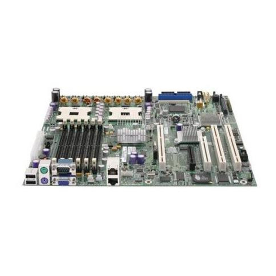
Product Overview Intel® Server Board SE7520BD2 Technical Product Specification Server Board Illustration The following figure provides a high-level illustration of the Server Board SE7520BD2. Figure 1. Top Side View of the Intel® Server Board SE7520BD2 Revision 1.3... -
Page 17: Mechanical Drawing
Intel® Server Board SE7520BD2 Technical Product Specification Product Overview Mechanical Drawing The following figure provides a mechanical illustration of the Server Board SE7520BD2. ® Figure 2. Intel Server Board SE7520BD2 Server Board Mechanical Drawing Revision 1.3 Intel Confidential... -
Page 18: Server Board Layout
Intel® Server Board SE7520BD2 Technical Product Specification Server Board Layout Figure 3 illustrates the functional blocks of the Server Board SE7520BD2 as well as the plug-in modules that the server board supports. Figure 3. Intel® Server Board SE7520BD2 SCSI System Block Diagram... -
Page 19: Figure 4. Intel® Server Board Se7520Bd2 Sata System Block Diagram
Intel® Server Board SE7520BD2 Technical Product Specification Product Overview Figure 4. Intel® Server Board SE7520BD2 SATA System Block Diagram Revision 1.3 Intel Confidential... -
Page 20: Identifying The Version Of An Intel® Server Board
Figure 5. Intel® Server Board SE7520BD2-V System Block Diagram Identifying the Version of an Intel® Server Board The version of an Intel® server board can be determined by decoding the last 3 digits of the board part number. Example : C44686-703 7=Fabrication (FAB) Number, 03 = Revision 3. -
Page 21: Memory Controller Hub (Mch)
When both DDR channels are populated and operating, they function in lock-step mode. For the Intel® E7520 MCH, the maximum supported DDR266 memory size is 32 GB, however the Server Board SE7520BD2 has 6 DIMM sites which limits this maximum memory size to 24 GB. The maximum supported DDR333 is 16 GB. -
Page 22: Pci Express (Pcie)
2.6.4 PCI Express (PCIe) The Intel® E7520 MCH is the first Intel® chipset to support the new PCI Express* high-speed serial I/O interface for superior I/O bandwidth. The scalable PCI Express interface complies with the PCI Express* Interface Specification, Rev 1.0a. The MCH provide three x8 PCI Express interfaces, each with a maximum theoretical bandwidth of 4 GB/s. -
Page 23: Table 1. Processor Support Matrix
3.6 GHz 2048KB Yes ** Note: ** BIOS P07 or greater is required to support the Intel® Xeon™ processor with 2MB L2 cache. The Server Board SE7520BD2 is designed to provide up to 120-A per processor. Processors with higher current requirements are not supported. -
Page 24: Multiple Processor Initialization
2.7.3 Processor VRD The Server Board SE7520BD2 has two VRDs (Voltage Regulator Down) providing the appropriate voltages to the installed processors. Each VRD is compliant with the VRD 10.1 specification and is designed to support current and next generation Intel® Xeon™ processors that require up to a sustained maximum of 105 A and peak support of 120 A. -
Page 25: Reset Configuration Logic
The baseboard as shipped from Intel’s factory will ship with a CEK spring snapped onto the bottom side of the board beneath each processor socket. The CEK spring is removable allowing for the use of non-Intel heat sink retention solutions. -
Page 26: Memory Sub-System Detail
Intel® Server Board SE7520BD2 Technical Product Specification Memory Sub-System Detail The Server Board SE7520BD2 supports both DDR-1 266MHz and 333MHz memory. For the server board, there are two DDR-1 channels (channels A and B) from the MCH, each supporting three DIMM slots. The channels can be configured to operate in dual-channel or single-channel mode. -
Page 27: Ddr-1 266 Memory
For DDR-I 266-MHz installation, 6 loads per channel are allowed on the Server Board SE7520BD2, although the Intel® E7520 chipset supports 8 loads. This means that for both single/dual rank DIMMs, the test setups previously listed can be populated with no further considerations. -
Page 28: Single-Channel Operation
The ECC used for DRAM provides Intel® SDDC x4 technology for x4 SDRAMs. DRAMs that are x8 use the same algorithm but will not have Intel® SDDC x4 technology, since at most only four bits can be corrected with this ECC. - Page 29 As seen in the following figure, potential mirroring pairs are DIMM 1A with DIMM 2B, or DIMM 1B with DIMM 2A. As a result, on the Server Board SE7520BD2 there are two supported configurations for memory mirroring: •...
-
Page 30: Figure 8. Memory Subsystem
Product Overview Intel® Server Board SE7520BD2 Technical Product Specification Figure 8. Memory Subsystem These symmetry requirements are a side effect of the hardware mechanism for maintaining two copies of all main memory data while ensuring that each channel has a full copy of all data in preparation for fail-down to single-channel operation. -
Page 31: C Bus Detail
0xA4 PCI Sub-System Detail 2.9.1 ICH5-R PCI Interface The Intel® 8280 ER I/O Controller Hub (ICH5-R) PCI interface is a multi-function device providing an upstream hub interface for access to several embedded I/O functions and features including: • PCI Local Bus Specification, Revision 2.3 with support for 33-MHz PCI operations. - Page 32 RAID. The ICH5 SATA RAID has two channels of SATA RAID support. It uses the LSI Logic SATA RAID stack, which is similar to Intel’s RAID stack. This will allow you have either RAID L level 0 or 1 support. For the above LSI* 53C1030 integrated SCSI firmware RAID, you only get one array.
- Page 33 ICH5-R’s port-routing logic determines whether a USB port is controlled by one of the UHCI controllers or by the EHCI controller. The Server Board SE7520BD2 has five USB ports: three in the back, two in the front. 2.9.1.8 The ICH5-R contains a Motorola* MC146818A-compatible real-time clock with 256 bytes of battery backed RAM.
-
Page 34: Table 6. Gpio On The Intel® Server Board Se7520Bd2
GPIO is NOT available) • GPIO resume power well: 8-15, 24-25, 27-28 • GPIO core power well: 0-7, 16-23, 32-34, 40-41, 48 Table 6. GPIO on the Intel® Server Board SE7520BD2 ICH5-R Signal Type PWR Well Tolerant Intel® Server Board SE7520BD2 Usage... -
Page 35: Pxh
Intel® Server Board SE7520BD2 Technical Product Specification Product Overview GPO48/GNT4# Output Core 3.3V FRB Timer Halt 2.9.1.10 Enhanced Power Management The ICH5-R’s power management functions include enhanced clock control, local and global monitoring support for 14 individual devices, and various low-power (suspend) states (e.g., Suspend-to-DRAM and Suspend-to-Disk). -
Page 36: Table 7. Slot 6 Pci-X Pin-Out
Product Overview Intel® Server Board SE7520BD2 Technical Product Specification The PCI-X Slot 6 has been modified to allow a third-party add-in riser card. This slot is capable of being populated with three types of devices: • Standard PCI 133-MHz compatible add-in card •... - Page 37 Intel® Server Board SE7520BD2 Technical Product Specification Product Overview Ground FRAME# IRDY# Ground +3.3V TRDY# DEVSEL# Ground PCIXCAP STOP# LOCK# +3.3V PERR# SMBCLK +3.3V SMBDAT SERR# Ground +3.3V PAR/ECC[0] C/BE[1]# AD[15] AD[14] +3.3V Ground AD[13] AD[12] AD[11] AD[10] Ground M66EN...
-
Page 38: Ultra-320 Scsi Controller
2.9.3 Ultra-320 SCSI Controller The Server Board SE7520BD2 provides an embedded dual-channel SCSI bus through the use of an LSI* AIC-1030C SCSI controller. The AIC-1030C controller contains two independent SCSI controllers that share a single 64-bit/100-MHz PCI-X mode 1 bus master interface as a multifunction device, packaged in a 456-pin BGA. -
Page 39: Figure 9. Mromb Implementation
Intel® Server Board SE7520BD2 Technical Product Specification Product Overview N-Channel FET 3.3V BSS138 3.3V IPN: 665805-001 4.7K 3.3V PCIX 100 Slot2 4.7K 3.3V 3.3V 3.3V AD(18)_IDSEL IDSEL 8.2K MROMB_IDSEL_N Internal to PXH Single Gate 4.7K 4.7K 4.7K 74LVT1G125 IPN: A54899-001... -
Page 40: Io Sub-System Detail
2.10.2 Intel® 3-Volt Advanced+ Boot Block Flash Memory The server board incorporates an Intel® 3 Volt Advanced+ Boot Block 28F320C3BD70 Flash memory component. The flash memory device interfaces to the server I/O via the 16-bit XBUS and contains the following: •... -
Page 41: Video Controller
2.10.3.1 Intel® 82541PI Gigabit Ethernet Controller The Intel® 82541PI Gigabit Ethernet controller is a single, compact component with an integrated Gigabit Ethernet Media Access Control (MAC) and physical layer (PHY) functions. The controller allows for Gigabit Ethernet implementation in a very small area. It integrates fourth-generation gigabit MAC design with fully integrated, physical layer circuitry to provide a standard IEEE 802.3 Ethernet interface for 1000BASE-T, 100BASE-TX, and 10BASE-T... -
Page 42: Db800 Differential Buffer
Serial ATA components. The DB800 accepts a single differential clock input from the CK409 clock synthesizer and produces eight buffered differential outputs. On the Server Board SE7520BD2, the SRC is connected to the ICH5-R, MCH, PXH, two PCI- Express slots and the Marvell* “Yukon” 88E8050 LAN. -
Page 43: Bios Architecture
These images are supplied by the device manufacturers and are not specified in this document. BIOS Functionality The BIOS for the Intel® Server Board SE7520BD2 is comprised of the following components: • The IA-32 core BIOS – This component contains most of the standard services and components found in an IA-32 system, e.g., PCI Resource manager, ACPI support,... - Page 44 BIOS Architecture Intel® Server Board SE7520BD2 Technical Product Specification Feature Name Comments Wake up (a) RTC (real time clock): S1/S4 (b) PME: S1/S4 (c) ring: S1/S4 (d) PS2 KB/MS: (e) USB: (f) power button: S1/S4/S5 USB Boot USB boot support for USB 1.1/2.0...
- Page 45 Intel® Server Board SE7520BD2 Technical Product Specification BIOS Architecture Feature Name Comments Hardware support for monitoring: Voltages, BMC will support it. Temperature, Fans BIOS Setup will provide options to disable onboard I/O Must be able to disable embedded Peripheral components...
- Page 46 BIOS Architecture Intel® Server Board SE7520BD2 Technical Product Specification Feature Name Comments Support for serial on LAN (SOL) Supported by Sahalee BMC Support for FRU LEDs Support for FRB-1/2/3 Support for EFI -32 EFI Rev. 1.1 Support for memory DDR266/333...
-
Page 47: Bios Identification String
Intel® Server Board SE7520BD2 Technical Product Specification BIOS Architecture Feature Name Comments Support for security PS/2 KB & MS lock Floppy write protection Video blanking Front panel lock Password protection Support for Boot quiet boot during POST quick boot during POST... -
Page 48: Hardware Requiring Bios Support
BIOS Architecture Intel® Server Board SE7520BD2 Technical Product Specification The system BIOS has the following unique BIOS ID: SE7520BD2. The following is a sample Production data string that is displayed during POST: SE7520BD20.86B.X02.01.00.0002.081320031156 3.1.3 Hardware Requiring BIOS Support The Intel® Server Board SE7520BD2 contains the following... -
Page 49: Bios Setup Utility
Intel® Server Board SE7520BD2 Technical Product Specification BIOS Architecture System State Window Logo/Diagnostic Window Current Activity Window When the CMOS is corrupt, the BIOS displays the following message: Press F1 for Setup and F2 to Continue The BIOS pauses at this message for 5 seconds. If no response is received, the BIOS continues the boot process using default setup settings. -
Page 50: Keyboard Commands
BIOS Architecture Intel® Server Board SE7520BD2 Technical Product Specification 3.2.2 Keyboard Commands The Keyboard Command Bar supports the following keyboard commands. Table 10. BIOS Setup Utility Keyboard Commands Option Description Enter Execute The Enter key is used to activate sub-menus when the selected feature is a sub-... -
Page 51: Menu Selection
Intel® Server Board SE7520BD2 Technical Product Specification BIOS Architecture Option Description Save and Exit Pressing F10 causes the following message to appear: Setup Confirmation Save Configuration changes and exit now? [Yes] [No] If “Yes” is selected and the Enter key is pressed, all changes are saved and Setup is exited. -
Page 52: Advanced Menu
BIOS Architecture Intel® Server Board SE7520BD2 Technical Product Specification System Date DAY MM/DD/YYYY Use [ENTER], [TAB] or [SHIFT- Configures the system date. TAB] to select a field. Default is [Tue 01/01/2002]. Day of the week is automatically Use [+] or [-] to configure system calculated. - Page 53 Intel® Server Board SE7520BD2 Technical Product Specification BIOS Architecture Cache L3 Displays cache L3 size. Visible only if the processor contains an L3 cache. CPU 2 CPUID Displays the CPUID of the processor. Cache L1 Displays cache L1 size. Cache L2 Displays cache L2 size.
-
Page 54: Table 14. Bios Setup Ide Configuration Menu Options
BIOS Architecture Intel® Server Board SE7520BD2 Technical Product Specification 3.2.5.2 IDE Configuration Sub-menu Table 14. BIOS Setup IDE Configuration Menu Options Feature Options Help Text Description IDE Configuration Onboard P-ATA Disabled Disabled: disables the Controls state of integrated P- Channels integrated P-ATA Controller. -
Page 55: Table 15. Mixed P-Ata-S-Ata Configuration With Only Primary P-Ata
Intel® Server Board SE7520BD2 Technical Product Specification BIOS Architecture IDE Detect Time Out Select the time out value for Primarily used with older IDE (Sec) detecting ATA/ATAPI device(s). devices with longer spin up times. ATA(PI) 80Pin Cable Host & Device... -
Page 56: Table 17. Bios Setup, Floppy Configuration Sub-Menu Selections
BIOS Architecture Intel® Server Board SE7520BD2 Technical Product Specification Block (Multi-Sector Disabled Disabled: The Data transfer from The Auto setting should work in Transfer) Mode Auto and to the device occurs one sector most cases. at a time. Auto: The data transfer from and to the device occurs multiple sectors at a time if the device supports it. -
Page 57: Table 18. Bios Setup, Super I/O Configuration Sub-Menu
Intel® Server Board SE7520BD2 Technical Product Specification BIOS Architecture 3.2.5.4 Super I/O Configuration Sub-menu Table 18. BIOS Setup, Super I/O Configuration Sub-menu Feature Options Help Text Description Configure Nat42x Super IO Chipset Serial Port A Address Disabled Allows BIOS to Select Serial Port A... -
Page 58: Table 20. Bios Setup, Usb Mass Storage Device Configuration Sub-Menu Selections
BIOS Architecture Intel® Server Board SE7520BD2 Technical Product Specification 3.2.5.5.1 USB Mass Storage Device Configuration Sub-menu Table 20. BIOS Setup, USB Mass Storage Device Configuration Sub-menu Selections Description Feature Options Help Text USB Mass Storage Device Configuration USB Mass Storage... - Page 59 Intel® Server Board SE7520BD2 Technical Product Specification BIOS Architecture Onboard NIC 2 ROM Disabled Enable/Disable OnBoard NIC 2 ROM. Grayed out if device is disabled. Enabled Onboard SCSI Disabled Enable/Disable OnBoard SCSI. Enabled Onboard SCSI ROM Disabled Enable/Disable OnBoard SCSI ROM.
-
Page 60: Table 22. Bios Setup, Memory Configuration Sub-Menu Selections
BIOS Architecture Intel® Server Board SE7520BD2 Technical Product Specification 3.2.5.7 Memory Configuration Sub-menu This sub-menu provides information about the DIMMs detected by BIOS. The DIMM number is printed on the baseboard next to each device. Table 22. BIOS Setup, Memory Configuration Sub-menu Selections... -
Page 61: Boot Menu
Intel® Server Board SE7520BD2 Technical Product Specification BIOS Architecture Memory Retest Disabled If "Enabled", BIOS will activate and retest all DIMMs on the next Enabled system boot. This option will automactically reset to "Disabled" on the next system boot. Memory Remap Feature... -
Page 62: Table 24. Bios Setup, Boot Settings Configuration Sub-Menu Selections
BIOS Architecture Intel® Server Board SE7520BD2 Technical Product Specification 3.2.6.1 Boot Settings Configuration Sub-menu Selections Table 24. BIOS Setup, Boot Settings Configuration Sub-menu Selections Feature Options Help Text Description Quick Boot Disabled Allows BIOS to skip certain tests while booting. This will decrease the time needed to boot the system. -
Page 63: Security Menu
Intel® Server Board SE7520BD2 Technical Product Specification BIOS Architecture 3.2.6.2.2 Removable Drive Sub-menu Selections Table 27. BIOS Setup, Removable Drives Sub-menu Selections Feature Options Help Text Description Removable Drives 1st Drive Varies Specifies the boot sequence from the available Varies based on system configuration. - Page 64 BIOS Architecture Intel® Server Board SE7520BD2 Technical Product Specification Clear User Immediately clears the user Admin uses this option to clear Password password. User password (Admin password is used to enter setup is required). This node is grayed out if Administrator password is not installed.
-
Page 65: Server Menu
Intel® Server Board SE7520BD2 Technical Product Specification BIOS Architecture NMI Control Disabled Default settings: Enabled For mBMC: “Disabled” Enable / disable NMI control for the front panel NMI button. For IMM: “Enabled” 3.2.8 Server Menu Table 30. BIOS Setup, Server Menu Selections... -
Page 66: Table 31. Bios Setup, System Management Sub-Menu Selections
BIOS Architecture Intel® Server Board SE7520BD2 Technical Product Specification OS Watchdog Timer Policy Stay On Controls the policy upon timeout. Stay on action will take no overt Reset action. Reset will force the Power Off system to reset. Power off will force the system to power off. -
Page 67: Table 32. Bios Setup, Serial Console Features Sub-Menu Selections
Intel® Server Board SE7520BD2 Technical Product Specification BIOS Architecture 3.2.8.2 Serial Console Features Sub-menu Selections Table 32. BIOS Setup, Serial Console Features Sub-menu Selections Feature Options Help Text Description Serial Console Features BIOS Redirection Port Disabled If enabled, BIOS uses the specified serial... -
Page 68: Exit Menu
BIOS Architecture Intel® Server Board SE7520BD2 Technical Product Specification ECC Event Logging Disabled Enables or Disables ECC Event Logging. Grayed out if "Critical Event Logging" option is disabled. Enabled PCI Error Logging Disabled Enables or Disables PCI Error Logging. Grayed out if "Critical Event Logging"... -
Page 69: Localization Details
CMOS checksum errors require that you enter Setup, check your settings, save your settings, and exit Setup. Localization Details The BIOS supports English, Spanish, French, German, and Italian. Intel provides translations for console strings in the supported languages. The language can be selected using the BIOS user interface. -
Page 70: Flash Architecture And Flash Update Utility
The flash ROM contains system initialization routines, the BIOS Setup Utility, and runtime support routines. The exact layout is subject to change, as determined by Intel. A 64-KB user block is available for user ROM code or custom logos. The flash ROM also contains initialization code in compressed form for onboard peripherals, such as SCSI, NIC and video controllers. - Page 71 Intel® Server Board SE7520BD2 Technical Product Specification BIOS Architecture • Microcode updates 3.5.2.1 Flash BIOS The BIOS flash utility is compatible with DOS, Microsoft* Windows* NT 4.0/2000/XP, and Linux operating environments. An afuXXX AMI Firmware Update utility (such as afudos, AFUWIN, afulnx, or AFUEFI) is required for a BIOS update.
-
Page 72: User Binary Area
BIOS Architecture Intel® Server Board SE7520BD2 Technical Product Specification • Boot to Linux and set up a floppy device. • Run the AFULNX utility as follows: ./afulnx /i<ROM filename> [/n][/p[b][n][c]] 3.5.2.5 Updating the BIOS from the EFI Shell • Make sure that the flash disk contains the ROM image and the AFUEFI utility. - Page 73 Intel® Server Board SE7520BD2 Technical Product Specification BIOS Architecture 3.5.4.1 BIOS Recovery The BIOS has a ROM image size of 2 MB. A standard 1.44MB floppy diskette cannot hold the entire ROM file due to the large file size. To compensate for this, a Multi-disk recovery method is available for BIOS recover (see Section 3.5.4.2 for further details).
-
Page 74: Update Oem Logo
BIOS Architecture Intel® Server Board SE7520BD2 Technical Product Specification For Example: C:\split AMIBOOT.ROM AMIBOOT 1024 • The above command will create files of size 1 MB each (1024 KB) with the names AMIBOOT.000, AMIBOOT.001... and so on. The number of files (or floppy disks) will depend upon the size of the AMIBOOT.ROM file. -
Page 75: Oem Binary
Intel® Server Board SE7520BD2 Technical Product Specification BIOS Architecture 3.5.5.2 Changing the OEMlogo for Microsoft* Windows* 98/2000/XP • Boot to Microsoft Windows 98/2000/XP. • Download OEMLOGO.exe, Rombuild.exe, RomFile, and NewOEMlogoImage to the hard drive. • Run the following command: OEMLogo <RomFileName> <NewOEMImageFileName> [/F or /FN or /N] Usage: OEMLogo <RomFileName>... - Page 76 BIOS Architecture Intel® Server Board SE7520BD2 Technical Product Specification Intel will provide the tools and reference code to help OEMs build a user binary. The user binary must adhere to the following requirements: • In order to be recognized by the BIOS and protected from runtime memory managers, the user binary must have an option ROM header (55AA, size).
-
Page 77: Pci Numeration
Intel® Server Board SE7520BD2 Technical Product Specification BIOS Architecture the CMOS bit in RTC. This is a bit address, not a byte address. The CMOS byte location is 1/8th of the 12-bit number, and the remainder is the starting bit position within that byte. For example, if the 12-bit number is 0109h, the user binary can use bit 1 of CMOS byte 0108h/8 or 021h. -
Page 78: Acpi Runtime Checkpoints
BIOS Architecture Intel® Server Board SE7520BD2 Technical Product Specification ACPI Runtime Checkpoints ACPI checkpoints are displayed when an ACPI capable operating system either enters or leaves a sleep state. The following table describes the type of checkpoints that may occur during ACPI sleep or wake events. -
Page 79: Platform Management Architecture
The Standard management model utilizes the feature set of a fully IPMI 2.0 compliant Sahalee Baseboard Management Controller (BMC). On the Server Board SE7520BD2 the Sahalee BMC is located on an optionally installed Flexible Management Module (FMM) that plugs into a dedicated server management connector on the baseboard. -
Page 80: Table 37. Power And Reset Control
Platform Management ArchitectureIntel® Server Board SE7520BD2 Technical Product Specification IPMI Channels, and Sessions Limited EMP (Emergency Management Port) - IPMI Messaging over Serial/Modem. This feature is also referred to as DPC (Direct Platform Control) over serial/modem. Serial/Modem Paging Serial/Modem Alerting over PPP using the Platform Event Trap (PET) -
Page 81: Table 38. Secure Mode Button Actions
Intel® Server Board SE7520BD2 Technical Product SpecificationPlatform Management Architecture Table 38. Secure Mode Button Actions ACPI Power Switch Sleep Switch Reset Switch NMI Switch ID Switch State S0 On Protected – No Protected – No Protected – No Unprotected Unprotected... -
Page 82: Standby
Platform Management ArchitectureIntel® Server Board SE7520BD2 Technical Product Specification FRONT PANEL Fault Power Temp Sensor Reset Power Front Panel Connector BASEBOARD PROC 1 & 2 - Therm Trip 1U PCI - IERR CPU 1&2 - Proc Hot - Temperature - VIDs... -
Page 83: Ipmi Messaging, Commands, And Abstractions Xxx
Intel® Server Board SE7520BD2 Technical Product SpecificationPlatform Management Architecture including the front panel Power Button, the baseboard RTC alarm signal, and power on request messages from the auxiliary IPMB connector and PCI SMBus. • Onboard NICs that support IPMI-over-LAN and LAN Alerting, Wake-On LAN, and Magic Packet* operation. -
Page 84: Private Management Buses
Management Controllers At the heart of platform management is a management controller. To support the tiered management model, the Server Board SE7520BD2 supports two different management controllers. Integrated onto the baseboard is the National Semiconductor* Mini-BMC (mBMC) to provide the functionality of the Essentials management tier. The Standard and Advanced modules electrically replace the Mini-BMC with the more full featured ‘Sahalee’... - Page 85 FRU Information Access. FRU (Field Replaceable Unit) information is non-volatile storage for serial number, part number, asset tag and other inventory information for the baseboard and chassis. The FRU implementation on SE7520BD2 includes write support for OEM-specific records. Revision 1.3...
- Page 86 Platform Management ArchitectureIntel® Server Board SE7520BD2 Technical Product Specification • Autonomous Event Logging. The management controller autonomously polls baseboard sensors and generates IPMI Platform Events, also called Event Messages, when an event condition is detected. The events are automatically logged to the System Event Log (SEL).
-
Page 87: Table 40. Mbmc Built-In Sensors
Intel® Server Board SE7520BD2 Technical Product SpecificationPlatform Management Architecture • Diagnostic Interrupt (Front Panel NMI) Handling • SMI/NMI status monitor (Standard and Advanced systems only) • System interface to the IPMB (via System Interface Ports) (Standard and Advanced systems only) •... -
Page 88: Table 41. Onboard Platform Instrumentaion Using The Mbmc
Platform Management ArchitectureIntel® Server Board SE7520BD2 Technical Product Specification Event / Readable Event Offset Assert / Sensor Name Sensor Type Reading Value / EventData Triggers Deassert Type Offsets Sensor Platform Alert Platform Event Platform Allert Specific – Trig Offset Trap generated Table 41. - Page 89 Intel® Server Board SE7520BD2 Technical Product SpecificationPlatform Management Architecture Event / Sensor Event Offset Assert / Readable Sensor Name Reading Event Data Record Type Triggers Deassert Value/Offsets Action Type Type Threshold Fault LED Tach Fan 3 [u][ c,nc] As & De...
-
Page 90: Table 42. Platform Instrumentation Sensors Using The Intel® Management Module
Platform Management ArchitectureIntel® Server Board SE7520BD2 Technical Product Specification Table 42. Platform Instrumentation Sensors using the Intel® Management Module Event / Readable Sensor Event Offset Assert / Sensor Name Sensor Type Reading Value / EventData Number Triggers Deassert Type Offsets... - Page 91 Intel® Server Board SE7520BD2 Technical Product SpecificationPlatform Management Architecture Event / Readable Sensor Event Offset Assert / Sensor Name Sensor Type Reading Value / EventData Number Triggers Deassert Type Offsets Sensor Memory Memory Specific Uncorrectable ECC – Trig Offset –...
- Page 92 Platform Management ArchitectureIntel® Server Board SE7520BD2 Technical Product Specification Event / Readable Sensor Event Offset Assert / Sensor Name Sensor Type Reading Value / EventData Number Triggers Deassert Type Offsets Threshold Tach Fan 2 [u,l][nr,c,nc] As & De Analog R, T –...
- Page 93 Intel® Server Board SE7520BD2 Technical Product SpecificationPlatform Management Architecture Event / Readable Sensor Event Offset Assert / Sensor Name Sensor Type Reading Value / EventData Number Triggers Deassert Type Offsets Presence Power Supply Status Sensor Failure Power Supply Specific As & De –...
- Page 94 Platform Management ArchitectureIntel® Server Board SE7520BD2 Technical Product Specification Event / Readable Sensor Event Offset Assert / Sensor Name Sensor Type Reading Value / EventData Number Triggers Deassert Type Offsets Digital State Asserted SMI Signal State Discrete – – –...
- Page 95 Intel® Server Board SE7520BD2 Technical Product SpecificationPlatform Management Architecture Event / Readable Sensor Event Offset Assert / Sensor Name Sensor Type Reading Value / EventData Number Triggers Deassert Type Offsets Digital Processor 1 Thermal Temp Transitioned to Non- Discrete As & De –...
-
Page 96: Essentials Management Features And Functionality
Platform Management ArchitectureIntel® Server Board SE7520BD2 Technical Product Specification Essentials Management Features and Functionality 4.2.1 Overview of mBMC The mini Baseboard Management Controller (mBMC) is an Application Specific Integrated Circuit (ASIC) with many peripheral devices embedded into it. The mBMC contains the logic needed for controlling the system, monitoring the sensors, and communicating with other systems and devices via various external interfaces. -
Page 97: Mbmc Self-Test
Intel® Server Board SE7520BD2 Technical Product SpecificationPlatform Management Architecture 4.2.2 mBMC Self-test The mBMC performs various tests as part of its initialization. If a failure is determined, the mBMC stores the error internally. A failure may be caused by a corrupt mBMC FRU, SDR, or SEL. -
Page 98: Messaging Interfaces
Platform Management ArchitectureIntel® Server Board SE7520BD2 Technical Product Specification P C I S M B u s S e n s o r D e v ic e s S M B u s F ro n t P a n e l Figure 12. -
Page 99: Table 43. Supported Channel Assigments
Intel® Server Board SE7520BD2 Technical Product SpecificationPlatform Management Architecture 4.2.5.1 Channel Management The mBMC supports two channels: • System interface • 802.3 LAN Table 43. Supported Channel Assigments Channel ID Media Type Interface Supports Sessions 802.3 LAN IPMB 1.0 Multi sessions... -
Page 100: Direct Platform Control (Ipmi Over Lan)
Platform Management ArchitectureIntel® Server Board SE7520BD2 Technical Product Specification 4.2.5.5 LAN Interface The baseboard supports one DPC LAN interface via a UDP port 26Fh. The mBMC supports a maximum of one simultaneous session across all authenticated channels. The baseboard implements gratuitous ARP support according to the IPMI 1.5 Specification. -
Page 101: Figure 13. Ipmi-Over-Lan
UDP port 26Fh is a ‘well-known port’ address that is specified to carry RMCP (Remote Management Control Protocol) formatted UDP datagrams. The onboard Intel network interface controllers contain circuitry that enables detecting and capturing RMCP packets that are received on Port 26Fh and making them available to the management controller via a ‘side-... -
Page 102: Wake On Lan / Power On Lan And Magic Packet Support
4.2.6.2 LAN Drivers and Setup The IPMI-over-LAN feature must be used with the appropriate Intel NIC Driver, and the NIC correctly configured in order for DPC LAN operation to occur transparently to the operating system and network applications. If an incorrect driver or NIC configuration is used, it is possible to get driver timeouts when the IPMI-over-LAN feature is enabled. -
Page 103: Watchdog Timer
Intel® Server Board SE7520BD2 Technical Product SpecificationPlatform Management Architecture 4.2.7.1 Wake On LAN in S4/S5 A configuration option is provided that allows the onboard NICs to be enabled to wake the system in an S4/S5 state, even if the operating system disabled Wake-On-LAN when it powered down the system. -
Page 104: Sensor Data Record (Sdr) Repository
Platform Management ArchitectureIntel® Server Board SE7520BD2 Technical Product Specification If the RTC changes during system operation, system management software must synchronize the mBMC time with the system time. If this is not done, the server should be reset so that the BIOS will pass the new time to the mBMC. -
Page 105: Table 46. Pef Action Priorities
Intel® Server Board SE7520BD2 Technical Product SpecificationPlatform Management Architecture • Reset • Diagnostic Interrupt • Alert The mBMC maintains an Event Filter table with 30 entries that is used to select the actions to perform. Also maintained is a fixed/read-only Alert Policy Table entry. No alert strings are supported. - Page 106 Platform Management ArchitectureIntel® Server Board SE7520BD2 Technical Product Specification Event Filter # Offset Mask Events Degraded Proc 1-2 FRB3 Assert Degraded Proc 1-2 FRB3 Deassert Degraded Proc 1-2 Hot Assert Degraded Proc 1-2 Hot Deassert Critical FP NMI Assert Critical...
-
Page 107: Nmi Generation
Intel® Server Board SE7520BD2 Technical Product SpecificationPlatform Management Architecture • Enabling/Disabling PEF. • Configuring Alert actions. • Selecting which pre-configured events trigger an alert. • Configuring the serial/modem and PPP communication and link parameters. • Configuring the alert destination information. -
Page 108: Figure 14. Power Supply Control Signals
Platform Management ArchitectureIntel® Server Board SE7520BD2 Technical Product Specification Figure 14 shows the power supply control signals and their sources. To turn the system on, the mBMC asserts the Power On signal and waits for the Power Good signal to assert in response, indicating that DC power is on. -
Page 109: System Reset Control
Intel® Server Board SE7520BD2 Technical Product SpecificationPlatform Management Architecture 2. If enabled, the mBMC sends a Set ACPI Power State command, indicating an S0 state to all management controllers whose SDR management device records indicate that they should receive the notification. -
Page 110: Fan Speed Control
The management controller firmware expects to find an LM30 temperature sensor on the front panel board. Thus, the ambient temperature-based fan speed control capability is not enabled by default for the Server Board SE7520BD2 as a baseboard-only product, but can be enabled via a management controller configuration change. - Page 111 Intel® Server Board SE7520BD2 Technical Product SpecificationPlatform Management Architecture Button, System ID LED, Status/Fault LED, and Chassis Intrusion Switch. Front panel control also includes the front panel lockout features. 4.3.4.1 Power Button After de-bouncing the front panel Power Button signal, the mBMC asserts the PWBTOUT signal to the chipset PWRBTN input.
-
Page 112: Table 50. Chassis Id Leds
Platform Management ArchitectureIntel® Server Board SE7520BD2 Technical Product Specification The LED can provide a mechanism for identifying one system out of a group of identical systems in a high density rack environment The Chassis Identify LED can be turned on either locally via the push-button signal, or by local or remote software using the IPMI Chassis Identify command. - Page 113 Intel® Server Board SE7520BD2 Technical Product SpecificationPlatform Management Architecture Critical Condition Any critical or non-recoverable threshold crossing associated with the following events: • Temperature, voltage, or fan critical threshold crossing • Power subsystem failure. The BMC asserts this failure whenever it detects a power control fault (e.g., the BMC detects that the system power is remaining on even though...
-
Page 114: Fru Information
Platform Management ArchitectureIntel® Server Board SE7520BD2 Technical Product Specification 4.3.5 FRU Information The platform management architecture supports providing FRU (Field Replaceable Unit) information for the baseboard and major replaceable modules in the chassis. ‘Major Module’ is defined as any circuit board in the system containing active electronic circuitry. -
Page 115: Table 52. Mbmc Built-In Sensors
Intel® Server Board SE7520BD2 Technical Product SpecificationPlatform Management Architecture [u,l][nr,c,nc] upper nonrecoverable, upper critical, upper noncritical, lower nonrecoverable, lower critical, lower noncritical uc, lc upper critical, lower critical Event Triggers are supported event generating offsets for discrete type sensors. The... -
Page 116: Table 53. Intel® Server Board Se7520Bd2 Platform Sensors For Essentials Management
• Power cycle • Timer Interrupt The following table shows the baseboard/platform sensors that are supported by the mBMC. Table 53. Intel® Server Board SE7520BD2 Platform Sensors for Essentials Management Event / Sensor Event Offset Assert / Readable Sensor Name... - Page 117 Intel® Server Board SE7520BD2 Technical Product SpecificationPlatform Management Architecture Event / Sensor Event Offset Assert / Readable Sensor Name Reading Event Data Record Type Triggers Deassert Value/Offsets Action Type Type Voltage Threshold Fault LED SCSI Core(1.8v) [u,l][ nr, c,nc] As & De...
-
Page 118: Server Management Block Diagram
Platform Management ArchitectureIntel® Server Board SE7520BD2 Technical Product Specification Event / Sensor Event Offset Assert / Readable Sensor Name Reading Event Data Record Type Triggers Deassert Value/Offsets Action Type Type Sate ID LED Chassis Identify Button Generic Deasserted As & De –... -
Page 119: Sio Keyboard And Mouse
KVM and web-based management traffic. The FML bus is Intel proprietary. Its electrical characteristics and protocols will be defined in a separate document. The bus operates at 8Mhz. It is meant to be point-to-point routing, and it largely follows the SMBUS protocols but uses separate wires for Data In (FML_SDA) and Data Out (FML_MDA_I2CSDA). -
Page 120: Lpc/Keyboard Controller Style Ports
Platform Management ArchitectureIntel® Server Board SE7520BD2 Technical Product Specification The FML_SINTEX functions as an alert signal while the bus is idle (between stop to start) and as a clock extension request from the slave device during the transaction itself. The behavior of the bus and the transactions on the bus are the same as in SMBus (Start, Stop, repeated start …). -
Page 121: C Interfaces
Intel® Server Board SE7520BD2 Technical Product SpecificationPlatform Management Architecture 4.6.6 C Interfaces The FMM incorporates two master/slave I C interfaces (I C interfaces 0 and 1) and four master- only I C interfaces (I C interfaces 2, 3, 4 and 5). All I... -
Page 122: Interrupts
Platform Management ArchitectureIntel® Server Board SE7520BD2 Technical Product Specification 4.6.8 Interrupts The module can receive interrupt events on the pins assigned to XINTx inputs. Two of the XINTs available on the Sahalee are used internally by the KVM and the private NIC function associated with the KVM. -
Page 123: Wake Events
Intel® Server Board SE7520BD2 Technical Product SpecificationPlatform Management Architecture 4.6.10.5 S4 State The S4 state is called Suspend to Disk. From a hardware perspective, it is equivalent to an S5 state. The operating system is responsible for saving the system context in a special partition on the hard drive. -
Page 124: System Status Indicators/Leds
Platform Management ArchitectureIntel® Server Board SE7520BD2 Technical Product Specification 4.6.13.1 Power Management Event (PME)# PME# signals from PCI-X slots on each PCI-X buses are connected to the PXH PME# signals. These PME# signals from both PCI-X buses are also ANDed and then wire-Ored with PCI Express slots and then routed to a ICH GPIO. -
Page 125: Figure 15. Front Panel Pinout
17. USB port 18. Chassis intrusion 19. SMBus The Server Board SE7520BD2 can also be converted into a rack installation in which the following are also supported on the front panel but are not accessible/visible in the pedestal chassis. •... -
Page 126: Table 54. Front Panel Color Attributes
Platform Management ArchitectureIntel® Server Board SE7520BD2 Technical Product Specification Table 54. Front Panel Color Attributes Name Color Condition Description Green Power On Power/Sleep Green BLINK Sleep (S1) Power Off (also S4) Green System Ready / No Alarm Green BLINK System Ready but degraded: some CPU Fault, DIMM killed... -
Page 127: Error Reporting And Handling
When errors are encountered during POST, error messages or codes are either displayed to the video screen, or if prior to video initialization, reported through a series of audio beep codes. The error codes are defined by Intel and whenever possible are backward compatible with error codes used on earlier platforms. -
Page 128: Frb-1 - Bsp Self-Test Failures
Error Reporting and Handling Intel® Server Board SE7520BD2 Technical Product Specification 5.2.3 FRB-1 – BSP Self-Test Failures In addition to the FRB-3 and FRB-2 timers, the BIOS provides an FRB-1 watchdog timer. Early in POST, the BIOS checks the Built-in Self Test (BIST) results of the BSP. If the BSP fails BIST, the BIOS requests the BMC to disable the BSP. -
Page 129: Error Messages And Error Codes
Intel® Server Board SE7520BD2 Technical Product Specification Error Reporting and Handling If a bad processor is removed from the system and is replaced with a terminator module, the BMC automatically detects this condition and clears the status flag for that processor during the next boot. - Page 130 Error Reporting and Handling Intel® Server Board SE7520BD2 Technical Product Specification Error Code Error Message Response 0010 Floppy Controller Failure Warning 0012 CMOS Date/Time Not Set Warning 0040 Refresh timer test failed Halt 0042 CMOS Display Type Wrong Pause 0043 <INS>...
-
Page 131: Post Error Beep Codes
Intel® Server Board SE7520BD2 Technical Product Specification Error Reporting and Handling Error Code Error Message Response 84FF System Event Log Full Warning The following table lists error codes that are sent to the MM for error logging as BMC pass- through commands. -
Page 132: Checkpoints
Error Reporting and Handling Intel® Server Board SE7520BD2 Technical Product Specification Table 57. POST Error Beep Codes Number of Beeps Description Memory refresh timer error. Main memory read / write test error. Keyboard controller BAT test error. Table 58. Troubleshooting BIOS Beep Codes... -
Page 133: Table 59. Post Progress Code Led Example
Intel® Server Board SE7520BD2 Technical Product Specification Error Reporting and Handling Red bits = 1010b = Ah Green bits = 1100b = Ch Since the red bits correspond to the upper nibble and the green bits correspond to the lower nibble, the two are concatenated to be ACh. -
Page 134: Error Logging
Error Reporting and Handling Intel® Server Board SE7520BD2 Technical Product Specification 0EAh MEM_ERR_TIMING 0EBh MEM_ERR_REG_CAS_3 0ECh MEM_ERR_NONREG_MIX 0EDh MEM_ERR_CAS_LATENCY 0EEh MEM_ERR_SIZE_NOT_SUPPORTED 0EFh MEM_ERR_POPULATION_ORDER 0F0h SYS_FREQ_ERR (Flag for Unsupported System Bus Freq) 0F1h DIMM_ERR_CFG_MIX (Usupported DIMM mix) 0F2h DQS_FAILURE (indicates DQS failure) -
Page 135: Smi Handler
Intel® Server Board SE7520BD2 Technical Product Specification Error Reporting and Handling 5.4.2 SMI Handler The SMI handler is used to handle and log system level events that are not visible to the server management firmware. If the SEL Error Logging in Setup is disabled, no SMI signals are generated on system errors. -
Page 136: Logging Format Conventions
Error Reporting and Handling Intel® Server Board SE7520BD2 Technical Product Specification 5.4.2.5 Processor Failure The BIOS detects processor BIST failure and logs this event. The failed processor can be identified by the first OEM data byte field in the log. For example, if processor 0 fails, the first OEM data byte will be 0. -
Page 137: Table 62. Examples Of Event Data Field Contents For Memory Errors
Intel® Server Board SE7520BD2 Technical Product Specification Error Reporting and Handling Sensor Type See Table 30.3 in [IPMI_1]. 0xC for memory errors Sensor Number Number of sensor that generated this event Unique value for each type of event because IPMI specification requires it that way. -
Page 138: Table 63. Pci Error Events
Error Reporting and Handling Intel® Server Board SE7520BD2 Technical Product Specification 5.4.3.2 PCI Error Events Table 63. PCI Error Events Field IPMI Definition Intel® Server Board SE7520BD2 BIOS Specific Implementation Generator ID 7:1 System software ID or IPMB slave 0x3 for system BIOS address. -
Page 139: Table 65. Frb-2 Error Events
Intel® Server Board SE7520BD2 Technical Product Specification Error Reporting and Handling 5.4.3.3 FRB-2 Error Events Table 65. FRB-2 Error Events Field IPMI Definition Intel® Server Board SE7520BD2 BIOS Specific Implementation Generator ID 7:1 System software ID or IPMB slave 0x3 for system BIOS address. -
Page 140: Post Code Checkpoints
Error Reporting and Handling Intel® Server Board SE7520BD2 Technical Product Specification 5.4.4 POST Code Checkpoints Table 67. POST Code Checkpoints Diagnostic LED Decoder Description Checkpoint G=Green, R=Red, A=Amber Disable NMI, parity, video for EGA, and DMA controllers. Initialize BIOS, POST, Run-time data area. Initialize BIOS modules on POST entry and GPNV area. - Page 141 Intel® Server Board SE7520BD2 Technical Product Specification Error Reporting and Handling Diagnostic LED Decoder Description Checkpoint G=Green, R=Red, A=Amber Allocate memory for ADM module and uncompress it. Give control to ADM module for initialization. Initialize language and font modules for ADM.
-
Page 142: Boot Block Initialization Code Checkpoints
Error Reporting and Handling Intel® Server Board SE7520BD2 Technical Product Specification Diagnostic LED Decoder Description Checkpoint G=Green, R=Red, A=Amber End of POST initialization of chipset registers. Save system context for ACPI. Passes control to OS Loader (typically INT19h). 5.4.5 Boot Block Initialization Code Checkpoints The boot block initialization code sets up the chipset, memory and other components before system memory is available. -
Page 143: Boot Block Recovery Code Checkpoint
Intel® Server Board SE7520BD2 Technical Product Specification Error Reporting and Handling 5.4.6 Boot Block Recovery Code Checkpoint The boot block recovery code gets control when the BIOS determines that a BIOS recovery needs to occur because the user has forced the update or the BIOS checksum is corrupt. The following table describes the type of checkpoints that may occur during the boot block recovery portion of the BIOS. -
Page 144: Dim Code Checkpoints
Error Reporting and Handling Intel® Server Board SE7520BD2 Technical Product Specification ROM image mismatch Infinite long beep Recovery successful 5.4.7 DIM Code Checkpoints The Device Initialization Manager (DIM) module gets control at various times during BIOS POST to initialize different BUSes. The following table describes the main checkpoints where the DIM module is accessed. -
Page 145: Reliability, Availability And Serviceability (Ras) Features
Intel® Server Board SE7520BD2 Technical Product Specification Error Reporting and Handling Reliability, Availability and Serviceability (RAS) Features 5.5.1 Memory RAS features The MCH is designed to bring enterprise level reliability, availability, serviceability, usability, and manageability to the DP server platform. The MCH supports ACPI power management, and wake-from-LAN to maximize platform stand-by flexibility. -
Page 146: Ras Features Of Fsb
Error Reporting and Handling Intel® Server Board SE7520BD2 Technical Product Specification When the hardware detects that a packet is corrupted, a link level retry mechanism is used to perform a retry of the packet that was corrupted and all the following packets. Although this interrupts the delivery of packets and slows down communication, it does maintain link integrity. -
Page 147: Rolling Bios
Intel® Server Board SE7520BD2 Technical Product Specification Error Reporting and Handling down the system. The SMBus on the baseboard is pulled up to 3.3V standby and requires the RMC not to pull up this open-drain bus. Having duplicate pull-ups may break the signal integrity timing characteristics required by the SMBus protocol. -
Page 148: Connector Pin-Outs And Jumper Blocks
Connector Pin-outs and Jumper BlocksIntel® Server Board SE7520BD2 Technical Product Specification Connector Pin-outs and Jumper Blocks Board Connector Pin-outs Table 72. Board Connector Matrix Connector Quantity Connector Type Pin Count Memory DIMM Sockets PCI Express Card Edge PCI X 133MHz... -
Page 149: Table 74. Oem Rmc 8-Pin (Remote Management Card Support)
Intel® Server Board SE7520BD2 Technical Product SpecificationConnector Pin-outs and Jumper Blocks Table 74. OEM RMC 8-pin (Remote Management Card Support) Name Description SMBUS_SDA SMBus data on baseboard peripheral bus. This allows direct access to HECETA through the open-drain SMBus v2.0 specification. There is a baseboard pull-up, and RMC (Remote Management Card) should not be pulling should not be pulling this up. -
Page 150: Table 76. Eps12V 2X4 Connector
Connector Pin-outs and Jumper BlocksIntel® Server Board SE7520BD2 Technical Product Specification Table 76. EPS12V 2x4 Connector Pin No. Signal Name +12V +12V +12V +12V Table 77. EPS12V 1x5 Connector Pin No. Signal Name SMBus clock SMBus Data GND Return Sense +3.3V Sense... -
Page 151: Table 79. Front Panel Connector
Intel® Server Board SE7520BD2 Technical Product SpecificationConnector Pin-outs and Jumper Blocks Table 79. Front Panel Connector Signal Name Signal Name P5V_STBY P5V_STBY FP_PWR_LED_N FP_COOL_FLT_LED_N FP_SYS_FLT_STATUS_LED_N HD_LED_ACT_N P5V_STBY FP_PWR_BTN_N NICA_ACT_LED_N NICA_LINK_LED_N FP_RST_BTN_N ICH5_SMBDAT ICH5_SMBCLK FP_SLPBTN_N FP_CHASSIS_INTRUDER_N NICB_ACT_LED_N FP_NMI_BTN_N NICB_LINK_LED_N P5V_STBY P5V_STBY... -
Page 152: Table 82. Sata Connector
Connector Pin-outs and Jumper BlocksIntel® Server Board SE7520BD2 Technical Product Specification Table 82. SATA Connector Signal Name S-ATA0_RX_P S-ATA0_RX_N S-ATA0_TX_P S-ATA0_TX_N Table 83. Battery Holder Signal Name VBAT VBAT Table 84. Piezo* Speaker Signal Name SPEAKER_OUT 1 Table 85. SCSI LED Connector... -
Page 153: Table 88. Fan 1 And Fan 2 (3 Pin + 2 Pin)
Intel® Server Board SE7520BD2 Technical Product SpecificationConnector Pin-outs and Jumper Blocks Table 88. Fan 1 and Fan 2 (3 Pin + 2 Pin) Signal Name Ground Fan Power Fan Tach Signal Name Fan LED Fan Presence Table 89. Fan 3 and Fan 4... -
Page 154: Board Jumper Blocks
Connector Pin-outs and Jumper BlocksIntel® Server Board SE7520BD2 Technical Product Specification Board Jumper Blocks 6.2.1 Rolling BIOS Bank Selection Jumper A single jumper on a two-pin header offers two possible positions: jumper on or jumper off. Jumper on indicates a Flash Recovery and jumper off indicates normal operation. -
Page 155: Cmos Clear
Intel® Server Board SE7520BD2 Technical Product SpecificationConnector Pin-outs and Jumper Blocks 6.2.4 CMOS Clear Table 94. CMOS Clear Jumper Setting Jumper Description Setting J2H1 CMOS Clear 1-2: CMOS Clear by BMC (default) 2-3: CMOS Clear Force Erase Procedure of CMOS Clear by BMC: Push power botton to power off, and then pressed the reset botton continually, then push the power botton once. -
Page 156: Environmental Specifications
Environmental Specifications Intel® Server Board SE7520BD2 Technical Product Specification Environmental Specifications Environmental Specifications and Cooling Requirements Non-operating temperature requirements: • From –40 degrees C to 70 degrees C Operating temperature requirements: • From 5 degrees C to 50 degrees C Voltage tolerance of all system power supply rails: •... -
Page 157: Power Supply Requirements
Intel® Server Board SE7520BD2 Technical Product Specification Environmental Specifications Power Supply Requirements 7.2.1 Baseboard Power Budget Table 95. Baseboard Power Budget Power Budget for Intel® Server Board SE7520BD2 Output Average Current Items Utilize Average Mother Board Q'ty Factor Power +5 V +3.3 V... - Page 158 Environmental Specifications Intel® Server Board SE7520BD2 Technical Product Specification 3.3V / 1.17A 2.70 1.080 1.5V / 5 A 5.25 1.3275 0.68 1.5 V VRD Eff @80% Memory DDR 266 DDR 2.5V (HIP6311)) 36.31 3.78 Vtt 1.25V (Linear) 2.00 9.08 2.5 V VRD Eff @80% 82541PI 0.70...
- Page 159 Intel® Server Board SE7520BD2 Technical Product Specification Environmental Specifications CPU Fan 100% 38.40 0.48 PCI 32 Bit (5V) 10.00 2.00 2.280 0.40 0.20 0.375 PCI-X 100 (3.3V) 20.00 4.00 4.560 0.40 0.040 PCI-X (266/1.5V, 133/3.3V) 10.00 2.00 2.280 0.40 0.020 PCI EXPRESS (3.3V)
-
Page 160: Voltages Supported
+5v Standby. High-frequency processor support will need a ~650W power supply, which is not yet defined. Other voltages required by the design are derived from linear and switching regulators. Refer to the modified power supply specification for additional information. Table 96. Intel® Server Board SE7520BD2 Board Voltage Table Voltage Net Name... -
Page 161: Standby Powered Device Map
Intel® Server Board SE7520BD2 Technical Product Specification Environmental Specifications 7.2.3 Standby Powered Device Map The following components on the Server Board SE7520BD2 require standby power when the system is in S4 or S5 sleep states: • Server I/O: +3.3VSB •... -
Page 162: Figure 17. Reset And Powergood Timings
Environmental Specifications Intel® Server Board SE7520BD2 Technical Product Specification Additional Details: SB_VTT_PWRGD is a delayed copy (minimum 1msec) of FSB VTT regulator VTT_PWRGD when the VTT_PWRGD transitions from low to high. VR0_SYS_ENABLE is generated based on the glue logic shown in the PLD plus SB_VTT_PWRGD plus an additional minimum 1msec delay. -
Page 163: Figure 18. Intel® Server Board Se7520Bd2 Power Sequencing Diagram
P12V_CPU (0 & 1) When all are good P3V3 N12V PS_PWR_GD P3V3_AUX_SWITCH P1V8_SCSI P_VTT PV_SCSI (A&B) P2V5_VIDEO P1V5 P1V8 P_VCCP0 If CPU1 P_VCCP1 Present P1V5_PXH Time not to scale Figure 18. Intel® Server Board SE7520BD2 Power Sequencing Diagram Revision 1.3 Intel Confidential... -
Page 164: Airflow Requirements
It is the responsibility of the system integrator that chooses not to use Intel developed server building blocks to consult vendor datasheets and operating parameters to determine the amount of airflow required for their specific application and environmental conditions. -
Page 165: Product Emc Compliance
7.5.2 Product EMC Compliance The Server Board SE7520BD2 system has been tested and verified to comply with the following electromagnetic compatibility (EMC) regulations when installed in a compatible Intel® host system. For information on compatible host system(s), contact your local Intel representative. -
Page 166: Product Regulatory Compliance Markings
Environmental Specifications Intel® Server Board SE7520BD2 Technical Product Specification 7.5.4 Product Regulatory Compliance Markings This product is provided with the following Product Certification Markings: • cURus Recognition Mark • CE Mark • Russian GOST Mark • Australian C-Tick Mark •... - Page 167 Intel® Server Board SE7520BD2 Technical Product Specification Environmental Specifications ADVARSEL! Lithiumbatteri - Eksplosionsfare ved fejlagtig håndtering. Udskiftning må kun ske med batteri af samme fabrikat og type. Levér det brugte batteri tilbage til leverandøren. ADVARSEL Lithiumbatteri - Eksplosjonsfare. Ved utskifting benyttes kun batteri som anbefalt av apparatfabrikanten.
-
Page 168: Other Useful Information
Other Useful Information Intel® Server Board SE7520BD2 Technical Product Specification Other Useful Information Platform Confidence Test (PCT) See the system board Resource CD. The executable is named BYOPCT. Intel Confidential Revision 1.3... -
Page 169: Appendix A - Known Errata
Fixed Intel® Xeon™ E0 SL7DP CPU micro code is missing Fixed Intel® Server Chassis SC6300 Chassis HSBP is missing the driver under the Microsoft Windows* 2003 and Windows* 2000 Fixed Front side bus sequence mismatch warning message with P03 BIOS... - Page 170 The error message falsely conveys that the board failed to execute BIOS code and failed to disable a timer before expiration. Intel found that this false error message is caused by the onboard platform instrumentation not consistently recognizing the BIOS command to disable the timer.
- Page 171 Problem When using an Intel® Xeon™ Processor E0 stepping Sl7DP processor on the Intel® Server Board SE7520BD2, an error may display indicating “CPU micro code missing information.” Implication This issue occurs when the processor microcode is old and needs to be updated.
- Page 172 Workaround A driver has been posted to fix this issue. Status The driver has been posted on the Intel support website to fix this issue (see URL below). Please use the *.inf posted on the support.intel.com website for Microsoft Windows 2003 and all of the chassis products: Microsoft Windows* 2000 Backplane Driver [WIN2K_HSBP_INF_FILE.EXE]...
- Page 173 6GB system memory Problem When a customer uses a total of 6GB or more memory on an Intel® Server Board SE7520BD2 under Microsoft Windows* 2003 server edition or Microsoft Windows* 2000 operating systems, all of the system memory is not recognized.
- Page 174 ONLY for the Intel® Server Board SE7520BD2. Workaround Issue was already fixed in version -004 of the labels. According to the Intel EPSD ECO roadmap, the new label should cut in to the boxed boards in WW01,05. Status Intel will fix this issue with ECO .
- Page 175 No workaround to this issue due to driver development is OS vendor’s responsibility. Status Intel will not fix this issue unless Red Hat* develops the driver to support this function. Boxboard Configuration Label has incorrect SSI Front Panel Connector pin out.
- Page 176 NIC. Implication The wrong configuration label may confuse some channel customers. Workaround Intel® Server Board SE7520BD2 C71063-005 and below will be fixed in WW10 with C71063-006 and with label C71061-005 Intel® Server Board SE7520BD2SCSI C71062-005 and below will be fixed in WW10 with C71062-006 and with label C71061-005 Intel®...
-
Page 177: Glossary
Intel® Server Board SE7520BD2 Technical Product Specification Other Useful Information Glossary This appendix contains important terms used in the preceding chapters. For ease of use, numeric entries are listed first (e.g., “82460GX”) with alpha entries following (e.g., “AGP 4x”). Acronyms are then entered in their respective place, with non-acronyms following. -
Page 178: Reference Documents
• Platform Management FRU Information Storage Definition, Version 1.0. 1998. Intel Corporation, Hewlett-Packard Company, NEC Corporation, Dell Computer Corporation. http://developer.intel.com/design/servers/ipmi/spec.htm • Server Power Control White Paper, Revision 0.93. November 5, 1998. Intel Corporation. • The SMBus Specification, Intel Corporation Processor •... - Page 179 Intel® Server Board SE7520BD2 Technical Product Specification Other Useful Information • Extensible Firmware Interface Reference Specification, Version 1.0., http://www.intel.com/technology/efi/index.htm • Extensible Firmware Interface Reference Specification, Version 1.1, http://www.intel.com/technology/efi/index.htm • Specifications for Teac America 3.5 inch Desktop and Notebook Floppy Drives, http://www.teac.com/dsp/catalog.html...
Need help?
Do you have a question about the SE7520BD2 and is the answer not in the manual?
Questions and answers