
Subscribe to Our Youtube Channel
Related Manuals for Intel S2400SC


Summary of Contents for Intel S2400SC
- Page 1 Intel Server Board S2400SC ® Technical Product Specification Intel order number G36516-002 Revision 2.0 December, 2013 Platform Collaboration and Systems Division – Marketing...
-
Page 2: Oct 2012
Revision History Intel® Server Board S2400SC TPS Revision History Date Revision Number Modifications April 2012 Initial release. May 2012 Updated the following: Figure 7 Tables 16, 58, and 59 Section 3.2.2 Section 6.11.4 Oct 2012 Updated Table 1 Jan 2013 1.21... - Page 3 INFRINGEMENT OF ANY PATENT, COPYRIGHT OR OTHER INTELLECTUAL PROPERTY RIGHT. A "Mission Critical Application" is any application in which failure of the Intel Product could result, directly or indirectly, in personal injury or death. SHOULD YOU PURCHASE OR USE INTEL'S PRODUCTS FOR ANY SUCH MISSION...
-
Page 4: Table Of Contents
Chapter Outline ...................... 1 Server Board Use Disclaimer ................. 1 2. Overview ..........................2 ® Intel Server Boards S2400SC Feature Set ............2 Server Board Layout ....................4 2.2.1 Server Board Connector and Component Layout ........... 4 2.2.2 Server Board Mechanical Drawings ............... 7 2.2.3... - Page 5 Intel® Server Board S2400SC TPS Table of Contents 3.3.22 KVM/Serial Over LAN (SOL) Function ..............38 3.3.23 On-board Serial Attached SCSI (SAS)/Serial ATA (SATA) Support and Options .. 39 Integrated Baseboard Management Controller (BMC) Overview ......41 3.4.1 Super I/O Controller ..................... 42 3.4.2...
- Page 6 Table of Contents Intel® Server Board S2400SC TPS 6.11.8 Thermal Sensor Input to Fan Speed Control ............66 6.11.9 Memory Thermal Throttling .................. 67 6.12 Messaging Interfaces ................... 68 6.12.1 User Model ......................68 6.12.2 IPMB Communication Interface ................68 6.12.3...
- Page 7 Intel® Server Board S2400SC TPS Table of Contents I/O Connectors ..................... 92 8.5.1 VGA Connector ....................92 8.5.2 SATA Connectors ....................93 8.5.3 Serial Port Connectors ..................94 8.5.4 USB Connector ....................94 Fan Headers ......................95 9. Jumper Blocks ........................97 BIOS Default (CMOS Clear) and Password Clear Usage Procedure ....
- Page 8 Server Board S2400SC – Mounting Hole Locations (2 of 2)........ 8 ® Figure 5. Intel Server Boards S2400SC – Major Connector Pin-1 Locations (1 of 2) ....9 ® Figure 6. Intel Server Boards S2400SC – Major Connector Pin-1 Locations (2 of 2) ....10 ®...
- Page 9 Intel® Server Board S2400SC TPS List of Tables List of Tables ® Table 1. Intel Server Board S2400SC Feature Set ..............2 ® Table 2. Intel Server Board S2400SC Component Layout ............5 Table 3. Mixed Processor Configurations .................. 18 Table 4.
- Page 10 List of Tables Intel® Server Board S2400SC TPS Table 40. Internal USB Connector Pin-out (J1C2) ..............95 Table 41. Pin-out of Internal Low-Profile USB Connector for Solid State Drive (J2E1) ....95 Table 42. Internal Type A USB Port Pin-out (J1J1) ..............95 Table 43.
- Page 11 Intel® Server Board S2400SC TPS List of Tables <This page is intentionally left blank.> Revision 2.0 Intel order number G36516-002...
-
Page 13: Introduction
It is the responsibility of the system integrator who chooses not to use Intel developed server building blocks to consult vendor datasheets and operating parameters to determine the amount of airflow required for their specific application and environmental conditions. -
Page 14: Overview
Overview Intel® Server Board S2400SC TPS Overview ® The Intel Server Board S2400SC is monolithic printed circuit boards (PCBs) with features designed to support the pedestal and rack server markets. Intel Server Boards S2400SC Feature Set ® ® Table 1. Intel... - Page 15 One internal Type-A USB 2.0 port. One 9pin USB header for eUSB SSD. ® One 1x7 pin header for optional Intel Local Control Panel support One SSI-compliant 24-pin front control panel header. Integrated 2D video controller.
-
Page 16: Server Board Layout
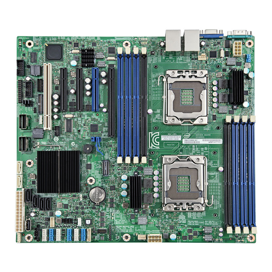
Overview Intel® Server Board S2400SC TPS Server Board Layout ® Figure 1. Intel Server Board S2400SC Layout 2.2.1 Server Board Connector and Component Layout The following figure shows the layout of the server board. Each connector and major component is identified by a number or letter, and a description is given in the below figure. -
Page 17: Figure 2. Intel ® Server Board S2400Sc Layout
Intel® Server Board S2400SC TPS Overview ® Figure 2. Intel Server Board S2400SC Layout ® Table 2. Intel Server Board S2400SC Component Layout Description Description Slot 2, 32bit/33MHz PCI System fan 3 header Slot 3, PCI Express* Gen2 x4 (x8... - Page 18 Overview Intel® Server Board S2400SC TPS Description Description processor) Slot 6, PCI Express* Gen3 x16, support HDD LED header riser card DIMM sockets from Processor 2 socket Type A USB header (Channel D, E, F) Diagnostic and identify LEDs IPMB header...
-
Page 19: Server Board Mechanical Drawings
Intel® Server Board S2400SC TPS Overview 2.2.2 Server Board Mechanical Drawings ® Figure 3. Intel Server Board S2400SC – Mounting Hole Locations (1 of 2) Revision 2.0 Intel order number G36516-002... -
Page 20: Figure 4. Intel Server Board S2400Sc - Mounting Hole Locations (2 Of 2)
Overview Intel® Server Board S2400SC TPS ® Figure 4. Intel Server Board S2400SC – Mounting Hole Locations (2 of 2) Intel order number G36516-002 Revision 2.0... -
Page 21: Figure 5. Intel Server Boards S2400Sc - Major Connector Pin-1 Locations (1 Of 2)
Intel® Server Board S2400SC TPS Overview ® Figure 5. Intel Server Boards S2400SC – Major Connector Pin-1 Locations (1 of 2) Revision 2.0 Intel order number G36516-002... -
Page 22: Figure 6. Intel Server Boards S2400Sc - Major Connector Pin-1 Locations (2 Of 2)
Overview Intel® Server Board S2400SC TPS ® Figure 6. Intel Server Boards S2400SC – Major Connector Pin-1 Locations (2 of 2) Intel order number G36516-002 Revision 2.0... -
Page 23: Figure 7. Intel Server Boards S2400Sc - Primary Side Keepout Zone
Intel® Server Board S2400SC TPS Overview ® Figure 7. Intel Server Boards S2400SC – Primary Side Keepout Zone Revision 2.0 Intel order number G36516-002... -
Page 24: Figure 8. Intel Server Boards S2400Sc - Primary Side Card Side Keepout Zone
Overview Intel® Server Board S2400SC TPS ® Figure 8. Intel Server Boards S2400SC – Primary Side Card Side Keepout Zone Intel order number G36516-002 Revision 2.0... -
Page 25: Figure 9. Intel Server Boards S2400Sc - Primary Side Air Duct Keepout Zone
Intel® Server Board S2400SC TPS Overview ® Figure 9. Intel Server Boards S2400SC – Primary Side Air Duct Keepout Zone Revision 2.0 Intel order number G36516-002... -
Page 26: Server Board Rear I/O Layout
Overview Intel® Server Board S2400SC TPS ® Figure 10. Intel Server Boards S2400SC – Second Side Keepout Zone 2.2.3 Server Board Rear I/O Layout The following drawing shows the layout of the rear I/O components for the server boards. Intel order number G36516-002... - Page 27 Intel® Server Board S2400SC TPS Overview Serial Port A Diagnostic LEDs ID LED Video System Status LED NIC Port 1 (1 Gb)_USB_0-1 NIC Port 2 (1 Gb)_USB_2-3 ® Figure 11. Intel Server Boards S2400SC Rear I/O Layout Revision 2.0 Intel order number G36516-002...
-
Page 28: Functional Architecture
The architecture and design of the Intel Server Board S2400SC is based on the Intel C600 ® ® chipset. The chipset is designed for systems based on the Intel Xeon processor in an FC-LGA ® ® 1356 Socket B2 package with Intel QuickPath Interconnect (Intel QPI). -
Page 29: Processor Socket Assembly
Processor Population rules Note: Although the server board does support dual-processor configurations consisting of different processors that meet the defined criteria below, Intel does not perform validation testing of this configuration. For optimal system performance in dual-processor configurations, Intel recommends that identical processors be installed. -
Page 30: Table 3. Mixed Processor Configurations
(highest common speed) and an error is reported. Processors which have different Intel Quickpath (QPI) Link Frequencies may operate together if they are otherwise compatible and if a common link frequency can be selected. The common link frequency would be the highest link frequency that all installed processors can achieve. - Page 31 Intel® Server Board S2400SC TPS Functional Architecture Error Severity System Action Fatal The BIOS detects the error condition and responds as follows: Processor model not Identical Logs the POST Error Code into the System Event Log (SEL). Alerts the BMC to set the System Status LED to steady Amber.
- Page 32 Functional Architecture Intel® Server Board S2400SC TPS Error Severity System Action ® Fatal The BIOS detects the QPI link frequencies and responds as follows: Processor Intel QuickPath Interconnect link frequencies not Adjusts all QPI interconnect link frequencies to highest common identical frequency.
-
Page 33: Processor Function Overview
CPU, Integrated Memory Controller (IMC), and Integrated IO Module ® (IIO), have been combined into a single processor package and feature per socket; One Intel QuickPath Interconnect point-to-point links capable of up to 8.0 GT/s, up to 24 lanes of Gen 3 PCI Express* links capable of 8.0 GT/s, and 4 lanes of DMI2/PCI Express* Gen 1 interface with... -
Page 34: Intel ® Quickpath Interconnect
Functional Architecture Intel® Server Board S2400SC TPS 3.2.1 Intel QuickPath Interconnect ® ® The Intel QuickPath Interconnect is a high speed, packetized, point-to-point interconnect used in the processor. The narrow high-speed links stitch together processors in distributed shared memory and integrated I/O platform architecture. It offers much higher bandwidth with low ®... -
Page 35: Table 4. Udimm Support Guidelines
1333 Notes: Supported DRAM Densities are 1Gb, 2Gb and 4Gb. Only 2Gb and 4Gb are validated by Intel. Command Address Timing is 1N for 1DPC and 2N for 2DPC. For Memory Population Rules, please refer to the Romley Platform Design Guide. -
Page 36: Table 5. Rdimm Support Guidelines
1600 1600 1600 Notes: Supported DRAM Densities are 1Gb, 2Gb and 4Gb. Only 2Gb and 4Gb are validated by Intel. Command Address Timing is 1N. For Memory Population Rules, please refer to the Romley Platform Design Guide. Supported and Validated Supported but not Validated 3.2.2.2... -
Page 37: Figure 14. Intel Server Board S2400Sc Dimm Slot Layout
(such as Memory RAS, Error Management,) in the BIOS setup are applied commonly across processor sockets. ® On the Intel Server Board S2400SC, a total of 8 DIMM slots is provided (two CPUs – 3 Channels/CPU). The nomenclature for DIMM sockets is detailed in the following table: ® Table 6. Intel... - Page 38 Mixing of Registered and Unbuffered DIMMs is not allowed per platform. Mixing of DDR3 voltages is not validated within a socket or across sockets by Intel. If 1.35V (DDR3L) and 1.50V (DDR3) DIMMs are mixed, the DIMMs will run at 1.50V.
- Page 39 Intel® Server Board S2400SC TPS Functional Architecture Note: Some server operating systems do not display the total physical memory installed. What is displayed is the amount of physical memory minus the approximate memory space used by system BIOS components. These BIOS components include, but are not limited to: 1.
- Page 40 Functional Architecture Intel® Server Board S2400SC TPS Rank Sparing Mode enhances the system’s RAS capability by “swapping out” failing ranks of DIMMs. Rank Sparing is strictly channel and rank oriented. Each memory channel is a Sparing Domain. For Rank Sparing to be available as a RAS option, there must be 2 or more single rank or dual rank DIMMs, or at least one quad rank DIMM installed on each memory channel.
- Page 41 Intel® Server Board S2400SC TPS Functional Architecture When Mirroring Mode is operational, the system treats Correctable Errors the same way as it would in Independent channel mode. There is a correctable error threshold. Correctable error counts accumulate by rank, and the first event is logged.
- Page 42 Functional Architecture Intel® Server Board S2400SC TPS DIMM slot location across Channel B and Channel C and across Channel E and Channel F must be populated the same. 3.2.2.4 Single Device Data Correction (SDDC) SDDC – Single Device Data Correction is a technique by which data can be replaced by the IMC from an entire x4 DRAM device which is failing, using a combination of CRC plus parity.
-
Page 43: Processor Integrated I/O Module (Iio)
Gen3 speeds at 8 GT/s (no 8b/10b encoding) ® The Intel Server Board S2400SC supports PCIe slots from two processors: o From first processor: Slot 4: PCIe Gen3 x4 electrical with x8 physical connector Slot 6: PCIe Gen3 x16 electrical with x16 physical connector... -
Page 44: Figure 15. Functional Block Diagram Of Processor Iio Sub-System
The following sub-sections will describe the server board features that are directly supported by the processor IIO module. These include the Riser Card Slots, Network Interface, and connectors for the optional I/O modules and SAS Module. Features and functions of the Intel C600 Series chipset will be described in its own dedicated section. -
Page 45: Intel C602-A Chipset Functional Overview
C600 Series chipset documents listed in the Reference Document list in Chapter 1. Figure 16. Functional Block Diagram – Chipset Supported Features and Functions ® On the Intel Server Boards S2400SC, the chipset provides support for the following on-board functions: Digital Media Interface (DMI) ... -
Page 46: Digital Media Interface (Dmi)
Functional Architecture Intel® Server Board S2400SC TPS Rapid Storage Technology PCI Interface Low Pin Count (LPC) interface Serial Peripheral Interface (SPI) Compatibility Modules (DMA Controller, Timer/Counters, Interrupt Controller) Advanced Programmable Interrupt Controller (APIC) ... -
Page 47: Ahci
3.3.5 Rapid Storage Technology ® The C600 chipset provides support for Intel Rapid Storage Technology, providing both AHCI (see above for details on AHCI) and integrated RAID functionality. The industry-leading RAID capability provides high-performance RAID 0, 1, 5, and 10 functionality on up to 6 SATA ports of the C600 chipset. -
Page 48: Advanced Programmable Interrupt Controller (Apic)
Functional Architecture Intel® Server Board S2400SC TPS The C600 chipset supports LPC DMA, which is similar to ISA DMA, through the C600 chipset’s DMA controller. LPC DMA is handled through the use of the LDRQ# lines from peripherals and special encoding on LAD[3:0] from the host. Single, Demand, Verify, and Increment modes are supported on the LPC interface. -
Page 49: Rtc
Intel® Server Board S2400SC TPS Functional Architecture 3.3.13 The C600 chipset contains a Motorola MC146818B-compatible real-time clock with 256 bytes of battery-backed RAM. The real-time clock performs two key functions: keeping track of the time of day and storing system data, even when the system is powered down. The RTC operates on a 32.768 KHz crystal and a 3 V battery. -
Page 50: System Management Bus (Smbus* 2.0)
Intel AMT is a set of advanced manageability features developed as a direct result of IT customer feedback gained through Intel market research. With the new implementation of System Defense in C600 chipset, the advanced manageability feature set of Intel AMT is further enhanced. -
Page 51: On-Board Serial Attached Scsi (Sas)/Serial Ata (Sata) Support And Options
The server board is capable of supporting additional chipset embedded SAS and RAID options ® from the SCU controller when configured with one of several available Intel RAID C600 Upgrade Keys. Upgrade keys install onto a 4-pin connector on the server board labeled “STOR_UPG_KEY”. -
Page 52: Table 8. Intel
Intel ESRT2 SATA R0,1,10,5 ® Additional information for the on-board RAID features and functionality can be found in the Intel RAID Software Users Guide (Intel Document Number D29305-018). The system includes support for two embedded software RAID options: ®... -
Page 53: Integrated Baseboard Management Controller (Bmc) Overview
Supported RAID Levels – 0,1,5,10 o 4 Port SATA RAID 5 available standard (no option key required) ® o 8 Port SATA RAID 5 support provided with appropriate Intel RAID C600 Upgrade Key o No SAS RAID 5 support ... -
Page 54: Super I/O Controller
Functional Architecture Intel® Server Board S2400SC TPS Figure 18. Integrated BMC Hardware 3.4.1 Super I/O Controller The integrated super I/O controller provides support for the following features as implemented on the server board: Two Fully Functional Serial Ports, compatible with the 16C550 ... -
Page 55: Graphics Controller And Video Support
Intel® Server Board S2400SC TPS Functional Architecture 3.4.1.1 Keyboard and Mouse Support The server board does not support PS/2 interface keyboards and mice. However, the system BIOS recognizes USB specification-compliant keyboard and mice. 3.4.1.2 Wake-up Control The super I/O contains functionality that allows various events to power on and power off the system. -
Page 56: Baseboard Management Controller
Functional Architecture Intel® Server Board S2400SC TPS In the dual mode (on-board video = enabled, dual monitor video = enabled), the on- board video controller is enabled and is the primary video device. The add-in video card is allocated resources and is considered the secondary video device. The BIOS Setup utility provides options to configure the feature as follows: Table 10. - Page 57 Intel® Server Board S2400SC TPS Functional Architecture 3.4.3.1 Remote Keyboard, Video, Mouse, and Stoerage (KVMS) Support USB 2.0 interface for Keyboard, Mouse and Remote storage such as CD/DVD ROM and floppy USB 1.1/USB 2.0 interface for PS2 to USB bridging, remote Keyboard and Mouse ...
-
Page 58: System Security
System Security Intel® Server Board S2400SC TPS System Security BIOS Password Protection The BIOS uses passwords to prevent unauthorized tampering with the server setup. Passwords can restrict entry to the BIOS Setup, restrict use of the Boot Popup menu, and suppress automatic USB device reordering. -
Page 59: Trusted Platform Module (Tpm) Support
Intel® Server Board S2400SC TPS System Security In addition to restricting access to most Setup fields to viewing only when a User password is entered, defining a User password imposes restrictions on booting the system. In order to simply boot in the defined boot order, no password is required. However, the F6 Boot popup prompts for a password, and can only be used with the Administrator password. -
Page 60: Physical Presence
System Security Intel® Server Board S2400SC TPS Produces EFI and legacy interfaces to a TPM-enabled operating system for using TPM. Produces ACPI TPM device and methods to allow a TPM-enabled operating system to send TPM administrative command requests to the BIOS. -
Page 61: Figure 19. Setup Utility - Tpm Configuration Screen
System Security 4.2.3.1 Security Screen To enter the BIOS Setup, press the F2 function key during boot time when the OEM or Intel logo displays. The following message displays on the diagnostics screen and under the Quiet Boot logo screen: Press <F2>... -
Page 62: Intel Trusted Execution Technology
BIOS, Authenticated Code Modules, and an Intel Trusted Execution Technology compatible measured launched environment (MLE). The MLE could consist of a ® virtual machine monitor, an OS or an application. In addition, Intel Trusted Execution Intel order number G36516-002 Revision 2.0... - Page 63 Technology requires the system to include a TPM v1.2, as defined by the Trusted Computing Group TPM PC Client Specification, Revision 1.2. When available, Intel Trusted Execution Technology can be enabled or disabled in the processor through a BIOS Setup option.
-
Page 64: Technology Support
DMAR. Each RMRR has a Device Scope listing the devices in the system that can cause a DMA request to the region. ® For more information on the DMAR table and the DRHD entry format, refer to the Intel Virtualization Technology for Directed I/O Architecture Specification. For more general Intel order number G36516-002... -
Page 65: Intel Intelligent Power Node Manager
Intel® Server Board S2400SC TPS Technology Support ® information about VT-x, VT-d, and VT-c, a good reference is Enabling Intel Virtualization Technology Features and Benefits White Paper. Intel Intelligent Power Node Manager ® Data centers are faced with power and cooling challenges that are driven by increasing numbers of servers deployed and server density in the face of several data center power and cooling constraints. -
Page 66: Hardware Requirements
PMBus*-compliant power supplies provide the capability to monitoring input power consumption, which is necessary to support NM. ® Below are the some of the applications of Intel Intelligent Power Node Manager technology. Platform Power Monitoring and Limiting: The ME/NM monitors platform power consumption and hold average power over duration. -
Page 67: Platform Management Functional Overview
This chapter provides a high level overview of the platform management features and functionality implemented on the server board. For more in depth and design level Platform Management information, please reference the BMC Core Firmware External Product ® Specification (EPS) and BIOS Core External Product Specification (EPS) for Intel Server ® ®... -
Page 68: Non Ipmi Features
Platform Management Functional Overview Intel® Server Board S2400SC TPS See also the Intelligent Platform Management Interface Specification Second Generation v2.0. 6.1.2 Non IPMI Features The BMC supports the following non-IPMI features. In-circuit BMC firmware update BMC FW reliability enhancements: o Redundant BMC boot blocks to avoid possibility of a corrupted boot block resulting in a scenario that prevents a user from updating the BMC. -
Page 69: New Manageability Features
Intel® Server Board S2400SC TPS Platform Management Functional Overview Address Resolution Protocol (ARP): The BMC sends and responds to ARPs (supported on embedded NICs). Dynamic Host Configuration Protocol (DHCP): The BMC performs DHCP (supported on embedded NICs). ... -
Page 70: Basic And Advanced Features
Platform Management Functional Overview Intel® Server Board S2400SC TPS Enhancements to fan speed control. DCMI 1.1 compliance (product-specific). Support for embedded web server UI in Basic Manageability feature set. Enhancements to embedded web server o Human-readable SEL... -
Page 71: Integrated Bmc Hardware: Emulex* Pilot Iii
Intel® Server Board S2400SC TPS Platform Management Functional Overview Feature Basic Advanced Acoustic Management Diagnostic Beep Code Support Power State Retention ARP/DHCP Support PECI Thermal Management Support E-mail Alerting Embedded Web Server SSH Support Integrated KVM Integrated Remote Media Redirection Lightweight Directory Access Protocol (LDAP) ®... -
Page 72: Advanced Configuration And Power Interface (Acpi)
Platform Management Functional Overview Intel® Server Board S2400SC TPS Port 80h snooping capability Secondary Service Processor (SSP), which provides the HW capability of offloading time critical processing tasks from the main ARM core. Emulex* Pilot III contains an integrated SIO, KVMS subsystem and graphics controller with the... -
Page 73: Bmc Watchdog
Intel® Server Board S2400SC TPS Platform Management Functional Overview External Signal Name or Source Capabilities Internal Subsystem Command Routed through command processor Turns power on or off, or power cycle Power state retention Implemented by means of BMC Turns power on when AC power returns... -
Page 74: Sensor Monitoring
Platform Management Functional Overview Intel® Server Board S2400SC TPS FRB2 refers to the FRB algorithm that detects system failures during POST. The BIOS uses the BMC watchdog timer to back up its operation during POST. The BIOS configures the watchdog timer to indicate that the BIOS is using the timer for the FRB2 phase of the boot operation. -
Page 75: System Event Log (Sel)
Any command that results in an overflow of the SEL beyond the allocated space is rejected with an “Out of Space” IPMI completion code (C4h). Events logged to the SEL can be viewed using Intel’s SELVIEW utility, Embedded Web Server, and Active System Console. -
Page 76: Setting Throttling Mode
Platform Management Functional Overview Intel® Server Board S2400SC TPS This capability requires the BMC to access temperature sensors on the individual memory DIMMs. Additionally, closed-loop thermal throttling is only supported with buffered DIMMs. 6.11.2 Setting Throttling Mode Select the most appropriate memory thermal throttling mechanism for memory sub-system from [Auto], [DCLTT], [SCLTT] and [SOLTT]. -
Page 77: Fan Profiles
1. The above features may or may not be in effective depends on the actual thermal characters of a specific system. 2. Refer to the Intel server system TPS for the board in Intel chassis thermal and acoustic management 3. Refer to Fan Control Whitepaper for the board in 3rd party chassis fan speed control customization. -
Page 78: Thermal Sensor Input To Fan Speed Control
Temperature Sensor 3, 8 Global Aggregate Thermal Margin Sensors Note: 1. For fan speed control in Intel chassis 2. For fan speed control in 3rd party chassis 3. Temperature margin from throttling threshold 4. Absolute temperature 5. PECI value 6. -
Page 79: Memory Thermal Throttling
Intel® Server Board S2400SC TPS Platform Management Functional Overview Figure 20. Fan Speed Control Process 6.11.9 Memory Thermal Throttling The server board provides support for system thermal management through open loop throttling (OLTT) and closed loop throttling (CLTT) of system memory. Normal system operation uses closed-loop thermal throttling (CLTT) and DIMM temperature monitoring as major factors in overall thermal and acoustics management. -
Page 80: 6.12 Messaging Interfaces
Platform Management Functional Overview Intel® Server Board S2400SC TPS 6.12 Messaging Interfaces The BMC supports the following communications interfaces: Host SMS interface by means of low pin count (LPC)/keyboard controller style (KCS) interface Host SMM interface by means of low pin count (LPC)/keyboard controller style (KCS) interface ... -
Page 81: Lan Interface
Intel® Server Board S2400SC TPS Platform Management Functional Overview The BMC IPMB slave address is 20h. The BMC both sends and receives IPMB messages over the IPMB interface. Non-IPMB messages received by means of the IPMB interface are discarded. Messages sent by the BMC can either be originated by the BMC, such as initialization agent operation, or by another source. - Page 82 Platform Management Functional Overview Intel® Server Board S2400SC TPS 6.12.3.2.2 Dedicated Management Channel An additional LAN channel dedicated to BMC usage and not available to host SW is supported by an optional RMM4 add-in card. There is only a PHY device present on the RMM4 add-in card.
- Page 83 Intel® Server Board S2400SC TPS Platform Management Functional Overview 6.12.3.3 IPV6 Support In addition to IPv4, the server board has support for IPv6 for manageability channels. Configuration of IPv6 is provided by extensions to the IPMI Set & Get LAN Configuration Parameters commands as well as through a Web Console IPv6 configuration web page.
- Page 84 Platform Management Functional Overview Intel® Server Board S2400SC TPS The LAN Failover feature applies only to BMC LAN traffic. It bonds all available Ethernet devices but only one is active at a time. When enabled, If the active connection’s leash is lost, one of the secondary connections is automatically configured so that it has the same IP address.
- Page 85 Intel® Server Board S2400SC TPS Platform Management Functional Overview When changing from DHCP to Static configuration, the initial values of these three parameters will be equivalent to the existing DHCP-set parameters. Additionally, the BMC observes the following network safety precautions: 1.
-
Page 86: Address Resolution Protocol (Arp)
Platform Management Functional Overview Intel® Server Board S2400SC TPS such circumstances has no effect, and the BMC returns error code 0xD5, “Cannot Execute Command. Command, or request parameter(s) are not supported in present state.” 6.12.3.6 DHCP BMC Hostname The BMC allows setting a DHCP Hostname using the Set/Get LAN Configuration Parameters command. -
Page 87: Secure Shell (Ssh)
Intel® Server Board S2400SC TPS Platform Management Functional Overview members of the VLAN will be isolated from any other network traffic. Please note that VLAN does not change the behavior of the host network setting, it only affects the BMC LAN communication. -
Page 88: Platform Event Filter (Pef)
Platform Management Functional Overview Intel® Server Board S2400SC TPS “Activating SOL”: This command is not accepted by the BMC. It is sent by the BMC when SOL is activated to notify a remote client of the switch to SOL. -
Page 89: Alert Policy Table
Intel® Server Board S2400SC TPS Platform Management Functional Overview the traps is provided with the BMC firmware to facilitate interpretation of the traps by external software. The format of the MIB file is covered under RFC 2578. 6.12.11 Alert Policy Table Associated with each PEF entry is an alert policy that determines which IPMI channel the alert is to be sent. -
Page 90: Embedded Web Server
Platform Management Functional Overview Intel® Server Board S2400SC TPS The embedded web server is supported over any system NIC port that is enabled for server management capabilities. 6.12.13 Embedded Web Server BMC Base manageability provides an embedded web server and an OEM-customizable web GUI which exposes the manageability features of the BMC base feature set. -
Page 91: Virtual Front Panel
Embedded Platform Debug feature - Allow the user to initiate a “diagnostic dump” to a file that can be sent to Intel for debug purposes. Virtual Front Panel. The Virtual Front Panel provides the same functionality as the local front panel. -
Page 92: Embedded Platform Debug
Intel engineer for an enhanced debugging capability. The files are compressed, encrypted, and password protected. The file is not meant to be viewable by the end user but rather to provide additional debugging capability to an Intel support engineer. -
Page 93: Table 19. Diagnostic Data
File #2 can be viewed by Intel partners who have signed an NDA with Intel and its contents are restricted to specific data items specified in this with the exception of the BMC syslog messages and power supply “black box”... -
Page 94: Data Center Management Interface (Dcmi)
Platform Management Functional Overview Intel® Server Board S2400SC TPS Category Data Human-readable sensor listing External BIOS Data BIOS configuration settings POST codes for the two most recent boots System Data SMBIOS table for the current boot 256 bytes of PCI config data for each PCI device Memory Map (EFI and Legacy) for current boot Table 20. -
Page 95: Advanced Management Feature Support (Rmm4)
Advanced Management Feature Support (RMM4) The integrated baseboard management controller has support for advanced management ® features which are enabled when an optional Intel Remote Management Module 4 (RMM4) is installed. RMM4 is comprised of two boards – RMM4 lite and the optional Dedicated Server Management NIC (DMN). -
Page 96: Keyboard, Video, Mouse (Kvm) Redirection
Advanced Management Feature Support (RMM4) Intel® Server Board S2400SC TPS ® Figure 22. Intel RMM4 Dedicated Management NIC Installation If the optional Dedicated Server Management NIC is not used then the traffic can only go through the onboard Integrated BMC-shared NIC and will share network bandwidth with the host system. -
Page 97: Remote Console
Intel® Server Board S2400SC TPS Advanced Management Feature Support (RMM4) The KVM-redirection feature automatically senses video resolution for best possible screen capture and provides high-performance mouse tracking and synchronization. It allows remote viewing and configuration in pre-boot POST and BIOS setup, once BIOS has initialized video. -
Page 98: Availability
Advanced Management Feature Support (RMM4) Intel® Server Board S2400SC TPS 7.1.4 Availability The remote KVM session is available even when the server is powered-off (in stand-by mode). No re-start of the remote KVM session shall be required during a server reset or power on/off. -
Page 99: Availability
Intel® Server Board S2400SC TPS Advanced Management Feature Support (RMM4) The mounted device is visible to (and useable by) managed system’s OS and BIOS in both pre-boot and post-boot states. The mounted device shows up in the BIOS boot order and it is possible to change the BIOS boot order to boot from this remote device. -
Page 100: On-Board Connector/Header Overview
On-board Connector/Header Overview Intel® Server Board S2400SC TPS On-board Connector/Header Overview Board Connector Information The following section provides detailed information regarding all connectors, headers, and jumpers on the server boards. The following table lists all connector types available on the board and the corresponding preference designators printed on the silkscreen. -
Page 101: Power Connectors
Intel® Server Board S2400SC TPS On-board Connector/Header Overview Connector Quantity Reference Designators Connector Type Pin Count IPMB J1J3 Header J1C4 (BMC Force Update), J1C5 (BIOS Recovery), Configuration J2J3 (BIOS Default), J2J2 (ME Force Update), Jumper jumpers J2J6 (Password Clear), J2J4 (CPLD Update) -
Page 102: System Management Headers
Remote Management Module 4 or ® Intel Remote Management Module 4 Lite. This server board does not support third-party management cards. ® Note: This connector is not compatible with the previous generation Intel Remote Management ® Modules (Intel RMM/RMM2/RMM3) ®... -
Page 103: Lcp Header
SGPIO_DATAOUT1 SGPIO Data Out Front Panel Connector ® The server board provides a 24-pin SSI front panel connector (J1C3) for use with Intel third-party chassis. The following table provides the pin-out for this connector: Revision 2.0 Intel order number G36516-002... -
Page 104: I/O Connectors
On-board Connector/Header Overview Intel® Server Board S2400SC TPS Table 32. Front Panel SSI Standard 24-pin Connector Pin-out (J1C3) Signal Name Description Signal Name Description P3V3_STBY Power LED + P3V3_STBY Front Panel (Power_LED_Anode) Power No Connection P5V_STBY (ID ID LED +... -
Page 105: Sata Connectors
Intel® Server Board S2400SC TPS On-board Connector/Header Overview 8.5.2 SATA Connectors The server board provides up to 6 SATA connectors: SATA-0 (J1G1), SATA-1 (J1F1), SATA-2 (J2H1), SATA-3 (J1H2), SATA-4 (J1H1), and SATA-5 (J1G2) and 2 miniSAS connectors: SCU- 0 (J1D3), and SCU-1 (J1E1). -
Page 106: Serial Port Connectors
On-board Connector/Header Overview Intel® Server Board S2400SC TPS Signal Description Pin# Pin# Signal Description SAS6_RX_C_DP SAS6_TX_C_DP SAS6_RX_C_DN SAS6_TX_C_DN GROUND GROUND SAS7_RX_C_DP SAS7_TX_C_DP SAS7_RX_C_DN SAS7_TX_C_DN GROUND GROUND GROUND MTH1 MTH5 GROUND GROUND MTH2 MTH6 GROUND GROUND MTH3 MTH7 GROUND GROUND MTH4... -
Page 107: Fan Headers
Intel® Server Board S2400SC TPS On-board Connector/Header Overview One 2x5 connectors on the server board (J1C2) provides support for two additional USB ports. J1C2 is recommended for front panel USB ports. Table 40. Internal USB Connector Pin-out (J1C2) Signal Name... -
Page 108: Table 43. Ssi 4-Pin Fan Header Pin-Out (J5J1, J7A1, J9A1)
VLSI and power delivery components that need adequate airflow to cool. Intel’s own chassis are designed and tested to meet the intended thermal requirements of these components when the fully integrated system is used together. It is the responsibility of ®... -
Page 109: Jumper Blocks
Intel® Server Board S2400SC TPS Jumper Blocks Jumper Blocks The server board has several 3-pin jumper blocks that can be used to configure, protect, or recover specific features of the server boards. The following symbol identifies Pin 1 on each jumper block on the silkscreen: ▼... -
Page 110: Bios Default (Cmos Clear) And Password Clear Usage Procedure
The BIOS default (J2J3) and Password Clear (J1C6) recovery features are designed to achieve the desired operation with minimum system down time. The usage procedure for these two ® features has changed from previous generation Intel server boards. The following procedure outlines the new usage model. -
Page 111: Clearing The Password
Intel® Server Board S2400SC TPS Jumper Blocks 9.1.2 Clearing the Password 1. Power down the server. Do not unplug the power cord. 2. Open the chassis. For instructions, see your server chassis documentation. 3. Move the jumper (J1C6) from the default operating position, covering pins 1 and 2, to the password clear position, covering pins 2 and 3. -
Page 112: Me Force Update Jumper
Jumper Blocks Intel® Server Board S2400SC TPS jumper set to the enabled position. The server should never be run with the Integrated BMC Force Update jumper set in this position. This jumper setting should only be used when the standard firmware update process fails. This jumper should remain in the default/disabled position when the server is running normally. - Page 113 Intel® Server Board S2400SC TPS Jumper Blocks 3. Insert a bootable BIOS recovery media containing the new BIOS image files. 4. Turn on the system power. The BIOS POST screen will appear displaying the progress, and the system will boot to the EFI shell.
-
Page 114: Intel Light Guided Diagnostics
Intel® Light Guided Diagnostics Intel® Server Board S2400SC TPS 10. Intel Light Guided Diagnostics ® The server board has several on-board diagnostic LEDs to assist in troubleshooting board-level issues. This section provides a description of the location and function of each LED on the server boards. -
Page 115: 10.2 Fan Fault Leds
Intel® Server Board S2400SC TPS Intel® Light Guided Diagnostics 10.2 Fan Fault LEDs Fan fault LEDs are present for the two CPU fans and are located near each CPU fan header. Figure 24. Fan Fault LED Locations Revision 2.0 Intel order number G36516-002... -
Page 116: 10.3 Cpu Fault Leds
Intel® Light Guided Diagnostics Intel® Server Board S2400SC TPS 10.3 CPU Fault LEDs CPU fault LEDs are present for the two CPUs and are located near each CPU fan header. Figure 25. CPU Fault LED Locations Intel order number G36516-002... -
Page 117: 10.4 System Status Led
Intel® Server Board S2400SC TPS Intel® Light Guided Diagnostics 10.4 System Status LED The server board provides a System Status LED. The following figures show the location of the LED. Figure 26. System Status LED Location Revision 2.0 Intel order number G36516-002... -
Page 118: Table 46. System Status Led
Intel® Light Guided Diagnostics Intel® Server Board S2400SC TPS The bi-color (green/amber) System Status LED operates as follows: Table 46. System Status LED Color State Criticality Description System is Not ready System is powered off (AC and/or DC). System is in EuP Lot6 Off Mode. - Page 119 Intel® Server Board S2400SC TPS Intel® Light Guided Diagnostics Color State Criticality Description (indicates not enough power supplies present) In non-sparing and non-mirroring mode if the threshold of correctable errors is crossed within the window Correctable memory error threshold has been reached for a failing...
-
Page 120: 10.5 Dimm Fault Leds
Intel® Light Guided Diagnostics Intel® Server Board S2400SC TPS 10.5 DIMM Fault LEDs Each DIMM slot has a DIMM Fault LED near the DIMM slot. Figure 27. DIMM Fault LEDs Location Intel order number G36516-002 Revision 2.0... -
Page 121: 10.6 Bmc Boot/Reset Status Led Indicators
Intel® Server Board S2400SC TPS Intel® Light Guided Diagnostics 10.6 BMC Boot/Reset Status LED Indicators During the BMC boot or BMC reset process, the System Status LED and System ID LED are used to indicate BMC boot process transitions and states. A BMC boot will occur when AC power is first applied to the system. -
Page 122: 10.7 Post Code Diagnostic Leds
Intel® Light Guided Diagnostics Intel® Server Board S2400SC TPS 10.7 Post Code Diagnostic LEDs Eight amber POST code diagnostic LEDs are placed in two rows and located on the back edge of the server boards in the rear I/O area of the server boards by system ID LED and status LED. -
Page 123: 11. Environmental Limits Specification
Intel Corporation cannot be held responsible if components fail or the server board does not operate correctly when used outside any of its published operating or non-operating limits. -
Page 124: 11.2 Mtbf
S2400SC 11.3 Server Board Power Distribution ® This section provides power supply design guidelines for a system using the Intel Server Board S2400SC. The following diagram shows the power distribution implemented on this server board. For power supply data, please refer to the chapter that describes the power system options including 460W, 550W or 750W power supply. -
Page 125: Figure 29. Power Distribution Block Diagram
Intel® Server Board S2400SC TPS Environmental Limits Specification Figure 29. Power Distribution Block Diagram Revision 2.0 Intel order number G36516-002... -
Page 126: Appendix A: Integration And Usage Tips
® ® The Intel RMM4/RMM4 Lite connectors are not compatible with the previous Intel Remote Management Modules Clear CMOS with the AC power cord plugged in. Removing AC power before performing the CMOS Clear operation causes the system to automatically power up and immediately power down after the CMOS Clear procedure is followed and AC power is re-applied. -
Page 127: Appendix B: Integrated Bmc Sensor Tables
Intel® Server Board S2400SC TPS Appendix B: Integrated BMC Sensor Tables Appendix B: Integrated BMC Sensor Tables This appendix lists the sensor identification numbers and information about the sensor type, name, supported thresholds, assertion and de-assertion information, and a brief description of the sensor purpose. - Page 128 Appendix B: Integrated BMC Sensor Tables Intel® Server Board S2400SC TPS Rearm Sensors The rearm is a request for the event status of a sensor to be rechecked and updated upon a transition between good and bad states. You can rearm the sensors manually or automatically.
-
Page 129: Table 49. Integrated Bmc Core Sensors
Intel® Server Board S2400SC TPS Appendix B: Integrated BMC Sensor Tables Table 49. Integrated BMC Core Sensors Full Sensor Name Sensor Platform Sensor Type Event/Reading Event Offset Triggers Contrib. To Assert/De- Readable Event Rearm Stand- Applicability Type System Status assert... - Page 130 Appendix B: Integrated BMC Sensor Tables Intel® Server Board S2400SC TPS Full Sensor Name Sensor Platform Sensor Type Event/Reading Event Offset Triggers Contrib. To Assert/De- Readable Event Rearm Stand- Applicability Type System Status assert (Sensor name in SDR) Data Value/Off sets 07 –...
- Page 131 Intel® Server Board S2400SC TPS Appendix B: Integrated BMC Sensor Tables Full Sensor Name Sensor Platform Sensor Type Event/Reading Event Offset Triggers Contrib. To Assert/De- Readable Event Rearm Stand- Applicability Type System Status assert (Sensor name in SDR) Data Value/Off...
- Page 132 Appendix B: Integrated BMC Sensor Tables Intel® Server Board S2400SC TPS Full Sensor Name Sensor Platform Sensor Type Event/Reading Event Offset Triggers Contrib. To Assert/De- Readable Event Rearm Stand- Applicability Type System Status assert (Sensor name in SDR) Data Value/Off...
- Page 133 Intel® Server Board S2400SC TPS Appendix B: Integrated BMC Sensor Tables Full Sensor Name Sensor Platform Sensor Type Event/Reading Event Offset Triggers Contrib. To Assert/De- Readable Event Rearm Stand- Applicability Type System Status assert (Sensor name in SDR) Data Value/Off...
- Page 134 Appendix B: Integrated BMC Sensor Tables Intel® Server Board S2400SC TPS Full Sensor Name Sensor Platform Sensor Type Event/Reading Event Offset Triggers Contrib. To Assert/De- Readable Event Rearm Stand- Applicability Type System Status assert (Sensor name in SDR) Data Value/Off...
- Page 135 Intel® Server Board S2400SC TPS Appendix B: Integrated BMC Sensor Tables Full Sensor Name Sensor Platform Sensor Type Event/Reading Event Offset Triggers Contrib. To Assert/De- Readable Event Rearm Stand- Applicability Type System Status assert (Sensor name in SDR) Data Value/Off sets Chassis &...
- Page 136 Appendix B: Integrated BMC Sensor Tables Intel® Server Board S2400SC TPS Full Sensor Name Sensor Platform Sensor Type Event/Reading Event Offset Triggers Contrib. To Assert/De- Readable Event Rearm Stand- Applicability Type System Status assert (Sensor name in SDR) Data Value/Off...
- Page 137 Intel® Server Board S2400SC TPS Appendix B: Integrated BMC Sensor Tables Full Sensor Name Sensor Platform Sensor Type Event/Reading Event Offset Triggers Contrib. To Assert/De- Readable Event Rearm Stand- Applicability Type System Status assert (Sensor name in SDR) Data Value/Off...
- Page 138 Appendix B: Integrated BMC Sensor Tables Intel® Server Board S2400SC TPS Full Sensor Name Sensor Platform Sensor Type Event/Reading Event Offset Triggers Contrib. To Assert/De- Readable Event Rearm Stand- Applicability Type System Status assert (Sensor name in SDR) Data Value/Off...
- Page 139 Intel® Server Board S2400SC TPS Appendix B: Integrated BMC Sensor Tables Full Sensor Name Sensor Platform Sensor Type Event/Reading Event Offset Triggers Contrib. To Assert/De- Readable Event Rearm Stand- Applicability Type System Status assert (Sensor name in SDR) Data Value/Off...
- Page 140 Appendix B: Integrated BMC Sensor Tables Intel® Server Board S2400SC TPS Full Sensor Name Sensor Platform Sensor Type Event/Reading Event Offset Triggers Contrib. To Assert/De- Readable Event Rearm Stand- Applicability Type System Status assert (Sensor name in SDR) Data Value/Off...
- Page 141 Intel® Server Board S2400SC TPS Appendix B: Integrated BMC Sensor Tables Full Sensor Name Sensor Platform Sensor Type Event/Reading Event Offset Triggers Contrib. To Assert/De- Readable Event Rearm Stand- Applicability Type System Status assert (Sensor name in SDR) Data Value/Off...
- Page 142 Appendix B: Integrated BMC Sensor Tables Intel® Server Board S2400SC TPS Full Sensor Name Sensor Platform Sensor Type Event/Reading Event Offset Triggers Contrib. To Assert/De- Readable Event Rearm Stand- Applicability Type System Status assert (Sensor name in SDR) Data Value/Off...
- Page 143 Intel® Server Board S2400SC TPS Appendix B: Integrated BMC Sensor Tables Full Sensor Name Sensor Platform Sensor Type Event/Reading Event Offset Triggers Contrib. To Assert/De- Readable Event Rearm Stand- Applicability Type System Status assert (Sensor name in SDR) Data Value/Off...
- Page 144 Appendix B: Integrated BMC Sensor Tables Intel® Server Board S2400SC TPS Full Sensor Name Sensor Platform Sensor Type Event/Reading Event Offset Triggers Contrib. To Assert/De- Readable Event Rearm Stand- Applicability Type System Status assert (Sensor name in SDR) Data Value/Off sets Baseboard +1.35V P1 Low...
-
Page 145: Appendix C: Post Code Diagnostic Led Decoder
Intel® Server Board S2400SC TPS Appendix C: POST Code Diagnostic LED Decoder Appendix C: POST Code Diagnostic LED Decoder As an aid to assist in trouble shooting a system hang that occurs during a system’s Power-On Self Test (POST) process, the server board includes a bank of eight POST Code Diagnostic LEDs on the back edge of the server board. -
Page 146: Table 50. Post Progress Code Led Example
Appendix C: POST Code Diagnostic LED Decoder Intel® Server Board S2400SC TPS Table 50. POST Progress Code LED Example Upper Nibble AMBER LEDs Lower Nibble GREEN LEDs LEDs LED #7 LED #6 LED #5 LED #4 LED #3 LED #2... - Page 147 Intel® Server Board S2400SC TPS Appendix C: POST Code Diagnostic LED Decoder Diagnostic LED Decoder 1 = LED On, 0 = LED Off Checkpoint Upper Nibble Lower Nibble 4h 2h 1h 8h 4h 2h LED # #7 #6 #5 #4 #3 #2 #1 #0...
-
Page 148: Table 52. Mrc Progress Codes
Appendix C: POST Code Diagnostic LED Decoder Intel® Server Board S2400SC TPS Diagnostic LED Decoder 1 = LED On, 0 = LED Off Checkpoint Upper Nibble Lower Nibble 4h 2h 1h 8h 4h 2h LED # #7 #6 #5 #4 #3 #2 #1 #0... -
Page 149: Table 53. Post Progress Led Codes
02h = Memory DIMMs on all channels of all sockets are disabled due to hardware memtest error. 3h = No memory installed. All channels are disabled. Memory is locked by Intel Trusted Execution Technology and is inaccessible DDR3 channel training error... -
Page 150: Appendix D: Post Code Errors
The user needs to replace the faulty part and restart the system. Note: The POST error codes in the following table are common to all current generation Intel server platforms. Features present on a given server board/system will determine which of the listed error codes are supported. -
Page 151: Table 54. Post Error Codes And Messages
Processor core/thread count mismatch detected Fatal 0192 Processor cache size mismatch detected Fatal 0194 Processor family mismatch detected Fatal 0195 Processor Intel(R) QPI link frequencies unable to synchronize Fatal 0196 Processor model mismatch detected Fatal 0197 Processor frequencies unable to synchronize Fatal 5220... - Page 152 Appendix D: POST Code Errors Intel® Server Board S2400SC TPS Error Code Error Message Response 852D DIMM_E2 failed test/initialization Major 852E DIMM_E3 failed test/initialization Major 852F DIMM_F1 failed test/initialization Major 8530 DIMM_F2 failed test/initialization Major 8531 DIMM_F3 failed test/initialization Major...
- Page 153 Intel® Server Board S2400SC TPS Appendix D: POST Code Errors Error Code Error Message Response 8563 DIMM_B1 encountered a Serial Presence Detection (SPD) failure Major 8564 DIMM_B2 encountered a Serial Presence Detection (SPD) failure Major 8565 DIMM_B3 encountered a Serial Presence Detection (SPD) failure...
-
Page 154: Table 55. Post Error Beep Codes
Appendix D: POST Code Errors Intel® Server Board S2400SC TPS Error Code Error Message Response 85DB DIMM_O2 disabled Major 85DC DIMM_O3 disabled Major 85DD DIMM_P1 disabled Major 85DE DIMM_P2 disabled Major 85DF DIMM_P3 disabled Major 85E0 DIMM_K3 encountered a Serial Presence Detection (SPD) failure... -
Page 155: Table 56. Integrated Bmc Beep Codes
Codes that are common across all Intel server boards and systems that use same generation chipset are listed in the following table. Each digit in the code is represented by a sequence of beeps whose count is equal to the digit. -
Page 156: Appendix E: Supported Intel Server Chassis
Intel® Server Board S2400SC TPS Appendix E: Supported Intel Server Chassis ® ® The Intel Server Board S2400SC requires a passive processor heat sink solution when ® ® integrated in the Intel pedestal server chassis listed below. The Intel Server Board S2400SC ®... -
Page 157: Figure 30. Processor Heatsink Installation
Intel® Server Board S2400SC TPS Appendix E: Supported Intel® Server Chassis You must install the active processor heat sink with the airflow direction as shown in the following figure. Figure 30. Processor Heatsink Installation Revision 2.0 Intel order number G36516-002... -
Page 158: Glossary
Glossary Intel® Server Board S2400SC TPS Glossary This appendix contains important terms used in the preceding chapters. For ease of use, numeric entries are listed first (for example, “82460GX”) with alpha entries following (for example, “AGP 4x”). Acronyms are then entered in their respective place, with non-acronyms following. - Page 159 Intel® Server Board S2400SC TPS Glossary Term Definition Inter-integrated circuit bus ® Intel architecture Input buffer I/O controller hub IERR Internal error INIT Initialization signal IPMB Intelligent Platform Management Bus IPMI Intelligent Platform Management Interface In-target probe Keyboard controller style...
- Page 160 Glossary Intel® Server Board S2400SC TPS Term Definition Read-only memory Real-time clock System Control Interrupt. A system interrupt used by hardware to notify the operating system of ACPI events. Sensor data record SDRAM Synchronous dynamic random access memory System event log...
-
Page 161: Reference Documents
Advanced Configuration and Power Interface Specification, Revision 3.0, http://www.acpi.info/. Intelligent Platform Management Bus Communications Protocol Specification, Version 1.0. 1998. Intel Corporation, Hewlett-Packard* Company, NEC* Corporation, Dell* Computer Corporation. Intelligent Platform Management Interface Specification, Version 2.0. 2004. Intel Corporation, Hewlett-Packard* Company, NEC* Corporation, Dell* Computer Corporation.
Need help?
Do you have a question about the S2400SC and is the answer not in the manual?
Questions and answers