
Related Manuals for Intel S2600CW


Summary of Contents for Intel S2600CW
- Page 1 Intel® Server Board S2600CW Family Technical Product Specification Revision 2.4 March, 2017 Intel Server Boards and Systems ®...
- Page 2 Revision History Intel® Server Board S2600CW Family TPS Revision History Date Revision Modifications Number September, 2014 Initial release November, 2014 1.10 Include information for S2600CW2S, S2600CWT and S2600CWTS February, 2015 1.11 Updated chapter 3.4.1, 3.4.7 and 7.5 July, 2015 1.12 Updated chapter 5.3 Sensor Monitoring.
- Page 3 FITNESS FOR A PARTICULAR PURPOSE, MERCHANTABILITY, OR INFRINGEMENT OF ANY PATENT, COPYRIGHT OR OTHER INTELLECTUAL PROPERTY RIGHT. A "Mission Critical Application" is any application in which failure of the Intel Product could result, directly or indirectly, in personal injury or death. SHOULD YOU PURCHASE OR USE INTEL'S PRODUCTS FOR ANY SUCH...
-
Page 4: Table Of Contents
3.1.2 Processor Population Rules ......................17 Processor Functions Overview ....................20 3.2.1 Intel® Virtualization Technology (Intel® VT) for Intel® 64 and IA-32 Intel® Architecture (Intel® VT-x) ..........................21 3.2.2 Intel® Virtualization Technology for Directed I/O (Intel® VT-d) ........21 3.2.3 Intel®... - Page 5 Physical Presence ..........................58 4.3.3 TPM Security Setup Options ....................... 58 Intel® Trusted Execution Technology ..................58 5. Intel® Server Board S2600CW Platform Management ............60 Management Feature Set Overview ..................60 5.1.1 IPMI 2.0 Features Overview ......................60 5.1.2 Non-IPMI Features Overview.......................
- Page 6 ME System Management Bus (SMBus*) Interface............... 96 PECI 3.0 ..............................96 NM “Discovery” OEM SDR ......................96 SmaRT/CLST ............................96 6.6.1 Dependencies on PMBus*-compliant Power Supply Support ........97 7. Intel® Server Board S2600CW Connector/Header Locations and Pin-outs ...... 98 Revision 2.4...
- Page 7 Serial Port Connector ........................106 7.6.2 Video Connector ..........................106 PCIe Riser Slot ..........................107 8. Intel Server Board S2600CW Jumper Blocks ................ 111 ® BIOS Default and Password Reset Usage Procedure ............. 112 8.1.1 Set BIOS to Default (Clearing the CMOS) ................112 8.1.2...
- Page 8 PSON Signal ............................ 148 10.3.6 PMBus* .............................. 148 11. Design and Environmental Specifications ................149 11.1 Intel Server Board S2600CW Design Specifications ............. 149 ® 11.2 MTBF ..............................150 Appendix A: Integration and Usage Tips ..................151 Appendix B: Compatible Intel Server Chassis ................
- Page 9 Intel® Server Board S2600CW Family TPS Table of Contents Revision 2.4...
- Page 10 Figure 14. Memory Subsystem for Intel ® Server Board S2600CW ............24 Figure 15. Intel Server Board S2600CW DIMM Slot Layout..............27 ® Figure 16. BIOS Setup Utility – Video Configuration Options ..............49 Figure 17. TPM Module ............................. 51 Figure 18.
- Page 11 Intel® Server Board S2600CW Family TPS List of Tables List of Tables Table 1. Intel® Server Board S2600CW Feature Set ..................3 Table 2. Mixed Processor Configurations ......................18 Table 3. RDIMM Support ............................25 Table 4. LRDIMM Support ............................26 Table 5.
- Page 12 List of Tables Intel® Server Board S2600CW Family TPS Table 36. Video Connector Pin-out ........................106 Table 37. Server Board Jumpers ........................111 Table 38. System Status LED ..........................120 Table 39. POST Code Diagnostic LEDs ......................121 Table 40. DC Output Connector ........................123 Table 41.
- Page 13 Intel® Server Board S2600CW Family TPS List of Tables Table 73. Remote Sense Connection Points ....................142 Table 74. Remote Sense Requirements ......................142 Table 75. 12V Rail Distribution........................... 142 Table 76. Hard Drive 12V Rail Configuration Options ................143 Table 77.
- Page 14 List of Tables Intel® Server Board S2600CW Family TPS < This page intentionally left blank. > Revision 2.4...
-
Page 15: Introduction
In addition, you can obtain design-level information for a given subsystem by ordering the External Product Specifications (EPS) for the specific subsystem. EPS documents are not publicly available and you must order them through your local Intel representative. Chapter Outline This document is divided into the following chapters: Chapter 1 –... -
Page 16: Server Board Use Disclaimer
Intel server building blocks are used together, the fully integrated system meets the intended thermal requirements of these components. It is the responsibility of the system integrator who chooses not to use Intel developed server building blocks to consult vendor datasheets and operating parameters to determine the amount of airflow required for their specific application and environmental conditions. -
Page 17: Intel® Server Board S2600Cw Overview
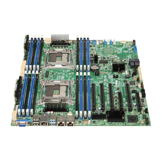
Intel® Server Board S2600CW Overview Intel® Server Board S2600CW Overview The Intel® Server Board S2600CW is a monolithic printed circuit board (PCB) with features designed to support the pedestal server markets. This server board is designed to support the Intel® Xeon® processor E5-2600 v3 and Intel® Xeon® processor E5-2600 v4 product families. - Page 18 Support for Intel® Remote Management Module 4 solutions Intel® Light-Guided Diagnostics on field replaceable units Support for Intel® System Management Software Support for Intel® Intelligent Power Node Manager (PMBus*-compliant power supply needed) Security Intel® TPM – AXXTPME5 (Accessory Option) Form Factor SSI EEB (12”x13”)
-
Page 19: Server Board Layout
Intel® Server Board S2600CW Family TPS Intel® Server Board S2600CW Overview Server Board Layout The following diagram shows the board layout for S2600CW2SR and S2600CWTSR with on-board SAS controller. Figure 1. Intel® Server Board S2600CW2SR and S2600CWTSR Revision 2.4... -
Page 20: Figure 2. Intel Server Board S2600Cw2R And S2600Cwtr
Intel® Server Board S2600CW Overview Intel® Server Board S2600CW Family TPS The following diagram shows the board layout for S2600CW2R and S2600CWTR without on-board SAS controller. Figure 2. Intel® Server Board S2600CW2R and S2600CWTR Revision 2.4... -
Page 21: Server Board Connector And Component Layout
Intel® Server Board S2600CW Family TPS Intel® Server Board S2600CW Overview 2.2.1 Server Board Connector and Component Layout The following figure shows the layout of the server board and the location of each connector and major component except jumpers. The locations of jumpers can be found in Chapter 8. -
Page 22: Server Board Mechanical Drawings
Intel® Server Board S2600CW Overview Intel® Server Board S2600CW Family TPS 2.2.2 Server Board Mechanical Drawings Figure 4. Mounting Hole Locations (1 of 2) Revision 2.4... -
Page 23: Figure 5. Mounting Hole Locations (2 Of 2)
Intel® Server Board S2600CW Family TPS Intel® Server Board S2600CW Overview Figure 5. Mounting Hole Locations (2 of 2) Revision 2.4... -
Page 24: Figure 6. Major Connector Pin-1 Locations (1 Of 2)
Intel® Server Board S2600CW Overview Intel® Server Board S2600CW Family TPS Figure 6. Major Connector Pin-1 Locations (1 of 2) Revision 2.4... -
Page 25: Figure 7. Major Connector Pin-1 Locations (2 Of 2)
Intel® Server Board S2600CW Family TPS Intel® Server Board S2600CW Overview Figure 7. Major Connector Pin-1 Locations (2 of 2) Revision 2.4... -
Page 26: Figure 8. Primary Side Card-Side Keep-Out Zone
Intel® Server Board S2600CW Overview Intel® Server Board S2600CW Family TPS Figure 8. Primary Side Card-Side Keep-out Zone Revision 2.4... -
Page 27: Figure 9. Second Side Keep-Out Zone
Intel® Server Board S2600CW Family TPS Intel® Server Board S2600CW Overview Figure 9. Second Side Keep-out Zone Revision 2.4... -
Page 28: Server Board Rear I/O Layout
The following drawing shows the layout of the rear I/O components for the server boards. Callout Description Callout Description Video USB 2.0 Dedicated Management NIC (DMN) USB 3.0 NIC1 NIC2 Diagnostic LEDs ID LED System Status LED Figure 10. Rear I/O Layout of Intel® Server Board S2600CW Revision 2.4... -
Page 29: Intel® Server Board S2600Cw Functional Architecture
Intel® Server Board S2600CW Functional Architecture The architecture and design of the Intel® Server Board S2600CW is based on the Intel® Xeon® E5-2600 v3 and v4 processors and the Intel® C612 chipset. This chapter provides a high-level description of the functionality associated with each chipset component and the architectural blocks that make up the server boards. -
Page 30: Processor Support
Processor Support The server board includes two Socket-R3 (LGA2011-3) processor sockets and can support two processors from the Intel® Xeon® processor E5-2600 v3 or v4 product families with a Thermal Design Power (TDP) of up to 145W. Previous generation Intel® Xeon® processors are not supported on the Intel® Server Boards described in this document. -
Page 31: Processor Population Rules
Processor Population Rules Note: Although the server board does support dual-processor configurations consisting of different processors that meet the defined criteria below, Intel does not perform validation testing of these configurations. For optimal system performance in dual-processor configurations, Intel recommends that identical processors be installed. -
Page 32: Table 2. Mixed Processor Configurations
The following table describes mixed processor conditions and recommended actions for all Intel® Server Boards and Intel® Server Systems designed around the Intel® Xeon® processor E5-2600 v3 and v4 product families and Intel® C612 chipset product family architecture. The errors fall into one of the following three categories: Fatal: If the system can boot, it pauses at a blank screen with the text “Unrecoverable... - Page 33 Intel® Server Board S2600CW Family TPS Intel® Server Board S2600CW Functional Architecture Error Severity System Action Processor model not Fatal The BIOS detects the error condition and responds as follows: Identical Logs the POST Error Code into the SEL. ...
-
Page 34: Processor Functions Overview
Controller (IMC), and Integrated IO Module (IIO). In addition, each processor package includes two Intel® QuickPath Interconnect point-to-point links capable of up to 9.6 GT/s, up to 40 lanes of Gen 3 PCI Express* links capable of 8.0 GT/s, and 4 lanes of DMI2/PCI Express* Gen 2 interface with a peak transfer rate of 5.0 GT/s. -
Page 35: Intel® Virtualization Technology (Intel® Vt) For Intel® 64 And Ia-32 Intel® Architecture (Intel® Vt-X)
Intel® Virtualization Technology for Directed I/O (Intel® VT-d) A general requirement for I/O virtualization models is the ability to isolate and restrict device accesses to the resources owned by the partition managing the device. Intel® VT for Directed I/O provides VMM software with the following capabilities:... -
Page 36: Intel® Trusted Execution Technology For Servers (Intel® Txt)
Intel® TXT defines platform-level enhancements that provide the building blocks for creating trusted platforms. The Intel® TXT platform helps to provide the authenticity of the controlling environment so that those wishing to rely on the platform can make an appropriate trust decision. -
Page 37: Enhanced Intel Speedstep® Technology
Intel® Node Manager 3.0 enables the PTAS-CUPS (Power Thermal Aware Scheduling – Compute Usage Per Second) feature of the Intel® Server Platform Services 3.0 Intel® ME FW. This is in essence a grouping of separate platform functionalities that provide Power, Thermal, and Utilization data that together offer an accurate, real time characterization of server workload. -
Page 38: Intel® Secure Key
Intel® Server Board S2600CW Functional Architecture Intel® Server Board S2600CW Family TPS This PTAS-CUPS data can then be used in conjunction with the Intel® Server Platform Services 3.0 Intel® Node Manager power monitoring/controls and a remote management application (such as the Intel® Data Center Manager [Intel® DCM]) to create a dynamic, automated, closed-loop data center management and monitoring system. -
Page 39: Supported Memory
Multi-rank level memory sparing Failed DIMM isolation 3.3.1 Supported Memory Table 3. DDR4 RDIMM & LRDIMM Support with Intel Xeon E5-2600 V3 Speed (MT/s) and Voltage Validated by Slot per Channel (SPC) and DIMM Per Channel Ranks Per Memory Capacity Per... -
Page 40: Memory Population Rules
Each installed processor provides four channels of memory. On the Intel Server Board ® S2600CW each memory channel supports two memory slots, for a total possible 16 DIMMs installed. System memory is organized into physical slots on DDR4 memory channels that ... -
Page 41: Figure 15. Intel Server Board S2600Cw Dimm Slot Layout
Channel C Channel D Figure 15. Intel ® Server Board S2600CW DIMM Slot Layout The following are generic DIMM population requirements that generally apply to the Intel ® Server Board S2600CW. All DIMMs must be DDR4 DIMMs. Mixing of LRDIMM with any other DIMM type is not allowed per platform. -
Page 42: Effects Of Memory Configuration On Memory Sizing
Mixing of DDR4 operating frequencies is not validated within a socket or across sockets by Intel. If DIMMs with different frequencies are mixed, all DIMMs will run at the common lowest frequency. A maximum of 8 logical ranks (ranks seen by the host) per channel is allowed. -
Page 43: Publishing System Memory
Intel® Server Board S2600CW Family TPS Intel® Server Board S2600CW Functional Architecture 3.3.4 Publishing System Memory There are a number of different situations in which the memory size and/or configuration are displayed. Most of these displays differ in one way or another, so the same memory configuration may appear to display differently, depending on when and where the display occurs. -
Page 44: 3.3.6 Memory Initialization
Intel® Server Board S2600CW Functional Architecture Intel® Server Board S2600CW Family TPS Memory Disable and Map out for FRB: Allows memory initialization and booting to the OS even when memory fault occurs. Data Scrambling with Command and Address: Scrambles the data with address and ... - Page 45 Intel® Server Board S2600CW Family TPS Intel® Server Board S2600CW Functional Architecture There are several errors which can be detected in different phases of initialization. During early POST, before system memory is available, serious errors that would prevent a system boot with data integrity will cause a System Halt with a beep code and a memory error code to be displayed via the POST Code Diagnostic LEDs.
- Page 46 Intel® Server Board S2600CW Functional Architecture Intel® Server Board S2600CW Family TPS Potential Error Cases: Invalid DIMM (type, organization, speed, size) – If a DIMM is found that is not a type supported by the system, the following error will be generated: POST Error Code 8501 “DIMM Population Error”, and a “Population Error”...
- Page 47 Intel® Server Board S2600CW Family TPS Intel® Server Board S2600CW Functional Architecture 3.3.6.4 Thermal (CLTT) and Power Throttling Potential Error Cases: CLTT Structure Error – The CLTT initialization fails due to an error in the data structure passed in by the BIOS. This results in a Fatal Error Halt 0xEF.
-
Page 48: System Io
Management Controller. 3.4.1 PCI Express* Support The integrated I/O module incorporates the PCI Express* interface and supports up to 40 lanes of PCI Express. The Intel® Server Board S2600CW supports six PCIe slots from two processors and PCH: From PCH: ... -
Page 49: Pcie Enumeration And Allocation
The BIOS automatically assigns IRQs to devices in the system for legacy compatibility. A method is not provided to manually configure the IRQs for devices. The following table shows the PCI layout for the Intel ® Server Board S2600CW. -
Page 50: Pcie Non-Transparent Bridge (Ntb)
The PCI Express Port 3A of Intel® Xeon® Processor E5-2600 Product Families can be configured to be a transparent bridge or an NTB with x4/x8/x16 link width and Gen1/Gen2/Gen3 link speed. -
Page 51: Pcie Ssd Support
port on the first system is connected to the NTB port of the second system. It is not necessary for the first system to be an Intel® Xeon® Processor E5-2600 Product Families system. Note: When NTB is enabled, Spread Spectrum Clocking (SSC) is required to be disabled at each NTB link. -
Page 52: Serial Ata (Sata) Support
3.4.5 Serial ATA (SATA) Support The Intel® C612 Series chipset provides the server board with support for up to ten Serial ATA (SATA) ports from two integrated controllers identified as SATA and sSATA. The Intel® Server Board S2600CW family on-board SATA connectors include: Two 7-pin single-port SATA connectors labeled “SATA-4”... -
Page 53: M.2/Ngff Support
can be used at the same time when M.2/NGFF device is used. In order to support full performance from Intel S3500 M.2 device, please use “Performance Mode” in Intel server BIOS setup options to meet thermal requirement. Using “Acoustic Mode”... -
Page 54: Embedded Sata Raid Support
Embedded SATA RAID Support The Intel® Server Board S2600CW2R/S2600CWTR has embedded support for two SATA SW RAID options: Intel® Rapid Storage Technology (RSTe) 4.0 Intel® Embedded Server RAID Technology 2 (ESRT2) based on LSI* MegaRAID SW RAID technology Revision 2.4... - Page 55 Note: RAID configurations cannot span across the two embedded AHCI SATA controllers. By using Intel® RSTe, there is no loss of PCI resources (request/grant pair) or add-in card slot. Intel® RSTe functionality requires the following: The SW-RAID option must be enabled in <F2> BIOS Setup ...
- Page 56 Intel® Server Board S2600CW Functional Architecture Intel® Server Board S2600CW Family TPS select recovery options when problems occur. The user interface can be accessed by hitting the <CTRL-I > keys during system POST. Providing boot support when using a RAID volume as a boot disk. It does this by ...
-
Page 57: Serial Attached Scsi (Sas) Support
3.4.9 Serial Attached SCSI (SAS) Support The Intel® Server Board S2600CW2SR/S2600CWTSR supports a Gen3 12G SAS IO Controller with LSISAS3008 (S2600CW2R/S2600CWTR does not support this). The 8-port SAS (12G) or SATA (6G) will connect to a 1x2 Right Angle (RA) mini-SAS HD connector and be used for Hot Swap Backplane (HSBP) connectivity. -
Page 58: Integrated Megaraid Support
Intel® Server Board S2600CW Functional Architecture Intel® Server Board S2600CW Family TPS 3.4.10 Integrated MegaRAID Support Integrated MegaRaid RAID (IMR) (RAID 0/1/10) support is included with based LSISAS3008 functionality. Integrated MegaRaid (IMR) (RAID 5) upgrade is supported through installation of an activation key. -
Page 59: Usb Support
3.4.11 USB Support The Intel® C612 Series chipset has up to two Enhanced Host Controller Interface (EHCI) host controllers that support USB high-speed signaling. The Intel® C612 Series chipset supports up to 14 USB 2.0 ports of which up to six can be used as USB3.0 ports. -
Page 60: Graphics Controller And Video Support
Intel® Server Board S2600CW Functional Architecture Intel® Server Board S2600CW Family TPS 3.4.12 Graphics Controller and Video Support The integrated graphics controller provides support for the following features as implemented on the server board: Integrated Graphics Core with 2D Hardware accelerator ... - Page 61 Intel® Server Board S2600CW Family TPS Intel® Server Board S2600CW Functional Architecture To provide for this, there is another PCI Configuration option to control “Legacy VGA Socket”. The rules for this are: This option appears only on boards which have the possibility of an add-in video ...
- Page 62 Intel® Server Board S2600CW Functional Architecture Intel® Server Board S2600CW Family TPS Case 4: Both onboard video and add-in video are active displays. But only onboard could be the active display during BIOS POST (Dual Monitor). Onboard Video = Enabled...
-
Page 63: Figure 16. Bios Setup Utility - Video Configuration Options
Intel® Server Board S2600CW Family TPS Intel® Server Board S2600CW Functional Architecture 3.4.12.2 Setting Video Configuration Options using the BIOS Setup Utility Advanced PCI Configuration Memory Mapped I/O above 4 GB Enabled / Disabled Memory Mapped I/O Size Auto/1G/2G/4G/8G/16G/32G/64G/128G/256G/512G/ 1024G... - Page 64 Intel® Server Board S2600CW Functional Architecture Intel® Server Board S2600CW Family TPS 2. Onboard Video Option Values: Enabled Disabled Help Text: On-board video controller. Warning: System video is completely disabled if this option is disabled and an add-in video adapter is not installed.
-
Page 65: Trusted Platform Module
MAC/PHY in a single low power package that supports dual-port 1G/10G Ethernet designs. The board also provides a 1G RJ45 Dedicated Management NIC port (DMN) for the Intel® Remote Management Module (RMM4 Lite). The DMN is active with or without the RMM4 Lite key installed. - Page 66 Integrated BMC LAN Channel MAC1 address – Assigned the NIC 1 MAC address +3 Intel® Remote Management Module (Intel® RMM) MAC address – Assigned the NIC 1 MAC address +4 The server board S2600CWTR/S2600CWTSR (X540) has the following MAC addresses...
-
Page 67: Table 7. External Rj45 Nic Port Led Definition
Intel® Server Board S2600CW Family TPS Intel® Server Board S2600CW Functional Architecture Each Ethernet port drives two LEDs located on each network interface connector. The LED at the left of the connector is the link/activity LED and indicates network connection when on, and transmit/receive activity when blinking. -
Page 68: System Security
System Security Intel® Server Board S2600CW Family TPS System Security The server board supports a variety of system security options designed to prevent unauthorized system access or tampering of server settings. System security options supported include: Password Protection Front Panel Lockout ... -
Page 69: Bios Password Protection
Intel® Server Board S2600CW Family TPS System Security Table 8. Setup Utility – Security Configuration Screen Fields Setup Item Options Help Text Comments TPM State Enabled and Information only. Activated Shows the current TPM device Enabled and state. Deactivated A disabled TPM device will not... - Page 70 System Security Intel® Server Board S2600CW Family TPS The Administrator and User passwords must be different from each other. An error message will be displayed if there is an attempt to enter the same password for one as for the other.
-
Page 71: Trusted Platform Module (Tpm) Support
Intel® Server Board S2600CW Family TPS System Security Trusted Platform Module (TPM) Support The Trusted Platform Module (TPM) option is a hardware-based security device that addresses the growing concern on boot process integrity and offers better data protection. TPM protects the system start-up process by ensuring it is tamper-free before releasing system control to the operating system. -
Page 72: Physical Presence
Intel® Trusted Execution Technology The Intel® Xeon® Processor E5-4600/2600/2400/1600 v3 and v4 product families support Intel® Trusted Execution Technology (Intel® TXT), which is a robust security environment. Designed to help protect against software-based attacks, Intel® Trusted Execution Technology integrates new security features and capabilities into the processor, chipset, and other platform components. - Page 73 Technology compatible measured launched environment (MLE). The MLE could consist of a virtual machine monitor, an OS, or an application. In addition, Intel® Trusted Execution Technology requires the system to include a TPM v1.2, as defined by the Trusted Computing Group TPM PC Client Specifications, Revision 1.2.
-
Page 74: Intel® Server Board S2600Cw Platform Management
The Intel® Server System BMC Firmware External Product Specification (EPS) and the Intel® Server System BIOS External Product Specification (EPS) for Intel® Server Products based on the Intel® Xeon® processor E5-2600 v3 and v4 product families should be referenced for more in-depth and design level platform management information. -
Page 75: Non-Ipmi Features Overview
Intel® Server Board S2600CW Family TPS Intel® Server Board S2600CW Platform Management Sensor Data Record (SDR) repository device functionality: The BMC supports storage and access of system SDRs. Sensor device and sensor scanning/monitoring: The BMC provides IPMI management ... - Page 76 Intel® Server Board S2600CW Platform Management Intel® Server Board S2600CW Family TPS Power unit management: Support for power unit sensor. The BMC handles power-good dropout conditions. DIMM temperature monitoring: New sensors and improved acoustic management using closed-loop fan control algorithm taking into account DIMM temperature readings.
-
Page 77: Platform Management Features And Functions
Intel® Server Board S2600CW Family TPS Intel® Server Board S2600CW Platform Management Energy Star Server Support. Smart Ride Through (SmaRT) / Closed Loop System Throttling (CLST). Power Supply Cold Redundancy. Power Supply FW Update. Power Supply Compatibility Check. -
Page 78: System Initialization
Intel® Server Board S2600CW Platform Management Intel® Server Board S2600CW Family TPS State Supported Description Supported only on Workstation platforms. See appropriate Platform Specific Information for more information. Not supported. Soft off. The front panel buttons are not locked. ... -
Page 79: Watchdog Timer
Intel® Server Board S2600CW Family TPS Intel® Server Board S2600CW Platform Management the SEL, the last POST code generated during the previous boot attempt is written. FRB2 failure is not reflected in the processor status sensor value. The FRB2 failure does not affect the front panel LEDs. -
Page 80: Sensor Rearm Behavior
Intel® Server Board S2600CW Platform Management Intel® Server Board S2600CW Family TPS system and the availability of the physical sensor when in that state. For example, non- standby voltages are not monitored when the system is in S4 or S5 power state. -
Page 81: Bios Event-Only Sensors
Intel® Server Board S2600CW Family TPS Intel® Server Board S2600CW Platform Management present; and the associated SDR is configured to enable a de-assertion event for that condition. 5.3.3 BIOS Event-Only Sensors BIOS-owned discrete sensors are used for event generation only and are not accessible through IPMI sensor commands like the Get Sensor Reading command. -
Page 82: System Airflow Monitoring
5.3.9 System Airflow Monitoring The sensor is valid only for Intel server chassis. BMC provides an IPMI sensor to report the volumetric system airflow in CFM (cubic feet per minute). The airflow in CFM is calculated based on the system fan PWM values. The specific Pulse Width Modulation (PWM or PWMs) used to determine the CFM is SDR configurable. - Page 83 5.3.10.2 Processor DTS-Spec Margin Sensor(s) Intel® Server Systems supporting the Intel® Xeon® processor E5-2600 v3 and v4 product families incorporate a DTS based thermal spec. This allows a much more accurate control of the thermal solution and enables lower fan speeds and lower fan power consumption. The main usage of this sensor is as an input to the BMC’s fan control algorithms.
- Page 84 5.3.10.9 Exit Air Temperature Monitoring The sensor is only valid for Intel server chassis. BMC synthesizes a virtual sensor to approximate system exit air temperature for use in fan control. This is calculated based on the total power being consumed by the system and the total volumetric airflow provided by the system fans.
-
Page 85: Processor Sensors
MEMHOT# inputs in order to throttle the associated memory to effectively lower the temperature of the VRD feeding that memory. For Intel® Server Systems supporting the Intel® Xeon® processor E5-2600 v3 and v4 product families there are two memory VRD_HOT# signals per CPU slot. The BMC instantiates one discrete IPMI sensor for each memory VRD_HOT# signal. -
Page 86: Table 10. Processor Sensors
Intel® Server Board S2600CW Platform Management Intel® Server Board S2600CW Family TPS Table 10. Processor Sensors Sensor Name Per-Processor Description Socket Processor Status Processor presence and fault state Digital Thermal Sensor Relative temperature reading by means of PECI Processor VRD Over-Temperature... - Page 87 Intel® Server Board S2600CW Family TPS Intel® Server Board S2600CW Platform Management 5.3.11.2 Processor Population Fault (CPU Missing) Sensor The BMC supports a Processor Population Fault sensor. This is used to monitor for the condition in which processor slots are not populated as required by the platform HW to allow power-on of the system.
-
Page 88: Voltage Monitoring
ED2 – CATERR type 0: Unknown 1: CATERR 2: CPU Core Error (not supported on Intel® Server Systems supporting the Intel® Xeon® processor E5-2600 v3 and v4 product families) 3: MSID Mismatch ED3 – CPU bitmap that causes the system CATERR... -
Page 89: Fan Monitoring
Intel® Server Board S2600CW Family TPS Intel® Server Board S2600CW Platform Management 5.3.12.1 DIMM Voltage Sensors Some systems support either LVDDR (Low Voltage DDR) memory or regular (non-LVDDR) memory. During POST, the system BIOS detects which type of memory is installed and configures the hardware to deliver the correct voltage. - Page 90 5.3.13.5 Monitoring for “Fans Off” Scenario On Intel® Server Systems supporting the Intel® Xeon® processor E5-2600 v3 and v4 product families, it is likely that there will be situations where specific fans are turned off based on current system conditions. BMC Fan monitoring will comprehend this scenario and not log false failure events.
-
Page 91: Standard Fan Management
Intel® Server Board S2600CW Family TPS Intel® Server Board S2600CW Platform Management By default the fans-off feature will be disabled. There is a BMC command and BIOS setup option to enable/disable this feature. The SmaRT/CLST system feature will also momentarily gate power to all the system fans to reduce overall system power consumption in response to a power supply event (for example, to ride out an AC power glitch). - Page 92 Intel® Server Board S2600CW Platform Management Intel® Server Board S2600CW Family TPS 5.3.14.1 Hot-Swap Fans Hot-swap fans are supported. These fans can be removed and replaced while the system is powered on and operating. The BMC implements fan presence sensors for each hot-swappable fan.
- Page 93 Intel® Server Board S2600CW Family TPS Intel® Server Board S2600CW Platform Management OEM SDR records are used to configure which temperature sensors are associated with which fan control domains and the algorithmic relationship between the temperature and fan speed. Multiple OEM SDRs can reference or control the same fan control domain; and multiple OEM SDRs can reference the same temperature sensors.
-
Page 94: Figure 18. High-Level Fan Speed Control Process
Intel® Server Board S2600CW Platform Management Intel® Server Board S2600CW Family TPS SSB (Intel® C612 Series Chipset) temperature sensor On-board Ethernet controller temperature sensors (support for this is specific to the Ethernet controller being used) On-board SAS controller temperature sensors ... - Page 95 Memory controller estimates the DRAM temperature in between actual reads of the TSODs. Hybrid CLTT shall be used on all Intel® Server Systems supporting the Intel® Xeon® processors E5-2600 v3 or v4 product family that have DIMMs with thermal sensors. Therefore, the terms Dynamic-CLTT and Static-CLTT are really referring to this “hybrid”...
- Page 96 This section describes the system level control of the fans internal to the power supply over the PMBus*. Some, but not all Intel® Server Systems supporting the Intel® Xeon® processor E5- 2600 v3 and v4 product families will require that the power supplies be included in the system level fan speed control.
-
Page 97: Power Management Bus (Pmbus*)
This enables easier usage of the fan speed control to support Intel as well as third-party chassis and better support of ambient temperatures higher than 35°C. -
Page 98: Power Supply Dynamic Redundancy Sensor
Several sets of component fault LEDs are supported on the server board. See the figures for Intel® Light Guided Diagnostics. Some LEDs are owned by the BMC and some by the BIOS. The BMC owns control of the following FRU/fault LEDs: Fan fault LEDs –... -
Page 99: Nmi (Diagnostic Interrupt) Sensor
Intel® Server Board S2600CW Family TPS Intel® Server Board S2600CW Platform Management asserted. Fan tach sensors are manual re-arm sensors. Once the lower critical threshold is crossed, the LED remains lit until the sensor is rearmed. These sensors are rearmed at system DC power-on and system reset. -
Page 100: Add-In Module Presence Sensor
Intel® Server Board S2600CW Platform Management Intel® Server Board S2600CW Family TPS The LAN Leash Lost offset asserts when one of the two BMC LAN channels loses a previously established link. It de-asserts when at least one LAN channel has a new link established after the previous assertion. - Page 101 Embedded Platform Debug feature – Allow the user to initiate a “debug dump” to a file that can be sent to Intel for debug purposes. Virtual Front Panel. The Virtual Front Panel provides the same functionality as the local ...
-
Page 102: Advanced Management Feature Support (Rmm4 Lite)
numbers used for SMASH, http, https, KVM, secure KVM, remote media, and secure remote media. For additional information, reference the Intel® Remote Management Module 4 and Integrated BMC Web Console Users Guide. Advanced Management Feature Support (RMM4 Lite) The integrated baseboard management controller has support for advanced management features which are enabled when an optional Intel ®... - Page 103 RMM4 Lite key is installed at the following location. ® Figure 19. Intel® RMM4 Lite Activation Key Location The server board includes a dedicated 1GbE RJ45 Management Port. The management port is active with or without the RMM4 Lite key installed.
-
Page 104: Keyboard, Video, Mouse (Kvm) Redirection
Intel® Server Board S2600CW Platform Management Intel® Server Board S2600CW Family TPS Key Features of the RMM4 add-on are: KVM redirection from either the dedicated management NIC or the server board NICs used for management traffic, up to two KVM sessions. -
Page 105: Remote Console
Intel® Server Board S2600CW Family TPS Intel® Server Board S2600CW Platform Management 640x480 at 60Hz, 72Hz, 75Hz, 85Hz, 100Hz 800x600 at 60Hz, 72Hz, 75Hz, 85Hz 1024x768 at 60Hz, 72Hz, 75Hz, 85Hz 1280x960 at 60Hz 1280x1024 at 60Hz ... -
Page 106: Security
Intel® Server Board S2600CW Platform Management Intel® Server Board S2600CW Family TPS 5.5.4 Security The KVM redirection feature supports multiple encryption algorithms, including RC4 and AES. The actual algorithm that is used is negotiated with the client based on the client’s capabilities. - Page 107 Intel® Server Board S2600CW Family TPS Intel® Server Board S2600CW Platform Management Media redirection supports redirection for both a virtual CD device and a virtual Floppy/USB device concurrently. The CD device may be either a local CD drive or else an ISO image file;...
- Page 108 Intel® Server Board S2600CW Platform Management Intel® Server Board S2600CW Family TPS Revision 2.4...
-
Page 109: Intel® Intelligent Power Node Manager (Nm) Support Overview
Intel® Server Board S2600CW Family TPS Intel® Intelligent Power Node Manager (NM) Support Overview Intel® Intelligent Power Node Manager (NM) Support Overview Power management deals with requirements to manage processor power consumption and manage power at the platform level to meet critical business needs. Node Manager (NM) is a platform resident technology that enforces power capping and thermal-triggered power capping policies for the platform. -
Page 110: Me System Management Bus (Smbus*) Interface
The Management Engine has access to the “Host SMBus*”. PECI 3.0 The BMC owns the PECI bus for all Intel server implementations and acts as a proxy for the ME when necessary. NM “Discovery” OEM SDR An NM “discovery” OEM SDR must be loaded into the BMC’s SDR repository if and only if the NM feature is supported on that product. -
Page 111: Dependencies On Pmbus*-Compliant Power Supply Support
Intel® Server Board S2600CW Family TPS Intel® Intelligent Power Node Manager (NM) Support Overview System power control modes include: SmaRT: Low AC input voltage event; results in a one-time momentary throttle for each event to the maximum throttle state. -
Page 112: Intel® Server Board S2600Cw Connector/Header Locations And Pin-Outs
Intel® Server Board S2600CW Connector/Header Locations and Pin-outs Intel® Server Board S2600CW Family TPS Intel® Server Board S2600CW Connector/Header Locations and Pin-outs Power Connectors 7.1.1 Main Power Connector Main server board power is supplied by one 12-pin power connector. The connector is labeled as “MAIN PWR”... -
Page 113: Front Panel Header And Connectors
Intel® Server Board S2600CW Family TPS Intel® Server Board S2600CW Connector/Header Locations and Pin-outs Signal Name Signal Name P12V3B P12V3B Front Panel Header and Connectors The server board includes several connectors that provide various possible front panel options. This section provides a functional description and pin-out for each connector. -
Page 114: On-Board Storage Connectors
Intel® Server Board S2600CW Connector/Header Locations and Pin-outs Intel® Server Board S2600CW Family TPS Table 18. Front Panel USB 3.0 Connector Pin-out Signal Name Signal Name P5V_AUX_USB_FP_USB3 USB3_01_FB_RX_DN P5V_AUX_USB_FP_USB3 USB3_01_FB_RX_DP USB3_00_FB_RX_DN USB3_00_FB_RX_DP USB3_01_FB_TX_DN USB3_01_FB_TX_DP USB3_00_FB_TX_DN USB3_00_FB_TX_DP USB2_13_FB_DN USB2_13_FB_DP USB2_8_FB_DN TP_FM_OC5_FP_R_N... -
Page 115: Sas Connectors
Intel® Server Board S2600CW Family TPS Intel® Server Board S2600CW Connector/Header Locations and Pin-outs Signal Name Signal Name PU_DATAIN1_SAS1 PU_DATAIN1_SAS0 SGPIO_SSATA_CLOCK_R1 SGPIO_SATA_CLOCK_R1 SGPIO_SSATA_LOAD_R1 SGPIO_SATA_LOAD_R1 PD_SAS1_CONTROLLER_TYPE PD_SAS0_CONTROLLER_TYPE 7.3.2 SAS Connectors The server boards S2600CW2SR and S2600CWTSR include two mini-SAS HD connectors supporting up to SAS 12Gbps transfer rates. -
Page 116: Internal Type-A Usb Connector
Intel® Server Board S2600CW Connector/Header Locations and Pin-outs Intel® Server Board S2600CW Family TPS Table 23. HDD LED Header Pin-out Signal Name Signal Name LED_HDD_ACT_N 7.3.5 Internal Type-A USB Connector The server board includes one internal Type-A USB connector. The following table provides the pin-out for this connector. -
Page 117: Management And Security Connectors
Intel® Server Board S2600CW Family TPS Intel® Server Board S2600CW Connector/Header Locations and Pin-outs Signal Name Signal Name Reserved Reserved SATA-A+ SATA-A- SATA-B- SATA-B+ DEVSLP(1)(0/3.3v) 3.3v 3.3v 3.3v 3.3v DAS/DSS#(O)(OD) 3.3v 3.3v Management and Security Connectors 7.4.1 RMM4 Lite Connector A 7-pin Intel ®... -
Page 118: Tpm Connector
Intel® Server Board S2600CW Connector/Header Locations and Pin-outs Intel® Server Board S2600CW Family TPS Table 27. RMM4 Lite Connector Pin-out Signal Name Signal Name P3V3_AUX CS_N 7.4.2 TPM Connector Table 28. TPM Connector Pin-out Signal Name Signal Name LPC_LAD<1> LPC_LAD<0>... -
Page 119: Ipmb Connector
Intel® Server Board S2600CW Family TPS Intel® Server Board S2600CW Connector/Header Locations and Pin-outs 7.4.5 IPMB Connector Table 31. IPMB Connector Pin-out Signal Name SMB_IPMB_5VSTBY_DATA SMB_IPMB_5VSTBY_CLK P5V_STBY FAN Connectors The server board provides support for nine fans. Seven of them are system cooling fans, and two of them are CPU fans. -
Page 120: Serial Port And Video Connectors
Intel® Server Board S2600CW Connector/Header Locations and Pin-outs Intel® Server Board S2600CW Family TPS Table 34. CPU FAN Connector Pin-out Signal Name TACH Serial Port and Video Connectors 7.6.1 Serial Port Connector The server board includes one internal DH-10 serial port connector. -
Page 121: Pcie Riser Slot
VLSI and power delivery components that need adequate airflow to cool. Intel’s own chassis are designed and tested to meet the intended thermal requirements of these components when the fully integrated system is used together. It is the responsibility of... - Page 122 Intel® Server Board S2600CW Connector/Header Locations and Pin-outs Intel® Server Board S2600CW Family TPS FM_THROTLE_SLOT6_N (RSVD) REFCLKP_1 REFCLKN_1 PETP0 PETN0 PERP0 PERN0 MUX_RST_N (PRSNT2_N) P3V3 (RSVD) PETP1 PETN1 PERP1 PERN1 PETP2 PETN2 PERP2 PERN2 PETP3 PETN3 PERP3 PERN3 P3V3 (RSVD) PD via 4.75Kohm (PRNST2_N)
- Page 123 Intel® Server Board S2600CW Family TPS Intel® Server Board S2600CW Connector/Header Locations and Pin-outs PETN8 PERP8 PERN8 PETP9 PETN9 PERP9 PERN9 PETP10 PETN10 PERP10 PERN10 PETP11 PETN11 PERP11 PERN11 PETP12 PETN12 PERP12 PERN12 PETP13 PETN13 PERP13 PERN13 PETP14 PETN14 PERP14...
- Page 124 Intel® Server Board S2600CW Connector/Header Locations and Pin-outs Intel® Server Board S2600CW Family TPS • Reuse Pin A7 as SAS_MODULE_ENABLE. This change applies to standard PCIe slot as well • Reuse Pin B17 as MUX_RST_N. • Reuse Pin B48/A50/B31 as LINK_WIDTH_ID.
-
Page 125: Intel Server Board S2600Cw Jumper Blocks
Intel® Server Board S2600CW Family TPS Intel® Server Board S2600CW Jumper Blocks Intel Server Board S2600CW Jumper Blocks ® The server boards have several 3-pin jumper blocks that you can use to configure, protect, or recover specific features of the server boards. -
Page 126: Bios Default And Password Reset Usage Procedure
Intel® Server Board S2600CW Jumper Blocks Intel® Server Board S2600CW Family TPS Jumper Name Pins System Results BMC Force BMC Firmware Force Update Mode – Disabled (Default) Update BMC Firmware Force Update Mode – Enabled Password Clear These pins should have a jumper in place for normal system operation. (Default) To clear administrator and user passwords, power on the system with pins 2-3 connected. -
Page 127: Integrated Bmc Force Update Procedure
Intel® Server Board S2600CW Family TPS Intel® Server Board S2600CW Jumper Blocks jumper, passwords can only be set or cleared by changing them explicitly in BIOS Setup or by similar means. No method of resetting BIOS configuration settings to default values will affect either the Administrator or User passwords. -
Page 128: Me Force Update Jumper
Intel® Server Board S2600CW Jumper Blocks Intel® Server Board S2600CW Family TPS 6. Perform the Integrated BMC firmware update procedure as documented in the README.TXT file that is included in the given Integrated BMC firmware update package. After successful completion of the firmware update process, the firmware update utility may generate an error stating that the Integrated BMC is still in update mode. -
Page 129: Bios Recovery Jumper
BIOS update instructions that are included with System Update Packages (SUP) downloaded from Intel’s download center web site. This jumper is used when the system BIOS has become corrupted and is non-functional, requiring a new BIOS image to be loaded on to the server board. -
Page 130: Intel Light Guided Diagnostics
Intel® Light Guided Diagnostics Intel® Server Board S2600CW Family TPS Intel Light Guided Diagnostics ® Both server boards have several onboard diagnostic LEDs to assist in troubleshooting board- level issues. This section provides a description of the location and function of each LED on the server boards. -
Page 131: Fan Fault Leds
Intel® Server Board S2600CW Family TPS Intel® Light Guided Diagnostics Fan Fault LEDs Fan fault LEDs are present for the two CPU fans. The fan fault LEDs illuminate when the corresponding fan has fault. Figure 23. Fan Fault LED’s Location... -
Page 132: Dimm Fault Leds
Intel® Light Guided Diagnostics Intel® Server Board S2600CW Family TPS DIMM Fault LEDs The server board provides memory fault LED for each DIMM socket. These LEDs are located as shown in the following figure. The DIMM fault LED illuminates when the corresponding DIMM slot has memory installed and a memory error occurs. -
Page 133: System Id Led, System Status Led, And Post Code Diagnostic Leds
Intel® Server Board S2600CW Family TPS Intel® Light Guided Diagnostics System ID LED, System Status LED, and POST Code Diagnostic LEDs The server board provides LEDs for system ID, system status, and POST code. These LEDs are located in the rear I/O area of the server board as shown in the following figure. -
Page 134: System Status Led
Intel® Light Guided Diagnostics Intel® Server Board S2600CW Family TPS 9.4.2 System Status LED The bi-color (green/amber) System Status LED operates as follows. Table 38. System Status LED Color State Criticality Description Green Solid on Indicates that the System Status is “Healthy”. The system is not exhibiting any errors. -
Page 135: Post Code Diagnostic Leds
Intel® Server Board S2600CW Family TPS Intel® Light Guided Diagnostics Color State Criticality Description 4. Hard drive fault. 5. Power Unit Redundancy sensor – Insufficient resources offset (indicates not enough power supplies present). 6. In non-sparing and non-mirroring mode if the threshold of correctable errors is crossed within the window. -
Page 136: 10. Power Supply Specification Guidelines
Note: The power supply data provided in this section is for reference purposes only. It reflects Intel’s own DC power out requirements from a 750W power supply and the Power Distribution Board as an option used in an Intel Server Chassis. -
Page 137: Table 40. Dc Output Connector
Intel® Server Board S2600CW Family TPS Power Supply Specification Guidelines 10.2.1.1 DC Output Connector The power supply uses a card edge output connection for power and signal that is compatible with a 2x25 Power Card Edge connector (equivalent to 2x25 pin configuration of the FCI power card connector 10035388-102LF). -
Page 138: Table 41. Led Characteristics
Power Supply Specification Guidelines Intel® Server Board S2600CW Family TPS 10.2.1.3 LED Marking and Identification The power supply uses a bi-color LED: Amber and Green. Below are table showing the LED states for each power supply operating state and the LED’s wavelength characteristics. -
Page 139: Ac Input Requirements
Intel® Server Board S2600CW Family TPS Power Supply Specification Guidelines Texit Maximum exit air temperature °C Non-operating temperature range °C non-op Altitude Maximum operating altitude 3050 Notes: Under normal conditions, the exit air temperature shall be less than 65°C. 68°C is provided for absolute worst case conditions and is expected only to exist when the inlet ambient reaches 60°C. -
Page 140: Table 46. Ac Line Holdup Time
Power Supply Specification Guidelines Intel® Server Board S2600CW Family TPS 10.2.2.4 AC Line Dropout/Holdup An AC line dropout is defined as that when the AC input drops to 0VAC at any phase of the AC line for any length of time. During an AC dropout, the power supply meets dynamic voltage regulation requirements. -
Page 141: Efficiency
Intel® Server Board S2600CW Family TPS Power Supply Specification Guidelines Table 48. AC Line Surge Transient Performance AC Line Surge Duration Surge Operating AC Voltage Line Frequency Performance Criteria Continuous Nominal AC Voltages 50/60Hz No loss of function or performance 0 to ½... -
Page 142: Table 51. Voltage Regulation Limits
Power Supply Specification Guidelines Intel® Server Board S2600CW Family TPS 10.2.4.3 Voltage Regulation The power supply output voltages stay within the following voltage limits when operating at steady state and dynamic loading conditions. These limits include the peak-peak ripple/noise. These shall be measured at the output connectors. - Page 143 Intel® Server Board S2600CW Family TPS Power Supply Specification Guidelines The power supply is provided with a reliable protective earth ground. All secondary circuits is connected to protective earth ground. Resistance of the ground returns to chassis does not exceed 1.0 mΩ. This path may be used to carry DC current.
-
Page 144: Figure 27. Differential Noise Test Setup
Power Supply Specification Guidelines Intel® Server Board S2600CW Family TPS A 10µF tantalum capacitor in parallel with a 0.1µF ceramic capacitor is placed at the point of measurement. Table 54. Ripples and Noise +12V Main +12VSB 120mVp-p 120mVp-p The test setup shall be as shown below. -
Page 145: Protection Circuits
Intel® Server Board S2600CW Family TPS Power Supply Specification Guidelines Item Description Units Delay from PSON# active to output voltages pson_on_delay within regulation limits. Delay from PSON# deactivate to PWOK being pson_pwok de-asserted. Delay from output voltages within regulation pwok_on limits to PWOK asserted at turn on. -
Page 146: Control And Indicator Functions
Power Supply Specification Guidelines Intel® Server Board S2600CW Family TPS 10.2.5.1 Current Limit (OCP) The power supply has current limit to prevent the outputs from exceeding the values shown in table below. If the current limits are exceeded the power supply shuts down and latches-off. -
Page 147: Figure 29. Pson# Required Signal Characteristic
Intel® Server Board S2600CW Family TPS Power Supply Specification Guidelines 10.2.6.1 PSON# Input Signal The PSON# signal is required to remotely turn on/off the power supply. PSON# is an active low signal that turns on the +12V power rail. When this signal is not pulled low by the system, or left open, the outputs (except the +12VSB) turn off. -
Page 148: Table 59. Pwok Signal Characteristics
Power Supply Specification Guidelines Intel® Server Board S2600CW Family TPS Table 59. PWOK Signal Characteristics Signal Type Open collector/drain output from power supply. Pull-up to VSB located in the power supply. PWOK = High Power OK PWOK = Low Power Not OK Logic level low voltage, Isink=400uA 0.4V... -
Page 149: Thermal Clst
Intel® Server Board S2600CW Family TPS Power Supply Specification Guidelines 10.2.7 Thermal CLST The power supply shall assert the SMBAlert signal when a temperature sensor crosses a warning threshold. Refer to the Intel Common Hardware and Firmware Requirements for CRPS ®... -
Page 150: Higer Power Common Redundant Power Distribution Board (Pdb)
Power Supply Specification Guidelines Intel® Server Board S2600CW Family TPS 10.3 Higer Power Common Redundant Power Distribution Board (PDB) The Power Distribution Board (PDB) for the Intel Server Chassis P4000M supports the ® Common Redundant power supply in a 1+1 redundant configuration. The PDB is designed to plug directly to the output connector of the PS and it contains 3 DC/DC power converters to produce other required voltages: +3.3VDC, +5VDC, and 5V standby along with additional over... -
Page 151: Dc Output Specification
Intel® Server Board S2600CW Family TPS Power Supply Specification Guidelines The amount of cooling airflow that will be available to the DC/DC converters is to be no less than 1.2M/s. Figure 31. Airflow Diagram 10.3.1.2 DC/DC Converter Cooling The DC/DC converters on the power distribution board are in series with the airflow path with the power supplies. -
Page 152: Table 62. Input Connector And Pin Assignment
Power Supply Specification Guidelines Intel® Server Board S2600CW Family TPS Table 62. Input Connector and Pin Assignment Name Name +12V +12V +12V +12V +12V +12V +12V +12V +12V +12V +12V +12V +12V +12V +12V +12V +12V +12V PMBus* SDA A0 (SMBus* address) -
Page 153: Table 64. P1 Baseboard Power Connector
Intel® Server Board S2600CW Family TPS Power Supply Specification Guidelines From Length, To connector No of Description pins Power Supply cover exit hole SATA peripheral power connector for 5.25” Extension from P5 SATA peripheral power connector for 5.25” Extension from P6 Peripheral Power Connector for 5.25”/HSBP Power... -
Page 154: Table 65. P0 Processor Power Connector
Power Supply Specification Guidelines Intel® Server Board S2600CW Family TPS 10.3.2.2.2 Processor#0 Power Connector (P2) Connector housing: 8-pin Molex* 39-01-2080 or equivalent Contact: Molex* Mini-Fit, HCS Plus, Female, Crimp 44476 or equivalent Table 65. P0 Processor Power Connector... -
Page 155: Table 68. P12 12V Connectors
Intel® Server Board S2600CW Family TPS Power Supply Specification Guidelines Table 68. P12 12V Connectors Signal 18 AWG color Signal 18 AWG Color Black +12V1 Yellow Black +12V1 Yellow Table 69. P13-P16 12V Connectors Signal 18 AWG color Signal 18 AWG Color... -
Page 156: Table 73. Remote Sense Connection Points
Power Supply Specification Guidelines Intel® Server Board S2600CW Family TPS Signal 18 AWG Color +5VDC Black +12V2 Yellow 10.3.2.3 Grounding The ground of the pins of the PDB output connectors provides the power return path. The output connector ground pins is connected to safety ground (PDB enclosure). This grounding is well designed to ensure passing the maximum allowed Common Mode Noise levels. -
Page 157: Table 76. Hard Drive 12V Rail Configuration Options
Intel® Server Board S2600CW Family TPS Power Supply Specification Guidelines Memor Memor Total Min Nomin peripherals Curre 17.8 10.5 A 17.8 10.5 A 21. 91 A 91 95.5 76 A 76 18.0 A 18 A 18 Note: +12V current to PCIe slots may be supplied from four different connectors. 12V1 on P2, 12V2 on P3, 12V3 on P1, and 12V3 on P12. -
Page 158: Table 78. 5Vsb Loading
Power Supply Specification Guidelines Intel® Server Board S2600CW Family TPS +12VDC Input DC/DC Converters +3.3V Converter +5V Converter -12V Converter Max Output Power 3.3V x25A =82.5W 5V x25A =125W 12V x0.5A =6W 10.3.2.8 5VSB Loading There is also one DC/DC converter that converts the 12V standby into 5V standby. -
Page 159: Table 81. Capacitive Loading Conditions
Intel® Server Board S2600CW Family TPS Power Supply Specification Guidelines 10.3.2.11 DC/DC Converter Capacitive Loading The DC/DC converters are stable and meet all requirements with the following capacitive loading ranges. Minimum capacitive loading applies to static load only. Table 81. Capacitive Loading Conditions... -
Page 160: Figure 32. Differential Noise Test Setup
Power Supply Specification Guidelines Intel® Server Board S2600CW Family TPS LOAD MUST BE AC HOT ISOLATED FROM POWER SUPPLY LOAD THE GROUND OF RETURN AC NEUTRAL THE POWER 10uF SUPPLY .1uF AC GROUND GENERAL NOTES: LOAD THE OUTPUT WITH ITS MINIMUM LOAD CURRENT. -
Page 161: Protection Circuits
Intel® Server Board S2600CW Family TPS Power Supply Specification Guidelines 10.3.3 Protection Circuits The PDB shall shut down all the DC/DC converters on the PDB and the power supply (by PSON) if there is a fault condition on the PDB (OVP or OCP). If the PDB DC/DC converter latches-off due to a protection circuit tripping, an AC cycle OFF for 15sec min or a PSON# cycle HIGH for 1sec shall be able to reset the power supply and the PDB. -
Page 162: Pwok (Power Ok) Signal
Power Supply Specification Guidelines Intel® Server Board S2600CW Family TPS Output Voltage OVP Min (v) OVP Max (v) -12V -13.3 -15.5 +5VSB 10.3.4 PWOK (Power OK) Signal The PDB connects the PWOK signals from the power supply modules and the DC/DC converters to a common PWOK signal. -
Page 163: 11. Design And Environmental Specifications
Intel Corporation cannot be held responsible if components fail or the server board does not operate correctly when used outside any of its published operating or non-operating limits. -
Page 164: 11.2 Mtbf
Design and Environmental Specifications Intel® Server Board S2600CW Family TPS amount of airflow required for their specific application and environmental conditions. Intel Corporation cannot be held responsible, if components fail or the server board does not operate correctly when used outside any of its published operating or non-operating limits. -
Page 165: Appendix A: Integration And Usage Tips
Intel® Server Board S2600CW Family TPS Appendix A: Integration and Usage Tips Appendix A: Integration and Usage Tips When adding or removing components or peripherals from the server board, AC power must be removed. With AC power plugged into the server board, 5-V standby is still present even though the server board is powered off. -
Page 166: Appendix B: Compatible Intel Server Chassis
Appendix B: Compatible Intel® Server Chassis Intel® Server Board S2600CW Family TPS Appendix B: Compatible Intel Server Chassis ® The Intel ® Server Board S2600CW can be used inside the Intel ® Server Chassis P4000M family. Table 90. Compatible Intel ® Server Chassis Chassis Name... -
Page 167: Appendix C: Bmc Sensor Tables
Intel® Server Board S2600CW Family TPS Appendix C: BMC Sensor Tables Appendix C: BMC Sensor Tables This appendix lists the sensor identification numbers and information about the sensor type, name, supported thresholds, assertion and de-assertion information, and a brief description of the sensor purpose. - Page 168 Appendix C: BMC Sensor Tables Intel® Server Board S2600CW Family TPS readable. Readable offsets consist of the reading type offsets that do not generate events. Event Data Event data is the data that is included in an event message generated by the associated sensor.
-
Page 169: Table 91. Integrated Bmc Core Sensors
Intel® Server Board S2600CW Family TPS Appendix C: BMC Sensor Tables Note: All sensors listed below may not be present on all platforms. Check platform EPS section for platform applicability and platform chassis section for chassis specific sensors. Redundancy sensors are present only on systems with appropriate hardware to support redundancy (for instance, fan or power supply). - Page 170 Appendix C: BMC Sensor Tables Intel® Server Board S2600CW Family TPS Full Sensor Name Senso Platform Sensor Type Event/Rea Event Offset Contrib. To Assert Readab Event Rearm Stand- Applicabili ding Type Triggers System /De- (Sensor name in SDR) Data Status...
- Page 171 Intel® Server Board S2600CW Family TPS Appendix C: BMC Sensor Tables Full Sensor Name Senso Platform Sensor Type Event/Rea Event Offset Contrib. To Assert Readab Event Rearm Stand- Applicabili ding Type Triggers System /De- (Sensor name in SDR) Data Status...
- Page 172 Appendix C: BMC Sensor Tables Intel® Server Board S2600CW Family TPS Full Sensor Name Senso Platform Sensor Type Event/Rea Event Offset Contrib. To Assert Readab Event Rearm Stand- Applicabili ding Type Triggers System /De- (Sensor name in SDR) Data Status...
- Page 173 Intel® Server Board S2600CW Family TPS Appendix C: BMC Sensor Tables Full Sensor Name Senso Platform Sensor Type Event/Rea Event Offset Contrib. To Assert Readab Event Rearm Stand- Applicabili ding Type Triggers System /De- (Sensor name in SDR) Data Status...
- Page 174 Appendix C: BMC Sensor Tables Intel® Server Board S2600CW Family TPS Full Sensor Name Senso Platform Sensor Type Event/Rea Event Offset Contrib. To Assert Readab Event Rearm Stand- Applicabili ding Type Triggers System /De- (Sensor name in SDR) Data Status...
- Page 175 Intel® Server Board S2600CW Family TPS Appendix C: BMC Sensor Tables Full Sensor Name Senso Platform Sensor Type Event/Rea Event Offset Contrib. To Assert Readab Event Rearm Stand- Applicabili ding Type Triggers System /De- (Sensor name in SDR) Data Status...
- Page 176 Appendix C: BMC Sensor Tables Intel® Server Board S2600CW Family TPS Full Sensor Name Senso Platform Sensor Type Event/Rea Event Offset Contrib. To Assert Readab Event Rearm Stand- Applicabili ding Type Triggers System /De- (Sensor name in SDR) Data Status...
- Page 177 Intel® Server Board S2600CW Family TPS Appendix C: BMC Sensor Tables Full Sensor Name Senso Platform Sensor Type Event/Rea Event Offset Contrib. To Assert Readab Event Rearm Stand- Applicabili ding Type Triggers System /De- (Sensor name in SDR) Data Status...
- Page 178 Appendix C: BMC Sensor Tables Intel® Server Board S2600CW Family TPS Full Sensor Name Senso Platform Sensor Type Event/Rea Event Offset Contrib. To Assert Readab Event Rearm Stand- Applicabili ding Type Triggers System /De- (Sensor name in SDR) Data Status...
- Page 179 Intel® Server Board S2600CW Family TPS Appendix C: BMC Sensor Tables Full Sensor Name Senso Platform Sensor Type Event/Rea Event Offset Contrib. To Assert Readab Event Rearm Stand- Applicabili ding Type Triggers System /De- (Sensor name in SDR) Data Status...
- Page 180 Appendix C: BMC Sensor Tables Intel® Server Board S2600CW Family TPS Full Sensor Name Senso Platform Sensor Type Event/Rea Event Offset Contrib. To Assert Readab Event Rearm Stand- Applicabili ding Type Triggers System /De- (Sensor name in SDR) Data Status...
- Page 181 Intel® Server Board S2600CW Family TPS Appendix C: BMC Sensor Tables Full Sensor Name Senso Platform Sensor Type Event/Rea Event Offset Contrib. To Assert Readab Event Rearm Stand- Applicabili ding Type Triggers System /De- (Sensor name in SDR) Data Status...
- Page 182 Appendix C: BMC Sensor Tables Intel® Server Board S2600CW Family TPS Full Sensor Name Senso Platform Sensor Type Event/Rea Event Offset Contrib. To Assert Readab Event Rearm Stand- Applicabili ding Type Triggers System /De- (Sensor name in SDR) Data Status...
- Page 183 Intel® Server Board S2600CW Family TPS Appendix C: BMC Sensor Tables Full Sensor Name Senso Platform Sensor Type Event/Rea Event Offset Contrib. To Assert Readab Event Rearm Stand- Applicabili ding Type Triggers System /De- (Sensor name in SDR) Data Status...
- Page 184 Appendix C: BMC Sensor Tables Intel® Server Board S2600CW Family TPS Revision 2.4...
-
Page 185: Appendix D: Platform Specific Bmc Appendix
Intel® Server Board S2600CW Family TPS Appendix D: Platform Specific BMC Appendix Appendix D: Platform Specific BMC Appendix This is an addendum document to BMC Core EPS. This document describes platform and chassis specific information. Product ID Bytes 11:12 (product ID) of Get Device ID command response: 71h 00h IPMI Channel ID Assignments Below table provides the information of BMC channels’... - Page 186 Fan 4 Present (43h) System Fan 5 (34h) Fan 5 Present (44h) Hot-plug Fan Support Supported on Intel® Server Chassis P4000 Redundant (Union Peak Medium) only Fan Redundancy Support Supported on Intel® Server Chassis P4000 Redundant (Union Peak Medium) only Fan Domain Definition...
- Page 187 Intel® Server Board S2600CW Family TPS Appendix D: Platform Specific BMC Appendix Major Components Cooled Fans Chassis Fan Domain (Temperature sensor number) (Sensor number) P2 DTS Therm Mgn (84h) MIC 1 Margin (C4h) MIC 2 Margin (C5h) MIC 3 Margin (C6h)
- Page 188 Appendix D: Platform Specific BMC Appendix Intel® Server Board S2600CW Family TPS Major Components Cooled Fans Chassis Fan Domain (Temperature sensor number) (Sensor number) Exit Air Temp (2Eh) P1 DTS Therm Mgn (83h) P2 DTS Therm Mgn (84h) MIC 1 Margin (C4h)
- Page 189 Intel® Server Board S2600CW Family TPS Appendix D: Platform Specific BMC Appendix Major Components Cooled Fans Chassis Fan Domain (Temperature sensor number) (Sensor number) HSBP 1 Temp (29h) Exit Air Temp (2Eh) P1 DTS Therm Mgn (83h) P2 DTS Therm Mgn (84h)
-
Page 190: Appendix E: Post Code Diagnostic Led Decoder
Appendix E: POST Code Diagnostic LED Decoder Intel® Server Board S2600CW Family TPS Appendix E: POST Code Diagnostic LED Decoder During the system boot process, the BIOS executes a number of platform configuration processes, each of which is assigned a specific hex POST code number. As each configuration routine is started, the BIOS displays the POST code to the POST Code Diagnostic LEDs on the back edge of the server board. -
Page 191: Table 92. Post Progress Code Led Example
Intel® Server Board S2600CW Family TPS Appendix E: POST Code Diagnostic LED Decoder Table 92. POST Progress Code LED Example Upper Nibble AMBER LEDs Lower Nibble GREEN LEDs LEDs LED #7 LED #6 LED #5 LED #4 LED #3 LED #2... - Page 192 Appendix E: POST Code Diagnostic LED Decoder Intel® Server Board S2600CW Family TPS 0xAC Phy layer settings 0xAD Link Layer settings 0xAE Coherency settings 0xAF QPI initialization done 0x07 Early SB initialization during SEC phase 0x08 Early NB initialization during SEC phase...
- Page 193 Intel® Server Board S2600CW Family TPS Appendix E: POST Code Diagnostic LED Decoder 0x62 DXE Setup Init 0x63 DXE CPU Init 0x65 DXE CPU BSP Select 0x66 DXE CPU AP Init 0x68 DXE PCI Host Bridge Init 0x69 DXE NB Init...
- Page 194 Appendix E: POST Code Diagnostic LED Decoder Intel® Server Board S2600CW Family TPS 0x8C DXE USB detect 0x8D DXE USB enable 0x91 DXE IDE begin 0x92 DXE IDE reset 0x93 DXE IDE detect 0x94 DXE IDE enable 0x95 DXE SCSI begin...
- Page 195 Intel® Server Board S2600CW Family TPS Appendix E: POST Code Diagnostic LED Decoder S3 Resume 0x40 S3 Resume PEIM (S3 started) 0x41 S3 Resume PEIM (S3 boot script) 0x42 S3 Resume PEIM (S3 Video Repost) 0x43 S3 Resume PEIM (S3 OS wake)
-
Page 196: Table 94. Mrc Progress Codes
Appendix E: POST Code Diagnostic LED Decoder Intel® Server Board S2600CW Family TPS Table 94. MRC Progress Codes Progress Main Sequence Subsequences / Code subfunctions 0xB0 Detect DIMM population --n/a-- 0x B1 Set DDR4 frequency --n/a-- 0x B2 Gather remaining SPD data... -
Page 197: Table 95. Mrc Fatal Error Codes
02h = Memory DIMMs on all channels of all sockets are disabled due to hardware memtest error. • 03h = No memory installed. All channels are disabled. 0xE9 Memory is locked by Intel® Trusted Execution Technology and is inaccessible. 0xEA DDR4 Channel Training Error 01h = Error on read DQ/DQS (Data/Data Strobe) Init •... -
Page 198: Appendix F: Post Error Code
Processor core/thread count mismatch detected Fatal 0192 Processor cache size mismatch detected Fatal 0194 Processor family mismatch detected Fatal 0195 Processor Intel(R) QPI link frequencies unable to synchronize Fatal 0196 Processor model mismatch detected Fatal 0197 Processor frequencies unable to synchronize Fatal 5220... - Page 199 Intel® Server Board S2600CW Family TPS Appendix F: POST Error Code Error Code Error Message Response 8131 Processor 02 disabled Major 8132 Processor 03 disabled Major 8133 Processor 04 disabled Major 8160 Processor 01 unable to apply microcode update Major...
- Page 200 Appendix F: POST Error Code Intel® Server Board S2600CW Family TPS Error Code Error Message Response 852F DIMM_F1 failed test/initialization Major 8530 DIMM_F2 failed test/initialization Major 8531 DIMM_F3 failed test/initialization Major 8532 DIMM_G1 failed test/initialization Major 8533 DIMM_G2 failed test/initialization...
- Page 201 Intel® Server Board S2600CW Family TPS Appendix F: POST Error Code Error Code Error Message Response 8559 DIMM_I2 disabled Major 855A DIMM_I3 disabled Major 855B DIMM_J1 disabled Major 855C DIMM_J2 disabled Major 855D DIMM_J3 disabled Major 855E DIMM_K1 disabled Major...
- Page 202 Appendix F: POST Error Code Intel® Server Board S2600CW Family TPS Error Code Error Message Response 85C2 DIMM_L2 failed test/initialization Major 85C3 DIMM_L3 failed test/initialization Major 85C4 DIMM_M1 failed test/initialization Major 85C5 DIMM_M2 failed test/initialization Major 85C6 DIMM_M3 failed test/initialization...
-
Page 203: Table 97. Post Error Beep Codes
The Integrated BMC may generate beep codes upon detection of failure conditions. Beep codes are sounded each time the problem is discovered, such as on each power-up attempt, but are not sounded continuously. Codes that are common across all Intel Server Boards and ®... - Page 204 Appendix F: POST Error Code Intel® Server Board S2600CW Family TPS 1-5-2-4 MSID Mismatch. MSID Mismatch Sensor 1-5-4-2 Power fault: DC power is unexpectedly Power unit – power unit failure lost (power good dropout). offset 1-5-4-4 Power control fault (power good Power unit –...
-
Page 205: Appendix G: Statement Of Volatility
This Appendix describes the volatile and non-volatile components on the Intel ® Server Board S2600CW Product Family. It is not the intention of this document to include any components not directly on the listed Intel server boards, such as the chassis components, processors, memory, hard drives, or add-in cards. - Page 206 BMC: The server boards support an Intelligent Platform Management Interface (IPMI) 2.0 conformant baseboard management controller (BMC). The BMC provides health monitoring, alerting and remote power control capabilities for the Intel server board. ® The BMC does not have access to operating system level data.
-
Page 207: Glossary
Intel® Server Board S2600CW Family TPS Glossary Glossary This appendix contains important terms used in the preceding chapters. For ease of use, numeric entries are listed first (for example, 82460GX) with alpha entries following (for example, AGP 4x). Acronyms are then entered in their respective place, with non-acronyms following. - Page 208 Glossary Intel® Server Board S2600CW Family TPS Term Definition Input Buffer I/O Controller Hub ICMB Intelligent Chassis Management Bus IERR Internal Error I/O and Firmware Bridge INTR Interrupt Internet Protocol IPMB Intelligent Platform Management Bus IPMI Intelligent Platform Management Interface...
- Page 209 Intel® Server Board S2600CW Family TPS Glossary Term Definition PSMI Power Supply Management Interface Pulse-Width Modulation Random Access Memory RASUM Reliability, Availability, Serviceability, Usability, and Manageability RISC Reduced Instruction Set Computing Read Only Memory Real-Time Clock (Component of ICH peripheral chip on the server board)
-
Page 210: Reference Documents
http://www.acpi.info/. Intelligent Platform Management Bus Communications Protocol Specification, Version 1.0. 1998. Intel Corporation, Hewlett-Packard Company, NEC Corporation, Dell Computer Corporation. Intelligent Platform Management Interface Specification, Version 2.0. 2004. Intel Corporation, Hewlett-Packard Company, NEC Corporation, Dell Computer Corporation.
Need help?
Do you have a question about the S2600CW and is the answer not in the manual?
Questions and answers
How to clear S2600CW mother board BIOS password
To clear the BIOS password on an Intel S2600CW motherboard, use the Password Clear jumper. This will remove both the Administrator and User passwords. After clearing, passwords must be set again through the BIOS Setup utility to restore security. This is the only unconditional method to reset BIOS passwords.
This answer is automatically generated