Sign In
Upload
Manuals
Brands
Intel Manuals
Software
S3420GP
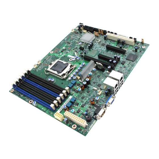
Intel S3420GP Server Board Manuals
Manuals and User Guides for Intel S3420GP Server Board. We have
4
Intel S3420GP Server Board manuals available for free PDF download: Software User's Manual, Specification, Manual, Installation Manual
Intel S3420GP Software User's Manual (204 pages)
Software User's Guide
Brand:
Intel
| Category:
Server
| Size: 9 MB
Table of Contents
Table of Contents
3
Chapter 1: Overview
15
Supported Hardware
15
Software
17
RAID Terminology
18
Fault Tolerance
18
Hot Spare
19
Enclosure Management
20
Performance
20
Disk Striping
21
Disk Spanning
21
Cpu Usage
21
Chapter 2: RAID Levels
23
Summary of RAID Levels
23
Selecting a RAID Level
24
RAID 0 - Data Striping
24
Figure 1. RAID 0 - Data Striping
24
Table 1. RAID 0 Overview
24
RAID 1 - Disk Mirroring/Disk Duplexing
25
RAID 5 - Data Striping with Striped Parity
25
Figure 2. RAID 1 - Disk Mirroring/Disk Duplexing
25
Table 2. RAID 1 Overview
25
RAID 6 - Distributed Parity and Disk Striping
26
Figure 3. RAID 5 - Data Striping with Striped Parity
26
Table 3. RAID 5 Overview
26
Table 4. RAID 6 Overview
26
Raid Ime
27
Figure 4. Example of Distributed Parity Across Two Blocks in a Stripe (RAID 6)
27
RAID 10 - Combination of RAID 1 and RAID 0
28
Figure 5. Integrated Mirroring Enhanced with Three Disks
28
Table 5. RAID 1E Overview
28
RAID 50 - Combination of RAID 5 and RAID 0
29
Figure 6. RAID 10 - Combination of RAID 1 and RAID 0
29
Table 6. RAID 10 Overview
29
RAID 60 - Combination of RAID 0 and RAID 6
30
Figure 7. RAID 50 - Combination of RAID 5 and RAID 0
30
Table 7. RAID 50 Overview
30
Table 8. RAID 60 Overview
31
Figure 8. RAID 60 Level Virtual Drive
32
RAID Configuration Strategies
33
Maximizing Fault Tolerance
33
Table 9. RAID Levels and Fault Tolerance
33
Maximizing Performance
34
Table 10. RAID Levels and Performance
34
Maximizing Storage Capacity
35
Table 11. RAID Levels and Capacity
36
RAID Availability
37
RAID Availability Concept
37
Spare Drives
37
Rebuilding
37
Drive in Foreign State
37
Copyback
38
Configuration Planning
38
Dimmer Switch Feature
39
Number of Physical Disks
39
Megaraid Fast Path
39
4K Sector Drive Support
39
Larger than 2TB Drive Support
40
Power Save Settings
40
Shield State
40
Array Purpose
41
Table 12. Factors to Consider for Array Configuration
41
Chapter 3: RAID Utilities
43
Intel Embedded Server RAID Technology 2 BIOS Configuration Utility
43
LSI MPT* SAS BIOS Configuration Utility
43
Intel RAID BIOS Console 2 Configuration Utility for Intelligent RAID
44
Intel RAID Web Console 2 Configuration and Monitoring Utility
45
Drive Hierarchy Within the RAID Firmware
46
Intel Intelligent RAID Controller Features
46
Enterprise Features
46
Fault Tolerant Features
47
Cache Options and Settings
48
Background Tasks
48
Error Handling
49
Audible Alarm
49
Chapter 4: Intel ® RAID Drivers
51
RAID Driver Installation for Microsoft Windows
51
Installation in a New Microsoft Windows* Operating System
51
Installation in an Existing Microsoft Windows* Operating System
52
RAID Driver Installation for Red Hat* Enterprise Linux
52
RAID Driver Installation for Suse* Linux
53
RAID Driver Installation for Novell Netware
53
Installation in a New Novell Netware* System
53
Installation in an Existing Novell Netware* System
54
RAID Driver Installation for Solaris* 10
54
Installation in a New Solaris* System
54
Installation in an Existing Solaris* System
54
Chapter 5: Intel ® Embedded Server RAID BIOS Configuration Utility
55
Creating, Adding or Modifying a Virtual Drive Configuration
56
Figure 9. Intel ® Embedded Server RAID BIOS Configuration Utility Screen
56
Raid Level
57
Stripe Size
57
Setting the Write Cache and Read Ahead Policies
58
Working with a Global Hot-Spare Drive
58
Adding a Hot-Spare Drive
59
Removing a Hot-Spare Drive
59
Rebuilding a Drive
59
Auto Rebuild and Auto Resume
59
Checking Data Consistency
60
Viewing and Changing Device Properties
60
Forcing a Drive Online or Offline
61
Configuring a Bootable Virtual Drive
61
Deleting (Clearing) a Storage Configuration
61
Chapter 6: Intel IT/IR RAID Configuration
63
IM and IME Configuration Overview
63
Features
63
Creating IM and IME Volumes
64
Creating an IM Volume
65
Figure 10. Adapter Properties Screen
65
Creating an IME Volume
66
Figure 11. Create New Array Screen
66
Creating a Second IM or IME Volume
67
Managing Hot Spares
67
Figure 12. Manage Array Screen
68
Other Configuration Tasks
69
Viewing Volume Properties
69
Synchronizing an Array
69
Activating an Array
69
Deleting an Array
70
Locating a Drive or Multiple Drives in a Volume
70
Selecting a Boot Disk
71
IS Configuration Overview
71
Creating IS Volumes
72
Figure 13. Adapter Properties Screen
72
Creating a Second IS Volume
73
Figure 14. Create New Array Screen
73
Other Configuration Tasks
74
Viewing IS Volume Properties
74
Activating an Array
74
Deleting an Array
74
Locating a Disk Drive, or Multiple Disk Drives in a Volume
75
Selecting a Boot Disk
75
Chapter 7: Intel ® RAID BIOS Console 2 Utility
77
Quick Configuration Steps
77
Detailed Configuration Steps Using the Intel
78
RAID BIOS Console 2
78
Start the Intel ® RAID BIOS Console 2 Utility
78
Screen and Option Descriptions
78
Table 13. Intel ® RAID BIOS Console 2 Toolbar Icon Descriptions
78
Figure 15. Intel RAID BIOS Console 2 Menu
79
Main Screen
79
Figure 16. Intel ® RAID BIOS Console 2 - Controller Selection
80
Figure 17. Controller Properties
80
Figure 18. Additional Controller Properties
81
Setting up a RAID Array Using the Configuration Wizard
84
Figure 19. Intel RAID BIOS Console 2 - Configuration Types
84
Figure 20. Selecting Configuration
85
Figure 21. Intel RAID BIOS Console 2 - Configuration Methods
86
RAID BIOS Console 2 (Detailed)
87
Figure 22. Intel ® RAID BIOS Console 2 - Add Physical Drives to Array
87
Figure 23. Intel RAID BIOS Console 2 - Set Array Properties
88
Figure 24. Intel RAID BIOS Console 2 - Confirm Configuration
89
Figure 25. Intel RAID BIOS Console 2 - Initialization Speed Setting
90
Creating RAID 10, RAID 50, and RAID 60 Using Intel
91
RAID BIOS Console 2
91
Figure 26. Intel ® RAID BIOS Console 2 - Multiple Disk Groups for RAID 10, 50, or 60
91
Figure 27. Intel RAID BIOS Console 2 - Spanning Multiple Arrays
92
Figure 28. Intel RAID BIOS Console 2 - Viewing Completed Settings
93
Figure 29. Intel RAID BIOS Console 2 - Initialization Settings
94
Figure 30. Intel RAID BIOS Console 2 - RAID 10 Final Screen
94
Figure 31. Intel RAID BIOS Console 2 - RAID 10 Properties Screen
95
Figure 32. Intel RAID BIOS Console 2 - RAID 50 Properties Screen
95
Setting Drive Parameters
96
Creating a Hot Spare
97
Figure 33. Intel RAID BIOS Console 2 - Choosing a Hot Spare Drive
97
Figure 34. Intel RAID BIOS Console 2 - Setting a Hot Spare Drive
98
Figure 35. Intel RAID BIOS Console 2 - Viewing Hot Spare
98
Figure 36. Intel RAID BIOS Console 2 - Main Screen Showing Hot Spare Drive
99
Viewing Event Details
100
Figure 37. Intel RAID BIOS Console 2 - Event Information Screen
100
Figure 38. Intel RAID BIOS Console 2 - Selecting Events to View
101
Figure 39. Intel RAID BIOS Console 2 - Viewing an Event
101
Chapter 8: Intel ® RAID Web Console 2
103
Configuration Functions
103
Monitoring Functions
103
Maintenance Functions
104
Hardware and Software Requirements
104
Installing the Intel RAID Web Console 2 on a Microsoft Windows* Operating System
104
Figure 40. Intel ® RAID Web Console 2 - Customer Information Screen
105
Figure 41. Setup Type Screen
105
Installing the Intel ® RAID Web Console 2 on Linux or Suse* Linux Enterprise Server
106
Intel RAID Web Console 2 Support and Installation on Vmware
106
Installing Intel ® RAID Web Console 2 for Vmware Classic
106
Uninstalling Intel ® RAID Web Console 2 for Vmware
106
Installing Intel RAID Web Console 2 Support on the Vmware ESX
107
Starting the Intel ® RAID Web Console 2
112
Intel RAID Web Console 2 Screens
112
Figure 42. Intel ® RAID Web Console 2 - Select Server Screen
112
Figure 43. Intel RAID Web Console 2 - Login Screen
113
Figure 44. Intel RAID Web Console 2 Dashboard
114
Physical/Virtual View Panel
115
Figure 45. Intel ® RAID Web Console 2 - Main Screen
115
Properties/Operations/Graphical View Panel
116
Figure 46. Intel RAID Web Console 2 - Operations Tab
116
Event Log Panel
117
Figure 47. Intel RAID Web Console 2 - Graphical Tab (Optional Feature)
117
Menu Bar/Manage Menu
118
Menu Bar/Go to Menu
118
File Menu/Log Menu
118
File Menu/Tool Menu
118
File Menu/Help Menu
118
Drive Configuration Tasks
118
Create Virtual Drive
119
Creating a Virtual Drive Using Simple Configuration
119
Figure 48. Virtual Drive Creation Menu
120
Figure 49. Virtual Drive Creation Mode
120
Figure 50. Create Virtual Drive Screen
121
Figure 51. Create Virtual Drive - Summary Window
122
Figure 52. Option to Create Additional Virtual Drives
122
Creating a Virtual Drive Using Advanced Configuration
123
Figure 53. Option to Close the Configuration Wizard
123
Figure 54. Virtual Drive Creation Menu
124
Figure 55. Virtual Drive Creation Mode
124
Figure 56. Create Drive Group Settings Screen
125
Figure 57. Span 0 of Drive Group 0
126
Figure 58. Span 0 and Span 1 of Drive Group 0
126
Figure 59. Virtual Drive Settings Window
127
Figure 60. New Virtual Drive 0
128
Figure 61. Create Virtual Drive Summary Window
128
Figure 62. Option to Create Additional Virtual Drives
129
Figure 63. Option to Close the Configuration Wizard
129
Creating a Spanned Disk Group
130
Creating Hot Spares
131
Figure 64. Assign Global Hotspare
131
Figure 65. Assign Dedicated Hotspare
132
Figure 66. Select Hotspare Drive
132
Setting Adjustable Task Rates
133
Figure 67. Set Adjustable Task Rates
133
Adding a Drive to a Virtual Disk
134
Figure 68. Starting Modify Drive Group
135
Figure 69. Select RAID Level to Migrate
135
Figure 70. Selecting Drives to Add
136
Figure 71. Changing RAID Level
136
Removing a Drive or Changing the RAID Level of a Virtual Disk
137
Figure 72. Selecting Drives to Remove
137
Changing Virtual Disk Properties
138
Figure 73. Changing RAID Level
138
Deleting a Virtual Disk
139
Figure 74. Set Virtual Disk Properties
139
Managing Configurations
140
Saving a Configuration to Disk
140
Figure 75. Save Configuration to File
140
Figure 76. Save Configuration Dialog Box
141
Clearing a Configuration from a Controller
142
Figure 77. Clear Configuration
142
Adding a Configuration from a File
143
Figure 78. Add Saved Configuration
143
Monitoring System Events and Devices
144
Monitoring System Events
144
Figure 79. Event Information Window
144
Monitoring Controllers
145
Figure 80. Controller Information
145
Monitoring Disk Drives and Other Physical Devices
146
Figure 81. Physical Drive Information
146
Figure 82. Locating a Physical Drive
147
Figure 83. Patrol Read Configuration
148
Running a Patrol Read
148
Monitoring Virtual Disks
149
Monitoring Enclosures
149
Figure 84. Virtual Drive Properties
149
Monitoring Battery Backup Units
150
Figure 85. Enclosure Information
150
Battery Learn Cycle
151
Figure 86. Battery Backup Unit Information
151
Figure 87. Battery Backup Unit Operations
152
Monitoring Rebuilds and Other Processes
153
Figure 88. Group Show Progress Window
153
Maintaining and Managing Storage Configurations
154
Initializing a Virtual Disk
154
Figure 89. Selecting Initialize
154
Running a Consistency Check
155
Figure 90. Group Consistency Check Window
155
Scanning for New Drives
156
Rebuilding a Drive
156
Figure 91. Scan for Foreign Configuration
156
Removing a Drive
157
Figure 92. Preparing Drive for Removal
157
Flashing the Firmware
158
Enabling RAID Premium Features
158
Enabling Full Disk Encryption Feature
158
Figure 93. Check Controller Security Status
159
Figure 94. Check Drive Security Status
160
Figure 95. Enable Drive Security
160
Figure 96. Start Security Wizard
161
Figure 97. Enter Security Key Identifier
161
Figure 98. Enter Security Key
162
Figure 99. Enter Pass Phrase
163
Figure 100. Confirm Enable Drive Security
163
Figure 101. Check Drive Security Enabled Status
164
Figure 102. Select Full Disk Encryption
164
Figure 103. Create RAID Virtual Drive with FDE Enabled
165
Figure 104. Instant Secure Erase
166
Figure 105. Confirm Secure Erase
166
Enabling Snapshot Feature
167
Figure 106. Enable Megaraid Recovery
168
Figure 107. Enter the Capacity for Snapshot Respository
168
Figure 108. Confirm Enable Snapshot
169
Figure 109. Snapshot Base Is Shown
170
Figure 110. Enter Snapshot Name
170
Figure 111. Create Snapshot
171
Figure 112. Create View
171
Figure 113. Set Megaraid Recovery Properties
172
Figure 114. Disable Megaraid Recovery
173
Figure 115. Confirm Disable Snapshots
173
Figure 116. Adapter Selection
174
Figure 117. Selecting Snapshot Base
174
Figure 118. Selecting Advanced Operations
175
Figure 119. Selecting Rollback
175
Figure 120. Selecting a Snapshot
176
Figure 121. Confirm Page
176
Enabling Super Sized Cache
177
Figure 122. Rollback Operation Is Done
177
Figure 123. Create SSC from Dashboard
178
Figure 124. Create SSC Drive Group
178
Figure 125. Create SSCD Name
179
Figure 126. SSC Summary
179
Figure 127. SSCD Status Shown
180
Figure 128. Delete SSCD
180
Appendix A: Creating a Virtual Drive Using Advanced Configuration
181
Figure 129. Virtual Drive Creation Menu
181
Figure 130. Virtual Drive Creation Mode
182
Figure 131. Create Drive Group Settings Screen
183
Figure 132. Span 0 of Drive Group 0
184
Figure 133. Span 0 and Span 1 of Drive Group 0
185
Figure 134. Virtual Drive Settings Window
186
Figure 135. New Virtual Drive 0
187
Figure 136. Create Virtual Drive Summary Window
187
Table 14. MFI Messages
190
Advertisement
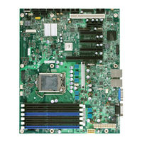
Intel S3420GP Specification (144 pages)
Product Specification
Brand:
Intel
| Category:
Server Board
| Size: 2 MB
Table of Contents
Revision History
2
Table of Contents
4
List of Figures
8
This Page Is Intentionally Left Blank
12
1 Introduction
13
Chapter Outline
13
Server Board Use Disclaimer
13
2 Overview
14
Intel Server Board S3420GP Feature Set
14
Table 1. Intel ® Server Board S3420GP Feature Set
14
Server Board Layout
17
Figure 1. Intel ® Server Board S3420GPLX Picture
17
Figure 2. Intel ® Server Board S3420GP Layout
18
Server Board Connector and Component Layout
18
Table 2. Major Board Components
19
Figure 3. Intel ® Server Board S3420GP - Key Connector and LED Indicator IDENTIFICATION
20
Intel Server Board S3420GP Mechanical Drawings
20
Figure 4. Intel ® Server Board S3420GP - Hole and Component Positions
21
Figure 5. Intel ® Server Board S3420GP - Major Connector Pin Location (1 of 2)
22
Figure 6. Intel ® Server Board S3420GP -Major Connector Pin Location (2 of 2)
23
Figure 7. Intel ® Server Board S3420GP - Primary Side Keepout Zone
24
Figure 8. Intel ® Server Board S3420GP - Secondary Side Keepout Zone
25
Figure 9. Intel ® Server Board S3420GP Rear I/O Layout
26
Server Board Rear I/O Layout
26
3 Functional Architecture
27
Figure 10. Intel ® Server Board S3420GP Functional Block Diagram for S3420GPLX
27
Figure 11. Intel ® Server Board S3420GP Functional Block Diagram from S3420GPLC
28
Processor Sub-System
29
Figure 12. Intel ® Server Board S3420GP Functional Block Diagram from S3420GPV
29
Intel ® Core TM Processor I3-500 Series and Intel ® Pentium ® Processor G6950
29
Intel ® Turbo Boost Technology
29
Intel ® Xeon ® Processor 3400 Series
29
Enhanced Intel Speedstep ® Technology
30
Simultaneous Multithreading (SMT)
30
Memory Subsystem
30
Memory Sizing and Configuration
30
Post Error Codes
31
Publishing System Memory
32
Memory Map and Population Rules
33
Table 3. Standard Platform DIMM Nomenclature
33
Table 4. Memory Configuration Table
34
Table 5. UDIMM Memory Configuration Rule
35
Table 6. UDIMM Maximum Configuration
35
Intel ® 3420 Chipset PCH
36
Table 7. RDIMM Memory Configuration Rule
36
Table 8. RDIMM Maximum Configuration
36
I/O Sub-System
37
PCI Express Interface
37
Serial ATA Support
38
USB 2.0 Support
38
Integrated Baseboard Management Controller
39
Figure 13. Integrated BMC Hardware
41
Integrated BMC Embedded LAN Channel
41
Optional RMM3 Advanced Management Board
41
Floppy Disk Controller
42
Keyboard and Mouse Support
42
Serial Ports
42
Table 10. Serial B Header (J1B1) Pin-Out
42
Table 9. Optional RMM3 Advanced Management Board Features
42
Wake-Up Control
43
Optional Intel SAS Entry RAID Module AXX4SASMOD
39
Video Support
43
Server Board S3420GPLC
43
Table 11. Video Modes
43
Table 12. Dual Video Modes
44
Video for Intel Server Board S3420GPV
44
Network Interface Controller (NIC)
45
Gige Controller 82574L
45
Gige PHY 82578DM
45
MAC Address Definition
45
Direct Cache Access (DCA)
46
I/Oat2)
46
Intel Virtualization Technology for Directed I/O
46
VT-D)
46
4 Platform Management
47
4.1 Feature Support
47
IPMI 2.0 Features
47
Figure 14. Server Management Bus (SMBUS) Block Diagram
47
Platform Management
47
Non-IPMI Features
48
Optional Advanced Management Feature Support
49
Enabling Advanced Management Features
49
Keyboard, Video, Mouse (KVM) Redirection
49
Media Redirection
50
Web Services for Management (WS-MAN)
50
Local Directory Authentication Protocol (LDAP)
51
Embedded Webserver
51
Management Engine (ME)
51
5 Server Management Capability for Intel® Server Board S3420GPV
52
Super I/O
52
Key Features of Super I/O
52
Sensor and Hardware Monitor
52
Figure 15. Setup Utility - Hardware Monitor Screen Display
53
Table 13. Setup Utility - Hardware Monitor Screen Fields
53
Fan Controller (Manual)
54
Figure 16. Setup Utility - Fan Controller (Manual) Display
55
Table 14. Setup Utility - Hardware Monitor Screen Fields
55
Voltage and Temperature Status Screen
56
Figure 17. Setup Utility - Voltage and Temperature Status Screen
56
Table 15. Setup Utility - Voltage and Temperature Status Fields
56
Smbios
57
Data Storage
57
Event Log and Viewer
57
Event Log Viewer in Setup
57
Figure 18. Event Log Viewer
58
6 BIOS User Interface
59
Logo/Diagnostic Screen
59
BIOS Boot Popup Menu
59
BIOS Setup Utility
59
Operation
60
Table 16. BIOS Setup Page Layout
60
Table 17. BIOS Setup: Keyboard Command Bar
61
Server Platform Setup Utility Screens
62
Figure 19. Setup Utility - Main Screen Display
63
Table 18. Setup Utility - Main Screen Fields
63
Advanced Screen
64
Figure 20. Setup Utility - Advanced Screen Display
65
Table 19. Setup Utility - Advanced Screen Display Fields
65
Figure 21. Setup Utility - Processor Configuration Screen Display
66
Table 20. Setup Utility - Processor Configuration Screen Fields
66
Figure 22. Setup Utility - Memory Configuration Screen Display
68
Table 21. Setup Utility - Memory Configuration Screen Fields
68
Figure 23. Setup Utility - Mass Storage Controller Configuration Screen Display
70
Table 22. Setup Utility - Mass Storage Controller Configuration Screen Fields
70
Figure 24. Setup Utility - Serial Port Configuration Screen Display
71
Table 23. Setup Utility - Serial Ports Configuration Screen Fields
71
Figure 25. Setup Utility - USB Controller Configuration Screen Display
72
Table 24. Setup Utility - USB Controller Configuration Screen Fields
73
Figure 26. Setup Utility - PCI Configuration Screen Display
74
Table 25. Setup Utility - PCI Configuration Screen Fields
74
Figure 27. Setup Utility - System Acoustic and Performance Configuration Screen Display
75
Table 26. Setup Utility - System Acoustic and Performance Configuration Screen Fields
75
Figure 28. Setup Utility - Security Configuration Screen Display
76
Table 27. Setup Utility - Security Configuration Screen Fields
76
Figure 29. Setup Utility - Server Management Configuraiton Screen Display
78
Table 28. Setup Utility - Server Management Configuration Screen Fields
78
Figure 30. Setup Utility - Console Redirection Screen Display
79
Table 29. Setup Utility - Console Redirection Configuration Fields
80
Figure 31. Setup Utility - Server Management System Information Screen Display
81
Table 30. Setup Utility - Server Management System Information Fields
81
Figure 32. Setup Utility - Boot Options Screen Display
82
Table 31. Setup Utility - Boot Options Screen Fields
82
Figure 33. Setup Utility - Delete Boot Option Screen Display
83
Figure 34. Setup Utility - Hard Disk Order Screen Display
84
Figure 35. Setup Utility - CDROM Order Screen Display
84
Table 32. Setup Utility - Delete Boot Option Fields
84
Table 33. Setup Utility - Hard Disk Order Fields
84
Figure 36. Setup Utility - Floppy Order Screen Display
85
Figure 37. Setup Utility - Network Device Order Screen Display
85
Table 34. Setup Utility - CDROM Order Fields
85
Table 35. Setup Utility - Floppy Order Fields
85
Loading BIOS Defaults
86
Figure 38. Setup Utility - Boot Manager Screen Display
86
Table 36. Setup Utility - Network Device Order Fields
86
Table 37. Setup Utility - Boot Manager Screen Fields
86
7 Connector/Header Locations and Pin-Outs
88
Board Connector Information
88
Power Connectors
88
Table 38. Board Connector Matrix
88
System Management Headers
89
Intel Remote Management Module
89
RMM3) Connector
89
Table 39. Baseboard Power Connector Pin-Out (J9A1)
89
Table 40. SSI Processor Power Connector Pin-Out (J9C1)
89
LCP/IPMB Header
90
HSBP Header
90
Table 41. Intel ® RMM3 Connector Pin-Out (J2C1)
90
Table 42. LPC/IPMB Header Pin-Out (J1H2)
90
Table 43. HSBP Header Pin-Out (J1J1)
90
SGPIO Header
91
Front Control Panel Connector
91
Table 44. SGPIO Header Pin-Out (J1J3)
91
Table 45. Front Panel SSI Standard 24-Pin Connector Pin-Out (J1C1)
91
NMI Button
92
Power Button
92
Reset Button
92
System Status Indicator LED
92
Table 46. System Status LED Indicator States
92
I/O Connectors
93
VGA Connector
93
Table 47. VGA Connector Pin-Out (J7A1)
93
Rear NIC and USB Connector
94
Table 48. RJ-45 10/100/1000 NIC Connector Pin-Out (J5A1)
94
Table 49. RJ-45 10/100/1000 NIC Connector Pin-Out (J6A1)
94
Sata
95
50-Pin PCI Express* Connector
95
Table 50. SATA Connector Pin-Out (J1H4, J1H1, J1G1, J1H3, J1G3, J1F4)
95
Table 51. 50-Pin PCI Express* Connector Pin-Out (J2H1)
95
Serial Port Connectors
96
USB Connector
96
Table 52. External Serial a Port Pin-Out (J8A1)
96
Table 53. Internal 9-Pin Serial B Header Pin-Out (J1B2)
96
Table 54. Internal USB Connector Pin-Out ( J1E1, J1D1)
96
PCI Express* Slot/Pci Slot/Riser Card Slot
97
Table 55. Pin-Out of Internal USB Connector for Floppy ( J1J2)
97
Table 56. Pin-Out of Internal USB Connector for Low-Profile Intel ® Z-U130 Value Solid State Drive (J3F2)
97
Table 57. Pin-Out of Adaptive Riser Slot/Pci Express Slot 6
97
Fan Headers
102
Table 58. SSI 4-Pin Fan Header Pin-Out (J6D1, J1J4, J6J2, J7J1, J6B1)
102
8 Jumper Blocks
103
Figure 39. Jumper Blocks (J1A2, J1F1, J1F3, J1F2 and J1F5)
103
Table 59. Server Board Jumpers (J1F1, J1F2, J1F3, J1F5, J1A2)
103
CMOS Clear and Password Reset Usage Procedure
104
Clearing the CMOS
104
Clearing the Password
104
Integrated BMC Force Update Procedure (Only for the Intel Server Board S3420GPLX and S3420GPLC)
105
ME Force Update Jumper
105
BIOS Recovery Jumper
106
9 Intel Light Guided Diagnostics
107
System Status LED (for the Intel ® Server Board S3420GPLX and S3420GPLC)
107
Table 60. Front Panel Status LED Behavior Summary
107
Post Code Diagnostic Leds
108
Table 61. POST Code Diagnostic LED Location
108
10 Design and Environmental Specifications
109
Intel Server Board S3420GP Design Specifications
109
10.2 Board-Level Calculated MTBF
109
Table 62. Server Board Design Specifications
109
10.3 Server Board Power Requirements
110
Processor Power Support
110
Figure 40. Power Distribution Block Diagram
110
Table 63. Intel ® Xeon ® Processor TDP Guidelines
110
10.4 Power Supply Output Requirements
111
Grounding
111
Standby Outputs
111
Remote Sense
111
Table 64. 350-W Load Ratings
111
Voltage Regulation
112
Dynamic Loading
112
Capacitive Loading
112
Closed-Loop Stability
112
Table 65. Voltage Regulation Limits
112
Table 66. Transient Load Requirements
112
Table 67. Capacitve Loading Conditions
112
Common Mode Noise
113
Ripple/Noise
113
Timing Requirements
113
Table 68. Ripple and Noise
113
Table 69. Output Voltage Timing
113
Figure 41. Output Voltage Timing
114
Table 70. Turn On/Off Timing
114
Residual Voltage Immunity in Standby Mode
115
Protection Circuits
115
Figure 42. Turn On/Off Timing (Power Supply Signals)
115
Table 71. Over-Current Protection (OCP)
116
Table 72. Over-Voltage Protection (OVP) Limits
116
11 Regulatory and Certification Information
117
11.1 Product Regulatory Compliance
117
11.1.1 Product Safety Compliance
117
11.1.2 Product EMC Compliance - Class a Compliance
117
11.1.3 Certifications/Registrations/Declarations
118
11.1.4 Product Ecology Requirements
118
11.2 Product Regulatory Compliance Markings
119
11.3 Electromagnetic Compatibility Notices
121
FCC Verification Statement (USA)
121
ICES-003 (Canada)
122
Europe (CE Declaration of Conformity)
122
VCCI (Japan)
122
BSMI (Taiwan)
123
RRL (Korea)
123
Appendix A: Integration and Usage Tips
124
Appendix B: Integrated BMC Sensor Tables
125
Table 73. Integrated BMC Core Sensors
127
Appendix C: POST Code Diagnostic LED Decoder
131
Figure 43. Diagnostic LED Placement Diagram
131
Table 74. POST Progress Code LED Example
131
Table 75. Diagnostic LED POST Code Decoder
132
Appendix D: POST Code Errors
135
Table 76. POST Error Messages and Handling
135
Table 77. POST Error Beep Codes
139
Appendix E: Supported Intel® Server Chassis
140
Glossary
141
Reference Documents
144
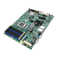
Intel S3420GP Manual (88 pages)
Intel - Server Motherboard
Brand:
Intel
| Category:
Server Board
| Size: 2 MB
Table of Contents
Safety Information
3
Wichtige Sicherheitshinweise
3
Consignes de Sécurité
3
Instrucciones de Seguridad Importantes
3
Important Safety Instructions
3
Warnings
5
Preface
7
About this Manual
7
Product Accessories
7
Additional Information and Software
8
Table of Contents
11
Chapter 1: Server Board Features
19
Figure 1. Intel ® Server Board S3420GP
19
Table 2. Server Board Features
20
Connector and Header Locations
23
Figure 2. Server Board Connector and Component Locations
24
Configuration Jumpers
25
Back Panel Connectors
26
Figure 3. Configuration Jumpers Location
26
Figure 4. Back Panel Connectors
26
Table 3. NIC LED Descriptions
26
Hardware Requirements
27
Processor
28
Memory
28
Table 4. Channel Slot Configuration
28
Power Supply
29
RAID Support
27
Optional Hardware
29
Intel SAS Entry RAID Module AXX4SASMOD
29
Figure 5. Intel ® SAS Entry RAID Module
30
Sas Raid Support
30
Intel Management Module
31
Intel Local Control Panel
31
Chapter 2: Server Utilities
33
Using the BIOS Setup Utility
33
Starting Setup
33
If You Cannot Access Setup
33
Setup Menus
33
Table 5. Setup Menu Key Use
34
Upgrading the BIOS
35
Preparing for the Upgrade
35
Upgrading the BIOS
36
Recovering the BIOS
36
Recovering the BIOS
37
Figure 6. BIOS Recovery Jumper
37
Clearing the Password
38
Figure 7. Password Recovery Jumper
38
Clearing the CMOS
38
Figure 8. CMOS Recovery Jumper
39
Figure 9. BMC Force Update Jumper
39
Updating Integrated BMC
39
Chapter 3: Hardware Installations and Upgrades
41
Before You Begin
41
Tools and Supplies Needed
41
Installing and Removing Memory
41
Installing Dimms
41
Removing Dimms
42
Figure 10. Installing Memory
42
Installing the Processor
43
Figure 11. Lifting the Load Lever
44
Figure 12. Open the Load Plate
44
Figure 13. Remove the Socket Protective Cover
45
Figure 14. Remove the Processor Protective Cover
45
Figure 15. Installing the Processor
46
Figure 16. Close the Load Plate and Socket Lever
46
Installing the Heatsink(S)
47
Figure 17. 2U Reference Heatsink Assembly
47
Removing a Processor
48
Installing a PCI Card
48
Figure 18. Removing the PCI Riser Assembly from the Server System
49
Figure 19. Installing a PCI Card in a Riser Card
49
Replacing the Backup Battery
50
Figure 20. Replacing the Backup Battery
51
Appendix A: LED Decoder
53
Figure 21. Diagnostic LED Placement Diagram
53
Table 6. POST Progress Code LED Example
54
Table 7. Diagnostic LED POST Code Decoder
54
Appendix B: Intel Server Issue Report Form
61
System Information
61
Appendix C: Getting Help
67
Warranty Information
67
Appendix D: Regulatory and Compliance Information
69
Product Regulatory Compliance
69
Product Safety Compliance
69
Certifications / Registrations / Declarations
70
Product Regulatory Compliance Markings
70
Table 8. Product Certification Markings
70
Electromagnetic Compatibility Notices
72
Fcc (Usa)
72
ICES-003 (Canada)
73
Europe (CE Declaration of Conformity)
73
VCCI (Japan)
73
BSMI (Taiwan)
74
RRL (Korea)
74
Restriction of Hazardous Substances (Rohs) Compliance
74
End-Of-Life / Product Recycling
75
Appendix E: Troubleshooting
77
System Boot Quiet Time
77
Resetting the System
77
Table 9. Resetting the System
77
Problems Following Initial System Installation
78
First Steps Checklist
78
Hardware Diagnostic Testing
79
Verifying Proper Operation of Key System Lights
79
Confirming Loading of the Operating System
79
Specific Problems and Corrective Actions
80
Power Light Does Not Light
80
No Characters Display on Screen
81
Characters Are Distorted or Incorrect
81
System Cooling Fans Do Not Rotate Properly
82
Drive Activity Light Does Not Light
82
CD-ROM Drive or DVD-ROM Drive Activity Light Does Not Light
82
Cannot Connect to a Server
83
Problems with Network
83
System Boots When Installing PCI Card
84
Problems with Newly Installed Application Software
84
Problems with Application Software that Ran Correctly Earlier
85
Devices Are Not Recognized under Device Manager (Microsoft Windows* Operating System)
85
Hard Drive(S) Are Not Recognized
85
Bootable CD-ROM Disk Is Not Detected
86
LED Information
86
Table 10. LED Information
86
BIOS POST Beep Codes
87
Table 11. POST Error Beep Codes
87
Advertisement
Intel S3420GP Installation Manual (39 pages)
For Server Board S3420GP
Brand:
Intel
| Category:
Software
| Size: 0 MB
Table of Contents
Table of Contents
3
Hardware Components
5
Software Components
5
Citrix* Xenserver* 5.5.0 Installation Recipe Overview
6
Additional Documentation
6
Enterprise-Ready Features in Xenserver* 5.5.0
6
System Requirements
9
Xenserver* Host System Requirements
9
Xencenter* Requirements
9
VM Support
10
Xenserver* Licensing
10
Install a License File with Xencenter
11
Install a License File with the "Xe" CLI
11
Install the Xenserver* and Xencenter* Software
12
Install the Xenserver* Host
12
Install or Upgrade the Xenserver* Host
13
Install Xencenter
17
Uninstall Xencenter
18
Xenserver* Installation and Deployment Scenarios
18
Xenserver* Hosts with Local Storage
18
Xenserver* Hosts with Shared NFS Storage
19
Setup an NFS Share on an NFS Server
19
Create a Pool-Level SR on the NFS Share
20
Xenserver* Hosts with Shared Iscsi Storage
20
Prepare the Iscsi Storage
21
Configure the Iscsi IQN for each Xenserver* Host Via the CLI
21
Create a Pool-Level SR on the Iscsi Share Via the CLI
22
Upgrade, Update, or Reinstall Xenserver
22
Prepare to Upgrade Xenserver* Hosts
22
Apply Xenserver* Updates
23
Apply Updates with the CLI
24
Reinstall the same Xenserver* Version
25
Backup and Restore Xenserver* Hosts and Vms
26
Backup Virtual Machine Metadata
26
Backup Pooled Installations
27
Restore the Backup on a New Set of Hosts
27
Xenserver* Hosts Backup Options
28
Backup a Xenserver* Host
28
Restore a Running Xenserver* Host
28
Restart a Crashed Xenserver* Host
29
Backup Vms
29
Appendix A: Troubleshooting
29
Appendix B: Maintenance Procedures
30
Setup the PXE Boot Environment
30
Setup a TFTP Server for PXE-Booting
30
Setup a DHCP Server
32
Setup the Installation Media Host
32
Prepare the Destination System
33
Create an Answerfile for Unattended PXE Installation
33
Installation Media Repository Format
35
Installation Media Repository Metadata
35
Package Metadata
36
Xs-Repository
37
Xs-Packages
37
Best Practice Notes
37
Appendix C: Xen Memory Usage
38
Set Control Domain Memory
38
Support Information
39
Intel® ESAA - Your Recipe for Success
39
Advertisement
Related Products
Intel SE72xx
Intel SE75xx
Intel SE8500
Intel S5520UR - Server Board Motherboard
INTEL SMALL BUSINESS SERVER
Intel Smart Connect
Intel RAID Controllers using the Intel RAID Software Stack 3
Intel Solid-State Drive Toolbox
Intel Small Business Advantage
Intel Smart Response
Intel Categories
Motherboard
Computer Hardware
Server
Desktop
Server Board
More Intel Manuals
Login
Sign In
OR
Sign in with Facebook
Sign in with Google
Upload manual
Upload from disk
Upload from URL