
Related Manuals for Intel SC5600LX - Server Chassis - Tower


Summary of Contents for Intel SC5600LX - Server Chassis - Tower
- Page 1 ® Intel Server Chassis SC5600 Service Guide ® A Guide for Technically Qualified Assemblers of Intel identified Subassemblies/Products Order Number: E39533-003 Revision 1.1...
- Page 2 Intel’s own chassis are designed and tested to meet the intended thermal requirements of these components when the fully integrated system is used together. It is the responsibility of the system integrator that chooses not to use Intel developed server building blocks to consult vendor datasheets and operating parameters to determine the amount of airflow required for their specific application and environmental conditions.
-
Page 3: Safety Information
Lisez attention toutes les consignes de sécurité et les mises en garde indiquées dans ce document avant de ® suivre toute instruction. Consultez Intel Server Boards and Server Chassis Safety Information sur le Intel Server Deployment Toolkit 3.0 CD ou bien rendez-vous sur le site: http://support.intel.com/support/motherboards/server/sb/cs-010770.htm... - Page 4 Take care to grip with, but not squeeze, the pliers or other tool you use to remove a jumper, or you may bend or break the pins on the board. Server Intel® Chassis SC5600 Service Guide...
-
Page 5: Preface
Server Board S5520HCT ® Intel Server Board S5500HCV ® Intel Workstation Board S5520SC ® ® The Intel Server Chassis SC5600BRP and SC5600LX are compatible with the following Intel Server Boards: ® Intel Server Board S5520HC ® Intel Server Board S5520HCT ® Intel... - Page 6 Server Chassis SC5600Base, Intel Server ® Chassis SC5600BRP), or four hot-swap fans with fan cables installed in the chassis (Intel Server Chassis SC5600LX) Front control panel board and front control panel cable installed in the chassis Front USB Panel and Front USB Panel cable installed in the chassis Air duct installed in the chassis ®...
-
Page 7: Additional Information And Software
Power Budget Analysis Tool within the allowed power budget See the section on the web page titled, “Installation and Use”. ® For software to manage your Intel Intel Server Management Software server See the section on the web page titled, “Installation and Use”. - Page 8 Preface <This page intentionally left blank.> Server viii Intel® Chassis SC5600 Service Guide...
-
Page 9: Table Of Contents
® Replacing a Fixed Fan (Intel Server Chassis SC5600Base and SC5400BRP only) ... 21 ® Removing and Installing Hot Swap Fans (Intel Server Chassis SC5600LX only) ....22 Removing Hot Swap Fans ..................... 22 Installing Hot Swap Fans ....................23 Removing and Installing a DVD- or CD-ROM Drive .............. - Page 10 Electrostatic Discharge (ESD) ..................69 Other Hazards ........................ 70 Deutsch ........................... 71 Sicherheitshinweise für den Server ................71 Sicherheitshinweise und Vorsichtsmaßnahmen ............71 Zielbenutzer der Anwendung ..................72 Standortauswahl ......................72 Handhabung von Geräten ..................... 72 Server Intel® Chassis SC5600 Service Guide...
- Page 11 Appendix E: Intel Server Issue Report Form ..........98 Appendix F: Warranty ..................103 ® Limited Warranty for Intel Chassis Subassembly Products ..........103 Extent of Limited Warranty ....................103 Warranty Limitations and Exclusions ................103 Limitations of Liability ....................104 How to Obtain Warranty Service .................
- Page 12 Figure 11. Installing the Front Bezel ..................... 18 Figure 12. Removing the Air Duct ....................19 ® Figure 13. Installing the Air Duct into Intel Server Chassis SC5600Base and SC5600BRP ..20 ® Figure 14. Installing the Air Duct into Intel Server Chassis SC5600LX ........
- Page 13 Figure 64. Installing Filler Panel board on the Chassis ............... 53 Figure 65. Inserting Hot Swap Power Supplies into Chassis ............54 Tables ® Table 1. Intel Server Chassis SC5600Base Features ..............1 ® Table 2. Intel Server Chassis SC5600BRP Features ..............2 ®...
-
Page 15: Server Chassis Features
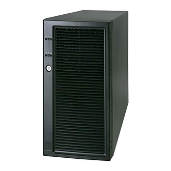
Server Chassis Features 1 Server Chassis Features ® This chapter briefly describes the main features of the Intel Server Chassis SC5600. This chapter provides a list of the server chassis features and diagrams showing the location of important components and connections on the server chassis. -
Page 16: Table 2. Intel Server Chassis Sc5600Brp Features
One 120-mm rear fan One air duct Processor heat sink is not included Processor Cooling Active processor heat sink(s) is required when used with compatible Intel server/workstation board. Supports up to 95-W processor Two front panel USB ports with Front Control Panel USB 2.0... - Page 17 One air duct Processor Heat Sink is not included Processor Cooling ® Active processor heat sink(s) is required when using with compatible Intel server/workstation board. Supports up to 95-W processor Two front panel USB ports with Front Control Panel USB 2.0...
- Page 18 Intel server/workstation board Supports up to 95-W processor Two front panel USB ports with Front Control Panel USB 2.0 Four back panel USB ports (depending on server/workstation board) One rear panel video port Video Intel® Server Chassis SC5600 Service Guide...
-
Page 19: Component Identification
4. Air Duct and Rear Fixed Fan 10. Fixed Drive Cage 4-Drive (accessory) 5. Front Fixed Fans (2) 11. Fixed Drive Cage 6-Drive 6. Hard Disk Drive Cage Release Mechanisms (2) ® Figure 2. Intel Server Chassis SC5600Base Components Location Server Intel® Chassis SC5600 Service Guide... -
Page 20: Figure 3. Intel
5. Air Duct 12. Hot-swap Drive Cage 4-Drive (accessory) 6. Hot-swap Fans – Large (2) 13. Hot-swap Drive Cage 6-Drive (accessory) 7. Hot-swap Fans –Small (2) ® Figure 3. Intel Server Chassis SC5600LX Components Location Intel® Server Chassis SC5600 Service Guide... -
Page 21: Front Control Panel
F. NIC2 Activity LED (green) B. Reset Button G. ID LED (blue) C. NIC1 Activity LED (green) H. Status LED (bi-color) D. Power Button I. NMI Button E. Hard Drive Activity LED (green) Figure 4. Front Control Panel Server Intel® Chassis SC5600 Service Guide... -
Page 22: Intel ® Local Control Panel
Local Control Panel provides enhanced system control by using a LCD display, which provides additional controls and indicators beyond the standard control panel. ® The following figure shows the features available on the Intel Local Control Panel. Intel® Server Chassis SC5600 Service Guide... -
Page 23: Back Panel Features
Callout Function LCD display (variable content) LCD up navigation button LCD down navigation button LCD backup level navigation button LCD command enter button ® Figure 5. Intel Local Control Panel Features Back Panel Features Server Intel® Chassis SC5600 Service Guide... -
Page 24: Figure 6. Server Chassis Back
PCI Card Latch Rear Serial B Connector (optional) AC Power Connector NOTE I/O ports vary, depending on the server/workstation board installed. See your server board documentation for port identification. Figure 6. Server Chassis Back Intel® Server Chassis SC5600 Service Guide... -
Page 25: Peripheral Devices
You must purchase the drives separately. The following figure shows the available options. Callout Function DVD-ROM drive/CD-ROM drive (Optional) Front USB ports (2) 4-Bay hot-swap hard disk drive bay (optional) 6-Bay hot-swap hard disk drive bay (optional) Figure 7. Optional Peripherals Server Intel® Chassis SC5600 Service Guide... -
Page 26: Standard And Optional Hot-Swap Drive Bays
Server chassis SC5600 into a rack. Intel provides a tool-less rail kit and a cable management arm to mount this server chassis into a rack. When installing the chassis into a rack, Intel recommends you install systems from the bottom of the rack to the top. In other words, install the first system in the rack into the bottom position of the rack;... -
Page 27: Tower Passive Processor Heat Sink (Fxxrgthsink)
Server Chassis Features Tower Passive Processor Heat Sink (FXXRGTHSINK) ® This tower passive heat sink (FXXRGTHSINK) is required when installing the Intel Server Board ® S5520HC/S5500HCV into the Intel Server Chassis SC5600LX. Two tower heat sinks are required for dual- processor installation. -
Page 28: Hardware Installations And Upgrades
Anti-static wrist strap and conductive foam pad (recommended) System Reference All references to the left, right, front, top, and bottom assume the reader is facing the front of the chassis as it would be positioned for normal operation. Intel® Server Chassis SC5600 Service Guide... -
Page 29: Removing And Installing The Chassis Cover
Removing the Chassis Cover ® You must operate the Intel Server Chassis SC5600 with the top cover in place to ensure proper cooling. You must remove the top cover to add or replace components inside of the platform. Before removing the top cover, power down the server and unplug all peripheral devices and the AC power cable. -
Page 30: Installing The Chassis Cover
The bezel assembly consists of two components: a front door and a sub-bezel. Observe the safety and ESD precautions at the beginning of this book. Power down the server and unplug all peripheral devices and the AC power cable. Intel® Server Chassis SC5600 Service Guide... -
Page 31: Installing The Front Bezel (Pedestal Configuration Only)
CAUTION This step applies to a pedestal configuration chassis only. For instructions on installing a bezel in a ® rack-mount configuration, refer to the Rack Conversion Kit Installation Guide: Intel Server Chassis SC5400 and SC5600. Open the outer bezel door of the bezel assembly (see letter “A” in the following figure). -
Page 32: Removing And Installing The Air Duct
Observe the safety and ESD precautions at the beginning of this book. See “Appendix B: Safety Information”. Power down the server and unplug all peripheral devices and the AC power cable. Remove the chassis cover. For instructions, see “Removing the Chassis Cover” on page 26. Intel® Server Chassis SC5600 Service Guide... -
Page 33: Installing The Air Duct
Figure 12. Removing the Air Duct Installing the Air Duct ® Installing the Air Duct in Intel Server Chassis SC5600Base and SC5600BRP If your system has two processors, remove the inner plastic inlet filler board from the inside of the air duct (see the following figure for inlet filler board removal details). -
Page 34: Figure 13. Installing The Air Duct Into Intel Server Chassis Sc5600Base And Sc5600Brp
Hardware Installations and Upgrades ® Figure 13. Installing the Air Duct into Intel Server Chassis SC5600Base and SC5600BRP NOTE Use care to avoid pinching the cables. ® Installing the Air Duct in the Intel Server Chassis SC5600LX Install the air duct. Make sure to align the air duct and chassis rear fan bracket alignment rails (see letter “E”... -
Page 35: Replacing A Fixed Fan (Intel Server Chassis Sc5600Base And Sc5400Brp Only)
Hardware Installations and Upgrades ® Figure 14. Installing the Air Duct into Intel Server Chassis SC5600LX NOTE Use care to avoid pinching the cables. Replacing a Fixed Fan ® (Intel Server Chassis SC5600Base and SC5400BRP only) NOTE ® ® This procedure applies only to the Intel... -
Page 36: Removing And Installing Hot Swap Fans (Intel Server Chassis Sc5600Lx Only)
Server ® Chassis SC5600Base and Intel Server Chassis SC5400BRP configurations ship with fixed fans. ® You cannot use the hot-swap fans from the Intel Server Chassis SC5400LX or SC5400LXi in the ® Intel Server Chassis SC5600LX. Observe the safety and ESD precautions at the beginning of this book. -
Page 37: Installing Hot Swap Fans
Server ® Chassis SC5600Base and Intel Server Chassis SC5400BRP configurations ship with fixed fans. ® You cannot use the hot-swap fans from the Intel Server Chassis SC5400LX or SC5400LXi in the ® Intel Server Chassis SC5600LX. Observe the safety and ESD precautions at the beginning of this book. -
Page 38: Removing And Installing A Dvd- Or Cd-Rom Drive
(see letter “A” in Figure 18). Remove the slides from the DVD or CD-ROM drive by pulling the slides away from the drive (see letter “B”). A gentle pull should release the slide from the side dimple on the drive. Intel® Server Chassis SC5600 Service Guide... -
Page 39: Installing A Dvd- Or Cd-Rom Drive
(see letter “A” in Figure 20). Remove the slides from the EMI shield by pulling the slides away from the EMI shield to release them from the EMI shield (see letter “B”). Server Intel® Chassis SC5600 Service Guide... -
Page 40: Figure 20. Removing Emi Shield/Slide Assembly From Upper Device Bay
Install the front bezel. For instructions, see “Removing and Installing the Front Bezel.” 10. Install the chassis cover. For instructions, see “Installing the Chassis Cover.” 11. Plug all peripheral devices and the AC power cable into the server. 12. Power up the server. Intel® Server Chassis SC5600 Service Guide... -
Page 41: Removing And Installing Fixed Hard Drive(S)
As an alternative, you may also fully remove the drive cage from its drive bay slot in the chassis. Take care, however, to position the drive cage horizontally before opening the drive cage doors or the drive rails will spill out. Figure 22. Removing Six-drive Fixed Drive Cage from Chassis Server Intel® Chassis SC5600 Service Guide... -
Page 42: Figure 23. Unlocking And Opening Upper Door Of Fixed Drive Cage
“B”). Figure 23. Unlocking and Opening Upper Door of Fixed Drive Cage Open the lower door. Figure 24. Opening Lower Door of Fixed Drive Cage 10. Remove the drive/slide assembly from the drive cage. Intel® Server Chassis SC5600 Service Guide... -
Page 43: Figure 25. Removing Drive/Slide Assembly From Fixed Drive Cage
11. Remove the device slides from the hard drive. If not replacing the hard drive, insert the empty device slides into the drive cage. Figure 26. Inserting Empty Device Slides into Fixed Drive Cage 12. Close the lower door of the drive cage. Server Intel® Chassis SC5600 Service Guide... -
Page 44: Figure 27. Closing Lower Door Of Fixed Drive Cage
Hardware Installations and Upgrades Figure 27. Closing Lower Door of Fixed Drive Cage 13. Close the upper door. Figure 28. Closing Upper Door of Fixed Drive Cage 14. Tighten the captive screw. Intel® Server Chassis SC5600 Service Guide... -
Page 45: Installing Fixed Hard Drive(S)
As an alternative, you may also fully remove the drive cage from its drive bay slot in the chassis. Take care, however, to position the drive cage horizontally before opening the drive cage doors or the drive rails will spill out. Server Intel® Chassis SC5600 Service Guide... -
Page 46: Figure 30. Removing Six-Drive Fixed Drive Cage From Chassis
Figure 30. Removing Six-drive Fixed Drive Cage from Chassis Loosen the captive screw (see letter “A” in Figure 31). Open the upper door (see letter “B”). Figure 31. Unlocking and Opening the Upper Door of Fixed Drive Cage Open the lower door. Intel® Server Chassis SC5600 Service Guide... -
Page 47: Figure 32. Opening Lower Door Of Fixed Drive Cage
Press firmly to secure device slides to the hard drive. Ensure the metal tabs on the device slides are facing the front of the hard drive and facing towards each other. Server Intel® Chassis SC5600 Service Guide... -
Page 48: Figure 34. Attaching Device Slides To Hard Drive
Figure 35. Inserting Drive/Slide Assembly into Drive Cage 11. For installation of additional hard drives into the drive cage, repeat the previous steps. 12. Close the lower door of the drive cage. Intel® Server Chassis SC5600 Service Guide... -
Page 49: Figure 36. Closing Lower Door Of Fixed Drive Cage
Hardware Installations and Upgrades Figure 36. Closing Lower Door of Fixed Drive Cage 13. Close the upper door. Figure 37. Closing Upper Door of Fixed Drive Cage 14. Tighten the captive screw. Server Intel® Chassis SC5600 Service Guide... -
Page 50: Figure 38. Tightening Thumb Screw
17. Install the front bezel. For instructions, see “Removing and Installing the Front Bezel.” 18. Install the chassis cover. For instructions, see “Installing the Chassis Cover” on page 27. 19. Plug all peripheral devices and the AC power cable into the server. 20. Power up the server. Intel® Server Chassis SC5600 Service Guide... -
Page 51: Routing Power Cables To Fixed Drives
Routing Power Cables to Fixed Drives Route the longest power cables to the 6-drive bay and shorter cables to the 4-drive bay and upper device bay. Figure 39. Routing Power Cables to Fixed Drives Server Intel® Chassis SC5600 Service Guide... -
Page 52: Routing Data Cables To Fixed Drives
Route SAS/SATA data cables through the chassis openings located near the bottom of the drive cage. Connect data cables to the respective fixed drive and to the appropriate connector on the server board. Figure 40. Routing SAS/SATA Data Cables Intel® Server Chassis SC5600 Service Guide... -
Page 53: Removing And Installing Hot Swap Drive(S)
Figure 41. Removing Drive Carrier from Hot Swap Cage Remove the four screws securing the hard drive to the drive carrier. Remove the hard drive from the drive carrier. Figure 42. Removing Hard Drive from Drive Carrier Server Intel® Chassis SC5600 Service Guide... -
Page 54: Figure 43. Securing Plastic Air Baffle In Drive Carrier
With the black lever open, insert the drive carrier into the drive cage. Once inserted, rotate the black lever upwards to latch the drive carrier into position. Figure 44. Inserting Drive Carrier into Hot Swap Cage Intel® Server Chassis SC5600 Service Guide... -
Page 55: Installing Hot Swap Drive(S)
Secure the hard drive to the drive carrier using the four screws previously attached to the plastic air baffle. Ensure the connector end of the hard drive is facing the back of the drive carrier. The label side of the hard drive should be facing up in the drive carrier. Server Intel® Chassis SC5600 Service Guide... -
Page 56: Figure 47. Securing Hard Drive To Drive Carrier
With the black lever open, insert the drive carrier into the drive cage. Once inserted, rotate the black lever upwards to latch the drive carrier into position. Figure 48. Inserting Drive Carrier into Hot Swap Cage Intel® Server Chassis SC5600 Service Guide... -
Page 57: Removing And Installing Pci Add-In Board(S)
PCI add-in card retainer from the chassis. Open the back panel PCI add-in card retention device (see letter “B”) by pressing open from the inside of the chassis. Figure 49. Preparing Chassis for Removal of PCI add-in board Server Intel® Chassis SC5600 Service Guide... -
Page 58: Installing Pci Add-In Board(S)
Open the back panel PCI add-in card retention device (see letter “B”) by pressing open from the inside of the chassis. Remove the PCI slot shield (see letter “C”), if it is not already removed, by pushing the shield out from the inside of the chassis. Intel® Server Chassis SC5600 Service Guide... -
Page 59: Figure 50. Preparing Chassis For Addition Of Pci Add-In Board
Hold the PCI add-in board by its top edge or upper corners. Firmly press the add-in board into an expansion slot on the server board (see letter “A” in the following figure). Close the back panel PCI add-in card retention device (see letter “B”). Server Intel® Chassis SC5600 Service Guide... -
Page 60: Figure 51. Installing Pci Add-In Board
Hardware Installations and Upgrades Figure 51. Installing PCI Add-in Board Repeat steps 2 through 10 until all PCI add-in cards are installed. Reinstall the PCI Add-in Card Retainer. Intel® Server Chassis SC5600 Service Guide... -
Page 61: Figure 52. Reinstalling Pci Add-In Card Retainer
11. Install the front bezel. For instructions, see “Removing and Installing the Front Bezel.” 12. Install the chassis cover. For instructions, see “Installing the Chassis Cover.” 13. Plug all peripheral devices and the AC power cable into the server. 14. Power up the server. Server Intel® Chassis SC5600 Service Guide... -
Page 62: Replacing A Hot Swap Power Supply
(see letter “B” in Figure 54) secures the hot swap power supply to the power supply cage. Figure 54. Installing Hot Swap Power Supply into Chassis Connect the power cable to the replaced power supply. Intel® Server Chassis SC5600 Service Guide... -
Page 63: Replacing A Fixed Power Supply
Secure the fixed power supply shield to the chassis with the eight screws. ® Connect the P1, P2, P3, and P4 cables to the server/workstation board. See the Intel server/workstation board Quick Start User’s Guide or User Guide for connection locations. -
Page 64: Replacing The Hot Swap Power Supply Power Distribution Board
Figure 56. Removing Hot Swap Power Supply from Chassis Disconnect all internal power cables from the chassis components and server/workstation board. See the Quick Start User’s Guide or Service Guide provided with your Intel server/workstation board for the appropriate connection location. -
Page 65: Figure 57. Removing Power Supply Filler Panel From Chassis
10. Remove the screws (see letter “A” and “B” in the following figure) securing the power distribution board to the hot swap supply cage, and detach the distribution board from the hot swap power supply cage. Server Intel® Chassis SC5600 Service Guide... -
Page 66: Figure 60. Removing Power Distribution Board From Hot Swap Power Supply Cage
Figure 61. Attaching Power Distribution Board to Hot Swap Power Supply Cage 12. Re-insert the hot swap power supply cage into the chassis power supply bay. Try to route the power cables to the appropriate area at the time of insertion (see Step 13). Intel® Server Chassis SC5600 Service Guide... -
Page 67: Figure 62. Inserting Hot Swap Power Supply Cage In Chassis
14. Reinstall the filler panel board, and install the screws to secure the filler panel board to the chassis (see letters “A” and “B” in Figure 64). Figure 64. Installing Filler Panel board on the Chassis 15. Insert the hot swap power supplies into the chassis (see Figure 65). Server Intel® Chassis SC5600 Service Guide... -
Page 68: Replacing The Control Panel
Replacing the Control Panel ® The steps for replacing the front control panel and the Intel Local Control Panel are nearly identical. Use the following steps for both varieties of the control panel. Where necessary, differences between the two control panels are noted. -
Page 69: Installing And/Or Removing A Server/Workstation Board
If installing a server board, refer to the Service Guide and/or Quick Start User’s Guide that shipped with ® your Intel server/workstation board for installation instructions. Use the mounting screws, bumpers, and standoffs (if necessary) that came with your chassis to secure the server/workstation board to the chassis. -
Page 70: Connecting And Disconnecting Cables To Or From Server Workstation Board
If your server has a hot swap power supply, remove the cables (that route toward the server/workstation board) to the chassis. ® See your Intel Server/Workstation Board Service Guide or Quick Start User’s Guide for cable connection locations. Intel® Server Chassis SC5600 Service Guide... -
Page 71: Technical Reference
The following table lists the total wattage available from the power subsystem for each voltage. If you configure your system heavily, ensure your loads do not exceed the combined total wattage of 725 Watts. For information about calculating the power usage for your configuration, see “Calculating Power Usage.” Server Intel® Chassis SC5600 Service Guide... -
Page 72: System Environmental Specification
Packaged: Operational after an 18-inch free fall. Acoustic Noise Base, BRP, and LX configurations - 5.8 BA LWA idle; 6.0 BA LWA typical operating Electrostatic Discharge Tested to 15 kilovolts (kV); no component damage (ESD) Intel® Server Chassis SC5600 Service Guide... -
Page 73: Current Usage
3rd Hard Drive 4th Hard Drive 5th Hard Drive 6th Hard Drive Expansion Board 1 Expansion Board 2 Expansion Board 3 Expansion Board 4 Expansion Board 5 Expansion Board 6 ® Intel Remote Management Module Server Intel® Chassis SC5600 Service Guide... -
Page 74: Table 9. Power Usage Worksheet 2
Do not exceed a combined power output of 170 W for the +5 V and +3.3 V outputs. Exceeding a combined 170 W will overload the power subsystem and may cause the power supplies to overheat and malfunction. Intel® Server Chassis SC5600 Service Guide... -
Page 75: Appendix A: Regulatory And Compliance Information
The final configuration of your end system product may require additional EMC compliance testing. For more information, please contact your local Intel representative. This is an FCC Class A device. Integration of it into a Class B chassis does not result in a Class B device. -
Page 76: Product Emc Compliance - Class A Compliance
This server chassis has been tested and verified to comply with the following electromagnetic compatibility (EMC) ® regulations when installed in a compatible Intel host system. For information on compatible host system(s), refer to Intel's Server Builder Web site or contact your local Intel representative. • FCC /ICES-003 - Emissions (USA/Canada) Verification •... -
Page 77: Product Regulatory Compliance Markings
Appendix A: Regulatory and Compliance Information Product Regulatory Compliance Markings ® This Intel server chassis product bears the following regulatory marks. Table 10. Product Regulatory Compliance Markings Regulatory Region Marking Compliance cULus Listing USA/Canada Marks GS Mark Germany CE Mark... -
Page 78: Electromagnetic Compatibility Notices
This digital apparatus does not exceed the Class A limits for radio noise emissions from digital apparatus set out in the interference-causing equipment standard entitled: "Digital Apparatus," ICES-003 of the Canadian Department of Communications. Intel® Server Chassis SC5600 Service Guide... -
Page 79: Europe (Ce Declaration Of Conformity)
Interchanging or use of other components will void the UL listing and other product certifications and approvals. Updated product information for configurations can be found on the Intel Server Builder Web site at the following URL: http://channel.intel.com/go/serverbuilder If you do not have access to Intel's Web address, please contact your local Intel representative. -
Page 80: Restriction Of Hazardous Substances (Rohs) Compliance
Restriction of Hazardous Substances (RoHS) Compliance Intel has a system in place to restrict the use of banned substances in accordance with the European Directive 2002/95/EC. Compliance is based on declaration that materials banned in the RoHS Directive are either (1) below all applicable substance threshold limits or (2) an approved/pending RoHS exemption applies. -
Page 81: Appendix B: Safety Information
To reduce the risk of bodily injury, electrical shock, fire, and equipment damage, read this document and ® observe all warnings and precautions in this guide before installing or maintaining your Intel server product. In the event of a conflict between the information in this document and information provided with the product or on the website for a particular product, the product documentation takes precedence. -
Page 82: Intended Application Uses
The power cord must have an electrical rating that is greater than that of the electrical current rating marked on the product. The power cord must have safety ground pin or contact that is suitable for the electrical outlet. Intel® Server Chassis SC5600 Service Guide... -
Page 83: System Access Warnings
Use a conductive foam pad if available but not the board wrapper. Do not slide board over any surface. Server Intel® Chassis SC5600 Service Guide... -
Page 84: Other Hazards
Caution: To avoid risk of radiation exposure and/or personal injury: • Do not open the enclosure of any laser peripheral or device. • Laser peripherals or devices are not user serviceable. • Return to manufacturer for servicing. Intel® Server Chassis SC5600 Service Guide... -
Page 85: Deutsch
Deutsch Sicherheitshinweise für den Server ® ® Das vorliegende Dokument bezieht sich auf Intel Serverplatinen, Intel Servergehäuse (Standfuß und Rack) sowie installierte Peripheriegeräte. Es enthält Warnungen und Vorsichtsmaßnahmen zur Vermeidung von Gefahren durch Verletzung, Stromschlag, Feuer und Beschädigungen von Geräten. Lesen Sie diese Dokument daher sorgfältig, ®... -
Page 86: Zielbenutzer Der Anwendung
Nehmen Sie keine Änderungen am Netzkabel vor, und verwenden Sie kein Kabel, das nicht genau dem geforderten Typ entspricht. Jedes Netzteil im System muß über ein eigenes Netzkabel angeschlossen werden. Einige Netzteile von Intel Servern verwenden Nullleitersicherungen. Vorsicht ist geboten im Umgang mit Netzteilen, welche Nullleitersicherungen verwenden, um das Risiko eines elektrischen Schlages zu vermeiden Das Netzteil in diesem Produkt enthält keine Teile, die vom Benutzer gewartet warden können. -
Page 87: Warnhinweise Für Den Systemzugang
Zur Vermeidung von Stromschlaggefahr müssen das Rack selbst und alle darin eingebauten Geräte ordnungsgemäß geerdet sein. Elektrostatische Entladungen (ESD) Vorsicht: Elektrostatische Entladungen können zur Beschädigung von Festplatten, Platinen und anderen Komponenten führen. Daher sollten Sie alle Arbeiten an einer ESD-Workstation ausführen. Steht ein solcher Server Intel® Chassis SC5600 Service Guide... -
Page 88: Andere Gefahren
® d’installer ou de mettre à jour votre produit serveur Intel En cas de conflit entre les informations fournies dans ce document et celles livrées avec le produit ou publiées sur le site Web pour un produit particulier, la documentation du produit prime. -
Page 89: Sécurité: Avertissements Et Mises En Garde
Signale des composants ou des surfaces soumis à des températures élevées. Indique de ne pas toucher aux pales de ventilateur, car cela peut entraîner des blessures. Indique de débrancher tous les cordons d’alimentation secteur pour déconnecter l’alimentation. Veuillez réutiliser la batterie Server Intel® Chassis SC5600 Service Guide... -
Page 90: Domaines D'utilisation Prévus
Vous devez les débrancher avant d’ouvrir le châssis, d’ajouter ou de supprimer un composant non connectable à chaud. Les alimentations de certains serveurs Intel sont munies de doubles fusibles pôle/neutre: veuillez observer les précautions d'usage afin d'éviter tout risque d'eléctrocution. -
Page 91: Avertissements Sur Le Cordon D'alimentation
Vous êtes responsable de l’installation d’un disjoncteur principal d’alimentation pour la totalité du rack. Ce disjoncteur principal doit être rapidement accessible et doit être étiqueté comme contrôlant toute l’unité, et pas uniquement le ou les serveurs. Server Intel® Chassis SC5600 Service Guide... -
Page 92: Décharges Électrostatiques (Esd)
Attention: Pour éviter tout risque d’exposition aux rayonnements et/ou de dommage personnel: • N’ouvrez pas l’enceinte d’un périphérique laser. • Les périphériques laser ne sont pas réparables par l’utilisateur. • Retournez-les au fabricant en cas de problème. Intel® Server Chassis SC5600 Service Guide... -
Page 93: Español
Información de seguridad del servidor ® ® Este documento se aplica a las tarjetas de servidor de Intel , las carcasas de servidor de Intel (montaje en bastidor y en pedestal) y los dispositivos periféricos. Para reducir el riesgo de daños corporales, descargas eléctricas, fuego y en el equipo, lea este documento y preste atención a todos las advertencias y precauciones de esta guía antes de... -
Page 94: Aplicaciones Y Usos Previstos
Algunas fuentes de alimentación de electricidad de los servidores de Intel utilizan el polo neutral del fuselaje. Para evitar riesgos de choques electricos use precauciónes al trabajar con las fuentes de alimentación que utilizan el polo neutral de fuselaje. -
Page 95: Advertencias Sobre El Cable De Alimentación
Instale el equipo en el bastidor comenzando desde la parte de abajo, con el equipo más pesado en la parte inferior del bastidor. Extraiga las piezas del equipo del bastidor de una a una. Server Intel® Chassis SC5600 Service Guide... -
Page 96: Descarga Electrostática (Esd)
Precaución: Para evitar el riesgo de la exposición a radiaciones o de daños personales: • No abra la caja de ningún periférico o dispositivo láser • Los periféricos o dispositivos láser no pueden ser reparados por el usuario • Haga que el fabricante los repare. Intel® Server Chassis SC5600 Service Guide... - Page 97 Appendix B: Safety Information 简体中文 服务器安全信息 ® ® 本文档适用于 Intel 服务器主板、Intel 服务器机箱(基座和机架固定件)和已安装的外设。为减少人身伤害、电击、火灾 ® 以及设备毁坏的危险,请在安装或维护 Intel 服务器产品之前阅读本文档并遵循本指南中的所有警告和预防措施。 如果本文档中的信息与特定产品的随附信息或 Web 站点信息之间存在不一致,请以产品文档为准。 服务器须由合格的技术人员进行集成和维护。 必须遵守本指南的规定和服务器手册的装配指导,以确保符合现有的产品认证和审 批。仅使用本指南中描述和规定的指定组件。使用其他产品/组件将使产品的 UL 认证和其他管理审批无效,并可能导致产品不符合销售地的产品法规。 安全警告与注意事项 为避免人身伤害与财产损失,安装本产品之前,请阅读以下所有安全指导和信息。 下面所列的安全符号可能在整个文档中使用并可能标注于产品和 / 或产品包装之上。 注意 注意 表示如果无视此项轻微人身伤害或财产损失的危险 警告 表示如果无视此严重人身伤害的危险 表示如果无视所示信息,即存在潜在的危险 表示如果不遵守安全指导,存在可导致严重伤害或死亡的电击危险 表示灼热组件或表面 表示请勿触摸风机叶片,否则可能致伤 表示拔下所有交流电线,断开交流电源 Server Intel®...
- Page 98 在易受闪电袭击的地区,我们建议将系统插入电涌抑制器并在闪电期间断开通信 线路与调制解调器之间的连接。 提供正确接地的墙壁插座。 提供足够的空间,以便拿取电源供应线,因为这是本产品的主要电源断开器。 设备操作规范 减少人身伤害或设备受损的危险: 移举设备时遵守当地的职业健康与安全要求。 借助机械手段或其他合适的手段移举设备。 拆除一切易分离组件,以降低重量并方便操作。 电源与电气警告 注意事项 电源按钮(如待机电源标记所示)并不能完全关闭系统的交流电源,只要系统已接 通电源,就存在 5V 待机电源。要从系统切断电源,须从墙壁电源插座中拔下交流电线。您的系统可能 不止使用一根交流电线。请确保所有的交流电线都已拔下。打开机箱或增加或去除 任何热插拔组件之前,确保交流电线已拔下。 若非所需的确切类型,请勿尝试修改或使用交流电线。系统的每个电源供应设备都 需要一根单独的交流电线。 本产品的电源供应设备包含非用户维修部件。请勿打开电源供应设备。电源供应设 备包含非常危险的电压级、电流级和能量级。请与生产商联系维修事宜。 替换热插拔电源供应设备时,请先拔下需替换的电源供应设备上的电源线,再将其 从服务器上移除。 为避免电击,请在打开服务器之前,关闭服务器并断开服务器上连接的电源线、电 信系统、网络和调制解调器。 电源线警告 如果产品未提供交流电线,请购买一根您所在国家批准使用的交流电线。 注意事项 为避免电击或火灾危险,请按如下所述对产品所用的电源线进行检查: Intel® Server Chassis SC5600 Service Guide...
- Page 99 电源线的电气额定值须大于产品上标注的电流额定值。 电源线须拥有适合插座的安全接地插头或触点。 电源线为交流电源的主要断开设备。插座须靠近设备并可随时断开。 电源线须插入所提供的拥有合适接地的插座。 系统使用警告 注意事项 为避免人身伤害或财产损失,无论何时检查产品内部,以下安全指导都适用: 关闭所有与本产品相连的外设。 按下电源按钮至关闭状态,关闭系统。 从系统或墙壁插座上拔下所有交流电线,断开交流电源。 断开与系统相连的所有线缆和通信线路。 卸除舱口盖时,保留所有螺钉及其他紧固件。完成产品内部检查之后,请 用螺钉或紧固件重新固定舱口盖。 请勿打开电源供应设备。电源供应设备内没有可维修部件。请与生产商联系 维修事宜. 增加或替换任何非热插拔组件之前,请关闭服务器电源并断开所有电源线 。 替换热插拔电源供应设备时,请先拔下需替换的电源供应设备上的电源线 ,然后再从服务器上移除电源供应设备。 注意事项 如果服务器一直在运行,任何已安装的处理器和吸热设备都可能很热。除非要增加 或移除热插拔组件,否则请待系统冷却后再开盖。为避免在热插拔组件安装过程中 接触灼热组件,移除或安装热插拔组件时务须小心。 Server Intel® Chassis SC5600 Service Guide...
- Page 100 静电放电 (ESD) 注意事项 ESD 会损坏磁盘驱动器、主板及其他部件。我们建议您执行 ESD 工作站的所有步骤。如果没有 ESD 工作站,则采取一些静电放电保护措施,操作部件时,戴上与服务器上的机箱接地 或任何未喷漆金属表面连接的防静电腕带。 操作主板时始终保持小心。它们可能对 ESD 非常敏感。拿持主板时只接触边缘。从保护包装中或从服务器上取出主板后,请将 主板组件侧面朝上放置在无静电的接地表面上。请使用导电泡沫垫(若有),不要 使用主板包装。请勿将主板在任何表面上滑动。 其他危险 替换电池 注意事项 不正确替换电池可能导致爆炸危险。替换电池时,请只使用设备生产商推荐使用的 电池。 请按当地法规处置电池。 请勿对电池充电。 请勿拆卸、刺穿或以其他方式损坏电池。 冷却和气流 注意事项 按照说明小心布置线缆,尽量减少气流阻塞和冷却问题。 为保证适当的冷却和气流,运行系统时请确保机箱盖已安装。未安装机箱盖即运行 系统可能导致系统部件受损。安装机箱盖的步骤如下: 首先检查并确保系统内没有遗留的未固定工具或部件。 检查线缆、内插板和其他组件已正确安装。 按产品说明安装机箱盖。 激光外设或激光设备 Intel® Server Chassis SC5600 Service Guide...
- Page 101 Appendix B: Safety Information 注意事项 为避免幅射暴露和/或人身伤害: 请勿打开任何激光外设或激光设备的外壳 激光外设或激光设备为非用户维修设备 请与生产商联系维修事宜 Server Intel® Chassis SC5600 Service Guide...
-
Page 102: Appendix C: Installation/Assembly Safety Instructions
Attach the covers to the chassis with the screws removed earlier, and tighten them firmly. Insert and lock the padlock to the system to prevent unauthorized access inside the system. Connect all external cables and the AC power cord(s) to the system. Intel® Server Chassis SC5600 Service Guide... -
Page 103: Deutsch
I/O Anschlüssen oder Ports ab. Tragen Sie ein geerdetes Antistatik Gelenkband, um elektrostatische Ladungen (ESD) über blanke Metallstellen bei der Handhabung der Komponenten zu vermeiden. Schalten Sie das System niemals ohne ordnungsgemäß montiertes Gehäuse ein. Server Intel® Chassis SC5600 Service Guide... - Page 104 Sturms sollte keine Verbindung der Telekommunikationsleitungen mit dem Modem bestehen; • "mit einer geerdeten Wechselstromsteckdose ausgerüstet sein; • "über ausreichend Platz verfügen, um Zugang zu den Netzkabeln zu gewährleisten, da der Stromanschluß des Produkts hauptsächlich über die Kabel unterbrochen wird Intel® Server Chassis SC5600 Service Guide...
-
Page 105: Français
Le microprocesseur et le dissipateur de chaleur peuvent être chauds si le système a été sous tension. Faites également attention aux broches aiguës des cartes et aux bords tranchants du capot. Nous vous recommandons l'usage de gants de protection. Server Intel® Chassis SC5600 Service Guide... - Page 106 • "Muni d'une prise murale correctement mise à la terre. • "Suffisamment spacieux pour vous permettre d'accéder aux câbles d'alimentation (ceux-ci étant le seul moyen de mettre le système hors tension). Intel® Server Chassis SC5600 Service Guide...
-
Page 107: Español
Si el sistema ha estado en funcionamiento, el microprocesador y el disipador de calor pueden estar aún calientes. También conviene tener en cuenta que en el chasis o en el tablero puede haber piezas cortantes o punzantes. Por ello, se recomienda precaución y el uso de guantes protectores. Server Intel® Chassis SC5600 Service Guide... - Page 108 • "Provisto de una toma de tierra correctamente instalada. • "Provisto de espacio suficiente como para acceder a los cables de alimentación, ya que éstos hacen de medio principal de desconexión del sistema. Intel® Server Chassis SC5600 Service Guide...
-
Page 109: Italiano
Se il sistema è stato a lungo in funzione, il microprocessore e il dissipatore di calore potrebbero essere surriscaldati. Fare attenzione alla presenza di piedini appuntiti e parti taglienti sulle schede e sul telaio. È consigliabile l'uso di guanti di protezione. Server Intel® Chassis SC5600 Service Guide... - Page 110 In caso di temporali, scollegare le linee di comunicazione dal modem. • "Dotata di una presa a muro correttamente installata. • "Dotata di spazio sufficiente ad accedere ai cavi di alimentazione, i quali rappresentano il mezzo principale di scollegamento del sistema. Intel® Server Chassis SC5600 Service Guide...
-
Page 111: Appendix D: Getting Help
A searchable knowledgebase to search for product information throughout the • support site Send an email to Intel’s technical support center using the following online form if you still cannot obtain a solution to your issue. Lastly, you can contact an Intel support representative using one of the following support phone numbers. -
Page 112: Appendix E: Intel Server Issue Report Form
NOTE: Filling out this form completely is required for any escalation. Note: An online/automatic submission version of this form is available at http://support.intel.com/support/motherboards/server/chassis/sc5600/. For the fastest service, please submit your form via the Internet. Customer Contact Information: Customer Support Case# : ®... - Page 113 (1U, Passive w/air ducting, Active w/fan, and so on) Memory: Manufacturer Part Number DRAM Part Number On Intel tested list? Add-in adapters (Example: NICs, Management Adapters, Serial Expansion Cards, PCI- Express* Adapters, RAID Controllers, SCSI Controllers, and so on): Type Slot...
- Page 114 Has the latest RAID firmware been tried? (Yes/No): RAID driver version: Has the latest RAID driver been tried? (Yes/No): RAID volumes configuration (disks & RAID level): RAID volume use (Boot device/Data Volume): Is BBU (Battery Backup Unit) installed? (Yes/No): Intel® Server Chassis SC5600 Service Guide...
- Page 115 ® Appendix E: Intel Server Issue Report Form BBU part number Detailed description of issue: Troubleshooting tried: Steps to replicate the issue: Server Intel® Chassis SC5600 Service Guide...
- Page 116 Server Issue Report Form Issue impact statements: Do you have any potential Intel system, or component purchases that this issue is holding up? If yes, please provide a brief description below. Do you have systems already purchased that are not being delivered to your customers because of this issue? If yes, please provide a brief description below.
-
Page 117: Appendix F: Warranty
Product or to refund the then-current value of the Product. In no event will Intel be liable for any other costs associated with the replacement or repair of Product, including labor, installation or other costs incurred by buyer and in particular, any costs relating to the removal or replacement of any product soldered or otherwise permanently affixed to any printed circuit board. -
Page 118: Limitations Of Liability
Intel's responsibility under this, or any other warranty, implied or expressed, is limited to repair, replacement, or refund, as set forth above. These remedies are the sole and exclusive remedies for any breach of warranty. Intel is not responsible for direct, special, incidental, or consequential damages resulting from any breach of warranty under...
Need help?
Do you have a question about the SC5600LX - Server Chassis - Tower and is the answer not in the manual?
Questions and answers