
Related Manuals for Intel SC5400LX


Summary of Contents for Intel SC5400LX
- Page 1 Intel® Server Chassis SC5400 User’s Guide A Guide for Technically Qualified Assemblers of Intel® Identified Subassemblies/ Products Intel Order Number D38435-005...
- Page 2 Intel products are not designed, intended or authorized for use in any medical, life saving, or life sustaining applications or for any other application in which the failure of the Intel product could create a situation where personal injury or death may occur.
-
Page 3: Safety Information
Safety Information Important Safety Instructions Read all caution and safety statements in this document before performing any of the instructions. See also Intel Server Boards and Server Chassis Safety Information on the ® Intel Server Deployment Toolkit CD and/or at http://support.intel.com/support/... - Page 4 Use a conductive foam pad if available but not the board wrapper. Do not slide board over any surface. Intel® Server Chassis SC5400 User’s Guide...
- Page 5 Take care to grip with, but not squeeze, the pliers or other tool you use to remove a jumper, or you may bend or break the pins on the board. Intel® Server Chassis SC5400 User’s Guide...
- Page 6 Intel® Server Chassis SC5400 User’s Guide...
-
Page 7: Preface
Manual Organization ® Chapter 1 provides a brief overview of the Intel Server Chassis SC5400. In this chapter, you will find a list of the server chassis features, photos of the product, and product diagrams to help you identify components and their locations. -
Page 8: Product Contents, Order Options, And Accessories
Processor, memory DIMMs, hard drive, floppy drive, CD-ROM or DVD-ROM drive, RAID controller, operating system. For information about which accessories, memory, processors, and third-party hardware have been tested and can be used with your board, and for ordering information for Intel products, see http://support.intel.com/support/motherboards/server/chassis/SC5400/ compat.htm. -
Page 9: Additional Information And Software
Tested Hardware Operating Systems List boards, adapter cards) and operating systems that have been tested with this product ® For software to manage Intel System Management Software ® your Intel server For diagnostics test Diagnostics software Intel® Server Chassis SC5400 User’s Guide... - Page 10 Intel® Server Chassis SC5400 User’s Guide...
-
Page 11: Table Of Contents
Removing the Processor and Memory Air Ducts ............20 Installing the Processor and Memory Air Ducts ............21 ® Replacing a Fixed Fan (Intel Server Chassis SC5400Base SC5400BRP only) ..23 ® Removing and Installing Hot Swap Fans (Intel Server Chassis SC5400LX or Intel® Server Chassis SC5400 User’s Guide... - Page 12 System Environmental Specifications ................. 64 Current Usage ......................65 Calculating Power Usage ..................65 Appendix A: Getting Help ..................67 World Wide Web ......................67 Telephone ........................67 Appendix B: Regulatory and Compliance Information .........71 Intel® Server Chassis SC5400 User’s Guide...
- Page 13 Sicherheitshinweise für den Server ................93 Sicherheitshinweise und Vorsichtsmaßnahmen .............93 Zielbenutzer der Anwendung ..................94 Standortauswahl .....................94 Handhabung von Geräten ..................94 Warnungen zu Netzspannung und Elektrizität ............95 Warnhinweise für den Systemzugang ..............96 Warnhinweise für Racks ..................97 Intel® Server Chassis SC5400 User’s Guide xiii...
- Page 14 Advertencias sobre el montaje en bastidor ............108 Descarga electrostática (ESD) ................109 Appendix E: Installation/Assembly Safety Instructions ........117 English ........................117 Deutsch ........................119 Français ........................122 Español ........................124 Italiano ........................126 Intel® Server Chassis SC5400 User’s Guide...
- Page 15 Figure 39. Routing Power Cables to Fixed Drives ..............40 Figure 40. Routing SAS/SATA Data Cables ................41 Figure 41. Releasing Drive Carrier from Hot Swap Cage ............42 Figure 42. Removing Hard Drive from Drive Carrier ............... 42 Intel® Server Chassis SC5400 User’s Guide...
- Page 16 Figure 60. Removing Power Distribution Board..............56 Figure 61. Securing Power Distribution Board to Power Supply Cage ........57 Figure 62. Re-installing Center Divider ................... 58 Figure 63. Installing Hot Swap Power Supply into Chassis ............ 58 Intel® Server Chassis SC5400 User’s Guide...
- Page 17 Table 8. Environmental Specifications ..................64 Table 9. Power Usage Worksheet ...................65 Table 10. Power Usage Worksheet 2 ..................66 Table 11. Product Regulatory Compliance Markings ..............72 Table 12. Product Ecology Compliance Markings ..............78 Table 13. Other Markings ......................80 Intel® Server Chassis SC5400 User’s Guide xvii...
- Page 18 Intel® Server Chassis SC5400 User’s Guide...
-
Page 19: Chapter 1: Server Chassis Features
Server Chassis Features ® This chapter briefly describes the main features of the Intel Server Chassis SC5400. This chapter provides a list of the server chassis features, as well as diagrams showing the location of important components and connections on the server chassis. -
Page 20: Table 1. Server Chassis Features (Base Sku)
® Table 1 summarizes the features of the Intel Server Chassis SC5400 Base SKU Table 1. Server Chassis Features (BASE SKU) Feature Description • Dimensions 16.6 inches high (Pedestal: 17 inches) • 8.6 inches wide • 27.4 inches deep (Pedestal: 28.4 inches) •... -
Page 21: Table 2. Server Chassis Features (Brp Sku)
Two front panel USB ports with Front Control Panel • Four back panel USB ports • Video One front panel video port (available only with Front Control Panel) • One rear panel video port Intel® Server Chassis SC5400 User’s Guide... -
Page 22: Table 3. Server Chassis Features (Lx Sku)
Two front panel USB ports with Front Control Panel • Four back panel USB ports • Video One front panel video port (available only with Standard Control Panel) • One rear panel video port Intel® Server Chassis SC5400 User’s Guide... -
Page 23: Table 4. Server Chassis Features (Lxi Sku)
Two front panel USB ports with Front Control Panel • Four back panel USB ports • Video One front panel video port (available only with Standard Control Panel) • One rear panel video port Intel® Server Chassis SC5400 User’s Guide... -
Page 24: Component Identification
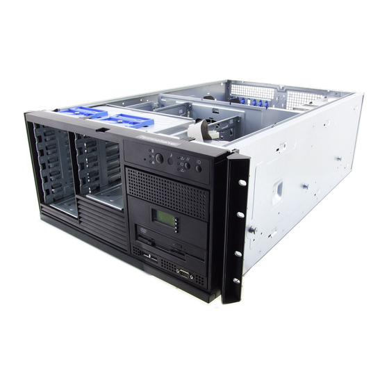
PCI Add-in Card Panel 5.25-inch Device Bays Memory Air Duct Front Panel USB/Serial B Processor Air Duct Fixed Drive Cage 4-Drive (accessory) Fixed Fans (2) Fixed Drive Cage 6-Drive Figure 2. Internal Component Locations Intel® Server Chassis SC5400 User’s Guide... -
Page 25: Front Control Panel
Front Control Panel ® The following figure shows the features available on the Front Control Panel. The Intel Local Control Panel is optional. TP00701 ID Toggle Switch NIC2 Activity LED (green) Reset Button ID LED (blue) NIC 1 Activity LED (green) -
Page 26: Table 5. Front Control Panel Led Descriptions
Blink LAN activity Idle NIC2 activity Green Linked Blink LAN activity Idle ID LED (rack Blue Blink Server identification; toggled by ID button or only) software Server identification; toggled by ID button or software Intel® Server Chassis SC5400 User’s Guide... -
Page 27: Intel ® Local Control Panel
Local Control Panel. The Intel® Local Control Panel is optional. ® Note: The Intel® Local Control Panel requires the installation of the Intel Remote Management Module. See your server board documentation to determine if this control panel is compatible with your server board. -
Page 28: Back Panel Features
PCI Card Latch Rear Serial B Connector (optional) Knockout AC Power Connector Note: I/O connectors vary, depending on the server board installed. See your server board documentation for port identification. Figure 5. Server Chassis Back Intel® Server Chassis SC5400 User’s Guide... -
Page 29: Peripheral Devices
CD-ROM drive, or a DVD-ROM drive. The drives must be purchased separately. The following figure shows the available options. AF000552 Slimline floppy drive / DVD-ROM drive / CD-ROM drive USB ports (2) Hard drive bays Figure 6. Optional Peripherals Intel® Server Chassis SC5400 User’s Guide... -
Page 30: Standard And Optional Hot-Swap Drive Bays
Server Chassis SC5400 does not support all slimline floppy, CD-ROM or DVD-ROM hard drives. See “Additional Information and Software” on page ix for an Internet link to a list of supported hardware. Intel provides accessory kits for these drives. Intel® Server Chassis SC5400 User’s Guide... -
Page 31: Intel ® Remote Management Module
When installing the chassis into a rack, Intel recommends you install systems from the bottom of the rack to the top. In other words, install the first system in the rack into the bottom position of the rack, the second system in the second position from the bottom, and so on. - Page 32 Intel® Server Chassis SC5400 User’s Guide...
-
Page 33: Chapter 2: Hardware Installations And Upgrades
Anti-static wrist strap and conductive foam pad (recommended) System References All references to left, right, front, top, and bottom assume the reader is facing the front of the chassis as it would be positioned for normal operation. Intel® Server Chassis SC5400 User’s Guide... -
Page 34: Removing And Installing The Chassis Cover
While holding in the blue button at the top of the chassis (see letter "B"), slide the top cover back until it stops. Lift the cover outward to remove it. AF000555 Figure 7. Removing the Chassis Cover Intel® Server Chassis SC5400 User’s Guide... -
Page 35: Installing The Chassis Cover
2. Latch the cover securely to the chassis. 3. If the chassis will be re-shipped, secure the chassis cover to the chassis with the access cover screw (see letter “A” in the following figure). AF000572 Figure 8. Installing the Chassis Cover Intel® Server Chassis SC5400 User’s Guide... -
Page 36: Removing And Installing The Front Bezel
7. If the bezel assembly does not immediately disconnect from the chassis, tap the left-hand side of the bezel assembly to disengage the bezel hooks on the right-hand side of the chassis. AF000557 Figure 9. Removing the Front Bezel Intel® Server Chassis SC5400 User’s Guide... -
Page 37: Installing The Front Bezel (Pedestal Only)
6. Rotate the bezel assembly toward the chassis. 7. Latch the two plastic tabs (see letter “E”) on the left side of the bezel assembly to the chassis. 40 ° Max AF000558 Figure 10. Installing the Front Bezel Intel® Server Chassis SC5400 User’s Guide... -
Page 38: Removing And Installing The Processor And Memory Air Ducts
“A” in the following figure). 5. Detach the memory air duct from the processor air duct (see letter “B”). 6. Remove the processor air duct (see letter “C”). AF000321 Figure 11. Removing the Processor and Memory Air Ducts Intel® Server Chassis SC5400 User’s Guide... -
Page 39: Installing The Processor And Memory Air Ducts
3. Install the memory air duct next by holding the large tab-end of the memory air duct at a downward angle and then inserting the large tab (see letter “C”) from the underside into the matching slot on the processor air duct. Intel® Server Chassis SC5400 User’s Guide... -
Page 40: Figure 13. Installing The Processor And Memory Air Ducts
Figure 13. Installing the Processor and Memory Air Ducts Caution: The processor air duct interlocks with the memory air duct in two places before latching into place. Note: Use care to avoid pinching the cables. Intel® Server Chassis SC5400 User’s Guide... -
Page 41: Replacing A Fixed Fan (Intel ® Server Chassis Sc5400Base Sc5400Brp Only)
Figure 14. Removing a Fixed Fan 6. Install new 92-mm or 120-mm fixed fan. ® 7. Connect fan power cable to the server board. See the Intel server board Quick Start User’s Guide or User Guide for appropriate connection location. -
Page 42: Removing And Installing Hot Swap Fans
® ® The hot-swap fans from the Intel Server Chassis SC5300LX cannot be used in the Intel Server Chassis SC5400LX or SC5400LXi. 1. Observe the safety and ESD precautions at the beginning of this book. 2. Remove the chassis cover. For instructions, see “Removing the Chassis Cover”... -
Page 43: Installing Hot Swap Fans
® ® The hot-swap fans from the Intel Server Chassis SC5300 LX cannot be used in the Intel Server Chassis SC5400LX or SC5400LXi. 1. Observe the safety and ESD precautions at the beginning of this book. 2. Remove the chassis cover if not removed in a previous step. For instructions, see “Removing the Chassis Cover”... -
Page 44: Installing And Removing A Slimline Usb Floppy/Cd/Dvd Combo Kit
(see letter “B”). A gentle pull should release the slide from the side dimple on the drive tray. AF000575 Figure 17. Removing Slide/Drive Assembly from Upper Device Bay Intel® Server Chassis SC5400 User’s Guide... -
Page 45: Removing And Installing A Dvd Or Cd-Rom Drive
“Removing the Chassis Cover” on page 4. Remove the front bezel if it is installed. For instructions, see “Removing and Installing the Front Bezel” on page 5. Disconnect the power and data cables to the DVD/CD-ROM drive. Intel® Server Chassis SC5400 User’s Guide... -
Page 46: Figure 19. Re-Inserting Empty Emi Shield/Slide Assembly Into Chassis
Bezel” on page 9. Install the chassis cover. For instructions, see “Installing the Chassis Cover” on page 10. Plug all peripheral devices and the AC power cable into the server. 11. Power up the server. Intel® Server Chassis SC5400 User’s Guide... -
Page 47: Installing A Dvd Or Cd-Rom Drive
6. Attach slides to the DVD or CD-ROM drive by pressing the slides firmly into the side dimples on the DVD or CD-ROM drive. AF000576 Figure 21. Attaching Slides to a DVD or CD-ROM Drive Intel® Server Chassis SC5400 User’s Guide... -
Page 48: Removing And Installing Fixed Hard Drive(S)
Note: As an alternative, you may also fully remove the drive cage from its drive bay slot in the chassis. Take care, however, to position the drive cage horizontally before opening the drive cage doors or the drive rails will spill out. Intel® Server Chassis SC5400 User’s Guide... -
Page 49: Figure 22. Removing Six-Drive Fixed Drive Cage From Chassis
8. Loosen the thumb screw (see letter “A” in the following figure). Open the upper door of the drive cage (see letter “B”). AF000579 Figure 23. Unlocking and Opening Upper Door of Fixed Drive Cage Intel® Server Chassis SC5400 User’s Guide... -
Page 50: Figure 24. Opening Lower Door Of Fixed Drive Cage
9. Open the lower door. AF000946 Figure 24. Opening Lower Door of Fixed Drive Cage 10. Remove the drive/slide assembly from the drive cage. AF000588 Figure 25. Removing Drive/Slide Assembly from Drive Cage Intel® Server Chassis SC5400 User’s Guide... -
Page 51: Figure 26. Inserting Empty Device Slides Into Drive Cage
11. Remove the device slides from hard drive. If not replacing hard drive, insert empty device slides into drive cage. AF000947 Figure 26. Inserting Empty Device Slides into Drive Cage 12. Close the lower door of drive cage. AF000948 Figure 27. Closing Lower Door of Fixed Drive Cage Intel® Server Chassis SC5400 User’s Guide... -
Page 52: Figure 28. Closing Upper Door Of Fixed Drive Cage
Bezel” on page 18. Install the chassis cover. For instructions, see “Installing the Chassis Cover” on page 19. Plug all peripheral devices and the AC power cable into the server. 20. Power up the server. Intel® Server Chassis SC5400 User’s Guide... -
Page 53: Installing Fixed Hard Drive(S)
Take care, however, to position the drive cage horizontally before opening the drive cage doors or the drive rails will spill out. TP00906 Figure 30. Removing Six-drive Fixed Drive Cage from Chassis Intel® Server Chassis SC5400 User’s Guide... -
Page 54: Figure 31. Unlocking And Opening Upper Door Of Fixed Drive Cage
6. Loosen the captive screw (see letter “A” in the following figure). Open the upper door (see letter “B”). AF000579 Figure 31. Unlocking and Opening Upper Door of Fixed Drive Cage 7. Open the lower door. AF000580 Figure 32. Opening Lower Door of Fixed Drive Cage Intel® Server Chassis SC5400 User’s Guide... -
Page 55: Figure 33. Removing Slides From Drive Cage
Ensure that the metal tabs on the device slides are facing the front of the hard drive and facing towards each other. AF000582 Figure 34. Attaching Device Slides to Hard Drive Intel® Server Chassis SC5400 User’s Guide... -
Page 56: Figure 35. Inserting Drive/Slide Assembly Into Drive Cage
Figure 35. Inserting Drive/Slide Assembly into Drive Cage 11. Repeat above steps for installation of additional hard drives into the drive cage. 12. Close the lower door of drive cage. AF000584 Figure 36. Closing Lower Door of Fixed Drive Cage Intel® Server Chassis SC5400 User’s Guide... -
Page 57: Figure 37. Closing Upper Door Of Fixed Drive Cage
Bezel” on page 18. Install the chassis cover. For instructions, see “Installing the Chassis Cover” on page 19. Plug all peripheral devices and the AC power cable into the server. 20. Power up the server. Intel® Server Chassis SC5400 User’s Guide... -
Page 58: Routing Power Cables To Fixed Drives
P3, P4 and P5 power cables route to removable drives. • P6, P7, P8, P9, P10 and P11 power cables (standard SAS/SATA); route as appropriate. • P12 and P13 power cables (SATA); route as appropriate. Intel® Server Chassis SC5400 User’s Guide... -
Page 59: Routing Data Cables To Fixed Drives
SAS/SATA Cable Routing Chassis Primary Side View SAS/SATA To 4-Drive Cage IDE/USB/Front Panel Cables 4/6 Drive Bay Cables Chassis Primary Side View To 6-Drive Cage AF000509 Figure 40. Routing SAS/SATA Data Cables Intel® Server Chassis SC5400 User’s Guide... -
Page 60: Removing And Installing Hot Swap Drive(S)
Figure 41. Releasing Drive Carrier from Hot Swap Cage 2. Remove the four screws securing the hard drive to the drive carrier. Remove the hard drive from the drive carrier. AF000595 Figure 42. Removing Hard Drive from Drive Carrier Intel® Server Chassis SC5400 User’s Guide... -
Page 61: Figure 43. Installing Plastic Air Baffle In Drive Carrier
4. With the black lever open, insert the drive carrier into the drive cage. Once inserted, rotate the black lever upwards to latch the drive carrier into position. AF000592 Figure 44. Inserting Drive Carrier into Hot Swap Cage Intel® Server Chassis SC5400 User’s Guide... -
Page 62: Installing Hot Swap Drive(S)
Ensure that the connector end of the hard drive is facing the back of the drive carrier. The label side of the hard drive should be facing up in the drive carrier. Intel® Server Chassis SC5400 User’s Guide... -
Page 63: Removing And Installing Pci Add-In Board(S)
5. Remove any cables attached to the add-in card, if necessary. 6. Remove the PCI add-in card retainer. Press in on the two plastic tabs (see letter “A” in the following figure) to release the PCI add-in card retainer from the chassis. Intel® Server Chassis SC5400 User’s Guide... -
Page 64: Figure 49. Preparing Chassis For Removal Of Pci Add-In Board
Open the back panel PCI add-in card retention device (see letter “B”) by pressing open from the inside of the chassis. AF000600 Figure 49. Preparing Chassis for Removal of PCI Add-in Board Intel® Server Chassis SC5400 User’s Guide... -
Page 65: Installing Pci Add-In Board(S)
3. Remove the chassis cover. For instructions, see “Removing the Chassis Cover” on page 4. Remove the front bezel if it is installed. For instructions, see “Removing and Installing the Front Bezel” on page Intel® Server Chassis SC5400 User’s Guide... -
Page 66: Figure 50. Preparing Chassis For Addition Of Pci Add-In Board
Place the add-in board on an anti-static surface. Record the type and serial number of the add-in board in your equipment log. Set the jumpers or switches on the board according to the manufacturer’s instructions. Intel® Server Chassis SC5400 User’s Guide... -
Page 67: Figure 51. Installing Add-In Board
(see letter “A” in the following figure). Close the back panel PCI add-in card retention device (see letter “B”). AF000599 Figure 51. Installing Add-in Board 8. Repeat steps 2-10 until all the PCI add-in cards are installed. Intel® Server Chassis SC5400 User’s Guide... -
Page 68: Figure 52. Reinstalling Pci Add-In Card Retainer
Bezel” on page 12. Install the chassis cover. For instructions, see “Installing the Chassis Cover” on page 13. Plug all peripheral devices and the AC power cable into the server. 14. Power up the server. Intel® Server Chassis SC5400 User’s Guide... -
Page 69: Installing Additional Hot Swap Power Supply Module
2. Insert the power supply module until it clicks into place. Secure with screw (see letter “A” in the following figure) if shipping chassis to another location. AF000603 Figure 54. Installing Additional Hot Swap Power Supply Module Intel® Server Chassis SC5400 User’s Guide... -
Page 70: Replacing A Hot Swap Power Supply
3. Insert new hot swap power supply into chassis. Replace shipping screw (see letter “A” in the following figure) if shipping chassis to another location. AF000603 Figure 56. Installing Hot Swap Power Supply into Chassis 4. Connect power cable to replaced power supply. Intel® Server Chassis SC5400 User’s Guide... -
Page 71: Replacing A Fixed Power Supply
7. Secure the fixed power supply shield to the chassis with the eight screws. ® 8. Connect the P1, P14, and P16 cables to the server board. See the Intel server board Quick Start User’s Guide or User Guide for connection locations. -
Page 72: Replacing The Power Distribution Board
Repeat this step for the second hot swap power supply if one is installed. AF000956 Figure 58. Removing Hot Swap Power Supply from Chassis 6. Disconnect all internal power cables from chassis components and server board. Intel® Server Chassis SC5400 User’s Guide... -
Page 73: Figure 59. Removing Center Divider
Then, while holding the right edge of the center divider at a downward angle, disengage tabs from chassis wall by pushing center divider up and sideways (see letter “C”). Remove center divider from power supply cage (see letter “D”). TP00696 Figure 59. Removing Center Divider Intel® Server Chassis SC5400 User’s Guide... -
Page 74: Figure 60. Removing Power Distribution Board
(see letter “C”). You may have to feed the power cables through the power supply cage while removing the power distribution board. TP00698 Note: Cables on back of power distribution board not shown to clarify insertion process. Figure 60. Removing Power Distribution Board Intel® Server Chassis SC5400 User’s Guide... -
Page 75: Figure 61. Securing Power Distribution Board To Power Supply Cage
Note: Cables on back of power distribution board not shown to clarify insertion process. Figure 61. Securing Power Distribution Board to Power Supply Cage ® 10. Connect the P1, P14, and P16 cables to the server board. See the Intel server board Quick Start User’s Guide or User Guide for appropriate connection locations. -
Page 76: Figure 62. Re-Installing Center Divider
13. Insert hot swap power supply(ies) into chassis. Replace shipping screw(s) (see letter “A” in the following figure) if shipping chassis to another location. AF000603 Figure 63. Installing Hot Swap Power Supply into Chassis Intel® Server Chassis SC5400 User’s Guide... -
Page 77: Replacing The Control Panel
17. Power up the server. Replacing the Control Panel ® The steps for replacing the front control panel and the Intel Local Control Panel are nearly identical. Use the following steps for both varieties of the control panel. Where necessary, differences between the two control panels are noted. -
Page 78: Installing And/Or Removing A Server Board
Make sure the server board is properly seated and then tighten the screws firmly, starting with the screws at the center of the server board. Make cable connections per instructions in the Intel® server board User Guide and/or Quick Start User’s Guide. -
Page 79: Connecting And Disconnecting Cables To Or From Server Board
1. If your server has a hot swap power supply, remove the cables (that route toward the server board) to the chassis. ® 2. See your Intel Server Board User Guide or Quick Start User’s Guide for cable connection locations. Intel® Server Chassis SC5400 User’s Guide... - Page 80 Intel® Server Chassis SC5400 User’s Guide...
-
Page 81: Chapter 3: Technical Reference
The average current usage per slot should not exceed 13 Watts. 830-W Single Power Input Voltages • 100-127 V∼ at 50/60 Hz; 14 A max. • 200-240 V∼ at 50/60 Hz; 8 A max. Intel® Server Chassis SC5400 User’s Guide... -
Page 82: 830-W Single Power Supply Output Voltages
Packaged: Operational after an 18" free fall. UP, DP, BRP configurations - 5.5 BA LWA idle; 6.0 BA LWA typical Acoustic noise operating Tested to 15 kilovolts (kV); no component damage. Electrostatic discharge (ESD) Intel® Server Chassis SC5400 User’s Guide... -
Page 83: Current Usage
4th Hard Drive 5th Hard Drive 6th Hard Drive Expansion Board 1 Expansion Board 2 Expansion Board 3 Expansion Board 4 Expansion Board 5 Expansion Board 6 Intel® Remote Management Module Control Panel Total Current Intel® Server Chassis SC5400 User’s Guide... -
Page 84: Table 9. Power Usage Worksheet
Caution: Do not exceed a combined power output of 170 Watts for the +5 V and +3.3 V outputs. Exceeding a combined 170 Watts will overload the power subsystem and may cause the power supplies to overheat and malfunction. Intel® Server Chassis SC5400 User’s Guide... -
Page 85: Appendix B: Regulatory And Compliance Information
(or higher) and operating at the same (or higher) speed as the microprocessor used on this server board. The final configuration of your end system product may require additional EMC compliance testing. For more information, please contact your local Intel representative. -
Page 86: Product Regulatory Compliance References
CSA 60950 - UL 60950 (Safety) Canada / USA Industry Canada CANADA ICES-003 CLASS A ICES-003 CANADA NMB-003 CLASSE A (Emissions) CFR 47, Part 15 (Emissions) China CNCA - CB4943 (Safety) GB 9254 (Emissions) GB17625 (Harmonics) Intel® Server Chassis SC5400 User’s Guide... - Page 87 CE Declaration of Conformity Germany GS Certification - EN60950 International CB Certification - None Required IEC60950 CISPR 22 / CISPR 24 Japan VCCI Certification Korea RRL Certification MIC Notice No. 1997-41 (EMC) & 1997-42 (EMI) Intel® Server Chassis SC5400 User’s Guide...
- Page 88 Table 11. Product Regulatory Compliance Markings Compliance Regional Compliance Compliance Reference Marking Example Description Reference Russia GOST-R Certification GOST R 29216- 91 (Emissions) GOST R 50628- 95 (Immunity) Ukraine Ukraine None Required Certification Taiwan BSMI CNS13438 R33025 Intel® Server Chassis SC5400 User’s Guide...
-
Page 89: Electromagnetic Compatibility Notices
TV reception. All cables used to connect to peripherals must be shielded and grounded. Operation with cables, connected to peripherals, that are not shielded and grounded may result in interference to radio and TV reception. Intel® Server Chassis SC5400 User’s Guide... -
Page 90: Industry Canada (Ices-003)
Install and use the equipment according to the instruction manual. BSMI (Taiwan) The BSMI Certification Marking and EMC warning is located on the outside rear area of the product. Intel® Server Chassis SC5400 User’s Guide... -
Page 91: Korean Compliance (Rrl)
The CCC Certification Marking and EMC warning is located on the outside rear area of the product. Product Ecology Compliance Intel has a system in place to restrict the use of banned substances in accordance with world wide product ecology regulatory requirements. The following is Intel's product ecology compliance criteria. -
Page 92: Table 12. Product Ecology Compliance Markings
Intel's Environmental Product Content Specification of Suppliers and Outsourced Manufacturers - http:// supplier.intel.com/ehs/environmental.htm Europe Waste Electrical and Electronic Equipment (WEEE) Directive 2002/96/ EC - Mark applied to system level products only. Intel® Server Chassis SC5400 User’s Guide... - Page 93 ISO11469. Recycling Markings - Fiberboard (FB) and Cardboard (CB) are marked with international recycling marks. Applied to outer bulk packaging and single package. Japan Japan Recycling Applied to Retail Packaging Only for Boxed Boards Intel® Server Chassis SC5400 User’s Guide...
-
Page 94: Other Markings
本设备包括多条电源系统电缆。 为避免遭受电击, 在进行维修之前应断开两(2) 条电源系统电缆 Traditional Chinese 注意: 本設備包括多條電源系統電纜。 遭受電擊, 在進行維修之前應斷開兩(2) 條電源系統電纜 German: Dieses Geräte hat mehr als ein Stromkabel. Um eine Gefahr des elektrischen Schlages zu verringern trennen sie beide (2) Stromkabeln bevor Instandhaltung Intel® Server Chassis SC5400 User’s Guide... -
Page 95: Regulated Specified Components
Updated product information for configurations can be found on the Intel Server Builder Web site at the following URL: http://channel.intel.com/go/serverbuilder If you do not have access to Intel's Web address, please contact your local Intel representative. •... -
Page 96: End-Of-Life / Product Recycling
End-of-Life / Product Recycling Product recycling and end-of-life take-back systems and requirements vary by country. Contact the retailer or distributor of this product for information about product recycling and / or take-back. Intel® Server Chassis SC5400 User’s Guide... -
Page 97: Safety Instructions
5. Provide some electrostatic discharge (ESD) protection by wearing an antistatic wrist strap attached to chassis ground of the system-any unpainted metal surface-when handling components. 6. Do not operate the system with the chassis covers removed. Intel® Server Chassis SC5400 User’s Guide... - Page 98 • Provided with a properly grounded wall outlet. • Provided with sufficient space to access the power supply cord(s), because they serve as the product's main power disconnect. Intel® Server Chassis SC5400 User’s Guide...
- Page 99 Anschlußkabel von den I/O Anschlüssen oder Ports ab. 5. Tragen Sie ein geerdetes Antistatik Gelenkband, um elektrostatische Ladungen (ESD) über blanke Metallstellen bei der Handhabung der Komponenten zu vermeiden. 6. Schalten Sie das System niemals ohne ordnungsgemäß montiertes Gehäuse ein. Intel® Server Chassis SC5400 User’s Guide...
- Page 100 Schutzhandschuhe tragen. Bei falschem Einsetzen einer neuen Batterie besteht Explosionsgefahr. Die Batterie darf nur durch denselben oder einen entsprechenden, vom Hersteller empfohlenen Batterietyp ersetzt werden. Entsorgen Sie verbrauchte Batterien den Anweisungen des Herstellers entsprechend. Intel® Server Chassis SC5400 User’s Guide...
- Page 101 Telekommunikationsleitungen mit dem Modem bestehen; • "mit einer geerdeten Wechselstromsteckdose ausgerüstet sein; • "über ausreichend Platz verfügen, um Zugang zu den Netzkabeln zu gewährleisten, da der Stromanschluß des Produkts hauptsächlich über die Kabel unterbrochen wird Intel® Server Chassis SC5400 User’s Guide...
- Page 102 Procédez comme suit: 1. Si un cadenas a été installé sur à l'arrière du système, déverrouillez-le et retirez-le. 2. Retirez toutes les vis des panneaux et mettez-les dans un endroit sûr. 3. Retirez les panneaux. Intel® Server Chassis SC5400 User’s Guide...
- Page 103 • "Muni d'une prise murale correctement mise à la terre. • "Suffisamment spacieux pour vous permettre d'accéder aux câbles d'alimentation (ceux-ci étant le seul moyen de mettre le système hors tension). Intel® Server Chassis SC5400 User’s Guide...
- Page 104 Para ello: 1. Desbloquee y extraiga el bloqueo de seguridad de la parte posterior del sistema, si se ha instalado uno. 2. Extraiga y guarde todos los tornillos de las tapas.Extraiga las tapas. Intel® Server Chassis SC5400 User’s Guide...
- Page 105 • "Provisto de una toma de tierra correctamente instalada. • "Provisto de espacio suficiente como para acceder a los cables de alimentación, ya que éstos hacen de medio principal de desconexión del sistema. Intel® Server Chassis SC5400 User’s Guide...
- Page 106 1. Aprire e rimuovere il lucchetto dal retro del sistema qualora ve ne fosse uno installato. 2. Togliere e mettere in un posto sicuro tutte le viti delle coperture. 3. Togliere le coperture. Intel® Server Chassis SC5400 User’s Guide...
- Page 107 • "Dotata di una presa a muro correttamente installata. • "Dotata di spazio sufficiente ad accedere ai cavi di alimentazione, i quali rappresentano il mezzo principale di scollegamento del sistema. Intel® Server Chassis SC5400 User’s Guide...
- Page 108 Intel® Server Chassis SC5400 User’s Guide...
-
Page 109: Appendix D: Safety Information
To reduce the risk of bodily injury, electrical shock, fire, and equipment damage, read this document and observe all warnings and precautions in ® this guide before installing or maintaining your Intel server product. In the event of a conflict between the information in this document and information provided with the product or on the website for a particular product, the product documentation takes precedence. -
Page 110: Intended Application Uses
Reduce the risk of personal injury or equipment damage: • Conform to local occupational health and safety requirements when moving and lifting equipment. • Use mechanical assistance or other suitable assistance when moving and lifting equipment. Intel® Server Chassis SC5400 User’s Guide... -
Page 111: Power And Electrical Warnings
The power supply cord(s) is/are the main disconnect device to AC power. The socket outlet(s) must be near the equipment and readily accessible for disconnection. • The power supply cord(s) must be plugged into socket-outlet(s) that is /are provided with a suitable earth ground. Intel® Server Chassis SC5400 User’s Guide... -
Page 112: System Access Warnings
To avoid risk of potential electric shock, a proper safety ground must be implemented for the rack and each piece of equipment installed in it. Intel® Server Chassis SC5400 User’s Guide... -
Page 113: Electrostatic Discharge (Esd)
Dispose of batteries according to local ordinances and regulations. Do not attempt to recharge a battery. Do not attempt to disassemble, puncture, or otherwise damage a battery. Intel® Server Chassis SC5400 User’s Guide... -
Page 114: Cooling And Airflow
Caution: To avoid risk of radiation exposure and/or personal injury: • Do not open the enclosure of any laser peripheral or device • Laser peripherals or devices have are not user serviceable • Return to manufacturer for servicing Intel® Server Chassis SC5400 User’s Guide... -
Page 115: Sicherheitshinweise Für Den Server
Deutsch Sicherheitshinweise für den Server Das vorliegende Dokument bezieht sich auf Intel® Serverplatinen, Intel® Servergehäuse (Standfuß und Rack) sowie installierte Peripheriegeräte. Es enthält Warnungen und Vorsichtsmaßnahmen zur Vermeidung von Gefahren durch Verletzung, Stromschlag, Feuer und Beschädigungen von Geräten. Lesen Sie diese Dokument daher sorgfältig, bevor Sie Ihr Intel®... -
Page 116: Zielbenutzer Der Anwendung
Beachten Sie zur Vermeidung von Verletzungen oder Beschädigungen an den Geräten die folgenden Hinweise: • Halten Sie beim Transportieren und Anheben von Geräten die örtlichen Gesundheits und Sicherheitsvorschriften ein. • Verwenden Sie mechanische oder andere geeignete Hilfsmittel zum Transportieren oder Anheben von Geräten. Intel® Server Chassis SC5400 User’s Guide... -
Page 117: Warnungen Zu Netzspannung Und Elektrizität
Typ entspricht. Jedes Netzteil im System muß über ein eigenes Netzkabel angeschlossen werden. Einige Netzteile von Intel Servern verwenden Nullleitersicherungen. Vorsicht ist geboten im Umgang mit Netzteilen, welche Nullleitersicherungen verwenden, um das Risiko eines elektrischen Schlages zu vermeiden Das Netzteil in diesem Produkt enthält keine Teile, die vom Benutzer gewartet werden... -
Page 118: Warnhinweise Für Den Systemzugang
Vorsicht: War Ihr Server in Betrieb, können die installierten Prozessoren und Kühlkörper heiß sein. Sofern Sie keine Hot-Plug-Komponenten ein- oder ausbauen, warten Sie mit dem Abnehmen der Abdeckungen, bis das System abgekühlt ist. Gehen Sie beim Aus- oder Intel® Server Chassis SC5400 User’s Guide... -
Page 119: Warnhinweise Für Racks
Ausbau aus dem Server mit der Bauelementseite nach oben auf eine geerdete, statisch entladene Unterlage.Verwenden Sie dazu, sofern verfügbar, eine leitfahige Schaumstoffunterlage, aber niche die Schutzhülle der Platine. Ziehen Sie die Platine nicht über eine Fläche. Intel® Server Chassis SC5400 User’s Guide... -
Page 120: Andere Gefahren
Vorsicht: Beachten Sie zur Vermeidung von Strahlung und Verletzungen die folgenden Hinweise: • Öffnen Sie keinesfalls das Gehäuse von Laser-Peripheriegeräten oder Laser- Komponenten. • Laser-Peripheriegeräte oder -Komponenten besitzen keine für den Benutzer wartungsbedürftigen Teile. • Schicken Sie das Gerät für Wartungsarbeiten an den Hersteller zurück. Intel® Server Chassis SC5400 User’s Guide... -
Page 121: Français
Français Consignes de sécurité sur le serveur Ce document s’applique aux cartes serveur Intel®, au châssis de serveur Intel® (sur pieds et sur rack) et aux périphériques installés. Pour réduire les risques de dommages corporels, d’électrocution, d’incendie et de dommages matériels, lisez ce document et respectez tous les avertissements et précautions mentionnés dans ce guide avant... -
Page 122: Domaines D'utilisation Prévus
• Utilisez l’assistance mécanique ou toute autre assistance appropriée lorsque vous déplacez et soulevez le matériel. • Pour réduire le poids en vue de faciliter la manipulation, retirez tout composant amovible. Intel® Server Chassis SC5400 User’s Guide... -
Page 123: Alimentation Et Avertissements En Matière D'électricité
Vous devez les débrancher avant d’ouvrir le châssis, d’ajouter ou de supprimer un composant non connectable à chaud. Les alimentations de certains serveurs Intel sont munies de doubles fusibles pôle/neutre: veuillez observer les précautions d'usage afin d'éviter tout risque d'eléctrocution. -
Page 124: Avertissements Sur L'accès Au Système
Vous êtes responsable de l’installation d’un disjoncteur principal d’alimentation pour la totalité du rack. Ce disjoncteur principal doit être rapidement accessible et doit être étiqueté comme contrôlant toute l’unité, et pas uniquement le ou les serveurs. Intel® Server Chassis SC5400 User’s Guide... -
Page 125: Décharges Électrostatiques (Esd)
Vérifiez tout d’abord que vous n’avez pas oublié d’outils ou de composants détachés à l’intérieur du système. • Vérifiez que les câbles, les cartes d’extension et les autres composants sont correctement installés. • Fixez les panneaux au châssis en suivant les instructions du produit. Intel® Server Chassis SC5400 User’s Guide... - Page 126 Attention: Pour éviter tout risque d’exposition aux rayonnements et/ou de dommage personnel: • N’ouvrez pas l’enceinte d’un périphérique laser. • Les périphériques laser ne sont pas réparables par l’utilisateur. • Retournez-les au fabricant en cas de problème. Intel® Server Chassis SC5400 User’s Guide...
-
Page 127: Información De Seguridad Del Servidor
Español Información de seguridad del servidor ® Este documento se aplica a las tarjetas de servidor de Intel , las carcasas de servidor de ® Intel (montaje en bastidor y en pedestal) y los dispositivos periféricos. Para reducir el riesgo de daños corporales, descargas eléctricas, fuego y en el equipo, lea este documento y preste atención a todos las advertencias y precauciones de esta guía antes de instalar o... -
Page 128: Aplicaciones Y Usos Previstos
Utilice medios mecánicos u otros que sean adecuados al trasladar o levantar el equipo. • Para que el peso sea menor para manipularlo con más facilidad, extraiga los componentes que sean de fácil extracción. Intel® Server Chassis SC5400 User’s Guide... -
Page 129: Advertencias De Alimentación Y Eléctricas
CA estén desenchufado antes de abrir la carcasa, agregar o extraer cualquier componente que no es de conexión en funcionamiento. Algunas fuentes de alimentación de electricidad de los servidores de Intel utilizan el polo neutral del fuselaje. Para evitar riesgos de choques electricos use precauciónes al trabajar con las fuentes de alimentación que utilizan el polo neutral de fuselaje. -
Page 130: Advertencias El Acceso Al Sistema
El bastidor del equipo debe instalarse siguiendo las instrucciones del fabricante del bastidor. Instale el equipo en el bastidor comenzando desde la parte de abajo, con el equipo más pesado en la parte inferior del bastidor. Intel® Server Chassis SC5400 User’s Guide... -
Page 131: Descarga Electrostática (Esd)
Para instalar las cubiertas: • Compruebe primero que no ha dejado herramientas o piezas sueltas dentro del sistema. • Compruebe que los cables, tarjetas adicionales y otros componentes están instalados correctamente. Intel® Server Chassis SC5400 User’s Guide... - Page 132 Precaución: Para evitar el riesgo de la exposición a radiaciones o de daños personales: • No abra la caja de ningún periférico o dispositivo láser • Los periféricos o dispositivos láser no pueden ser reparados por el usuario • Haga que el fabricante los repare. Intel® Server Chassis SC5400 User’s Guide...
- Page 133 认证和其他管理审批无效,并可能导致产品不符合销售地的产品法规。 安全警告与注意事项 为避免人身伤害与财产损失,安装本产品之前,请阅读以下所有安全指导和信息 下面所列的安全符号可能在整个文档中使用并可能标注于产品和 / 或产品包装之上。 注意 表示如果无视此“? ? ? 项”? ? ? ? ? ? ? 轻微人身伤害或财产损失的危 警告 表示如果无视此“? ? ”? ? ? ? ? ? ? 严重人身伤害的危险。 表示如果无视所示信息,即存在潜在的危险。 表示如果不遵守安全指导,存在可导致严重伤害或死亡的电击危险。 表示灼热组件或表面。 表示请勿触摸风机叶片,否则可能致伤。 表示拔下所有交流电线,断开交流电源 Intel® Server Chassis SC5400 User’s Guide...
- Page 134 通风良好,远离热源(包括直接日晒和散热器)。 • 远离振动源或物理震动。 • 与电气设备产生的强大电磁场隔离。 • 在易受闪电袭击的地区,我们建议将系统插入电涌抑制器并在闪电期间断开通信 线路与调制解调器之间的连接。 • 提供正确接地的墙壁插座。 • 提供足够的空间,以便拿取电源供应线,因为这是本产品的主要电源断开器。 设备操作规范 减少人身伤害或设备受损的危险: • 移举设备时遵守当地的职业健康与安全要求。 • 借助机械手段或其他合适的手段移举设备。 • 拆除一切易分离组件,以降低重量并方便操作。 电源与电气警告 注意事项 电源按钮(如待机电源标记所示)并不能完全关闭系统的交流电源,只要系统已接 通电源,就存在 5V 待机电源。要从系统切断电源,须从墙壁电源插座中拔下交流电线。您的系统可能 不止使用一根交流电线。请确保所有的交流电线都已拔下。打开机箱或增加或去除 任何热插拔组件之前,确保交流电线已拔下。 若非所需的确切类型,请勿尝试修改或使用交流电线。系统的每个电源供应设备都 需要一根单独的交流电线。 本产品的电源供应设备包含非用户维修部件。请勿打开电源供应设备。电源供应设 备包含非常危险的电压级、电流级和能量级。请与生产商联系维修事宜。 替换热插拔电源供应设备时,请先拔下需替换的电源供应设备上的电源线,再将其 从服务器上移除。 Intel® Server Chassis SC5400 User’s Guide...
- Page 135 ⎯ 电源线的电气额定值须大于产品上标注的电流额定值。 ⎯ 电源线须拥有适合插座的安全接地插头或触点。 • 电源线为交流电源的主要断开设备。插座须靠近设备并可随时断开。 • 电源线须插入所提供的拥有合适接地的插座。 系统使用警告 注意事项 为避免人身伤害或财产损失,无论何时检查产品内部,以下安全指导都适用: • 关闭所有与本产品相连的外设。 • 按下电源按钮至关闭状态,关闭系统。 • 从系统或墙壁插座上拔下所有交流电线,断开交流电源。 • 断开与系统相连的所有线缆和通信线路。 • 卸除舱口盖时,保留所有螺钉及其他紧固件。完成产品内部检查之后,请 用螺钉或紧固件重新固定舱口盖。 • 请勿打开电源供应设备。电源供应设备内没有可维修部件。请与生产商联系 维修事宜. • 增加或替换任何非热插拔组件之前,请关闭服务器电源并断开所有电源线 。 • 替换热插拔电源供应设备时,请先拔下需替换的电源供应设备上的电源线 ,然后再从服务器上移除电源供应设备。 注意事项 如果服务器一直在运行,任何已安装的处理器和吸热设备都可能很热。除非要增加 或移除热插拔组件,否则请待系统冷却后再开盖。为避免在热插拔组件安装过程中 接触灼热组件,移除或安装热插拔组件时务须小心。 Intel® Server Chassis SC5400 User’s Guide...
- Page 136 注意事项 为避免受伤,请勿触摸运转的风机叶片。如果系统的风机上配有防护装置,请勿卸 下风机防护装置运行系统。 机架固定件警告 设备的机架须固定在稳固的支座上,以防从中安装服务器或设备时倒塌。须按照机 架生产商提供的安装说明进行安装。 从下往上将设备安装在机架上,最重的设备安装在机架的最底层。 一次只从机架上安装一件设备。 您须负责安装整个机架装置的主要电源断开设备。此主要断开设备须随时可用,且 须标明为控制整个装置(而不仅限于服务器)的电源。 为避免潜在的电击危险,须对机架及其上所安装的每一件设备实行正确的安全接地 。 静电放电 (ESD) 注意事项 ESD 会损坏磁盘驱动器、主板及其他部件。我们建议您执行 ESD 工作站的所有步骤。如果没有 ESD 工作站,则采取一些静电放电保护措施,操作部件时,戴上与服务器上的机箱接地 或任何未喷漆金属表面连接的防静电腕带。 操作主板时始终保持小心。它们可能对 ESD 非常敏感。拿持主板时只接触边缘。从保护包装中或从服务器上取出主板后,请将 主板组件侧面朝上放置在无静电的接地表面上。请使用导电泡沫垫(若有),不要 使用主板包装。请勿将主板在任何表面上滑动。 Intel® Server Chassis SC5400 User’s Guide...
- Page 137 其他危险 替换电池 注意事项 不正确替换电池可能导致爆炸危险。替换电池时,请只使用设备生产商推荐使用的 电池。 请按当地法规处置电池。 请勿对电池充电。 请勿拆卸、刺穿或以其他方式损坏电池。 冷却和气流 注意事项 按照说明小心布置线缆,尽量减少气流阻塞和冷却问题。 为保证适当的冷却和气流,运行系统时请确保机箱盖已安装。未安装机箱盖即运行 系统可能导致系统部件受损。安装机箱盖的步骤如下: 首先检查并确保系统内没有遗留的未固定工具或部件。 • 检查线缆、内插板和其他组件已正确安装。 • 按产品说明安装机箱盖。 • 激光外设或激光设备 注意事项 为避免幅射暴露和 / 或人身伤害: 请勿打开任何激光外设或激光设备的外壳 • 激光外设或激光设备为非用户维修设备 • 请与生产商联系维修事宜 Intel® Server Chassis SC5400 User’s Guide...
- Page 138 Intel® Server Chassis SC5400 User’s Guide...
- Page 139 "as is" unless specifically provided for otherwise in any software license accompanying the software. If any Product furnished by Intel which is the subject of this Limited Warranty fails during the warranty period for reasons covered by this Limited Warranty, Intel, at its option, will: •...
- Page 140 Limitations of Liability Intel's responsibility under this, or any other warranty, implied or expressed, is limited to repair, replacement, or refund, as set forth above. These remedies are the sole and exclusive remedies for any breach of warranty.
- Page 141 Telephone Support If you cannot find the information you need on Intel's World Wide Web site (http:// www.intel.com/), call your local distributor or an Intel Customer Support representative.
- Page 142 Intel® Server Chassis SC5400 User’s Guide...
- Page 143 Telephone All calls are billed US $25.00 per incident, levied in local currency at the applicable credit card exchange rate plus applicable taxes. (Intel reserves the right to change the pricing for telephone support at any time without notice). ®...
-
Page 144: Latin America
Chile Easter Island....Contact AT&T USA at 800 800 311. Once connected, dial 800 843 4481 Mainland and Juan .. Contact AT&T USA at 800 225 288. Once connected, dial 800 843 4481 Intel® Server Chassis SC5400 User’s Guide... - Page 145 Panama..Contact AT&T USA at 00 800 001 0109. Once connected, dial 800 843 4481 Paraguay ... 001 916 377 0114 Peru ... 001 916 377 0114 Uruguay..001 916 377 0114 Venezuela... Contact AT&T USA at 0 800 2255 288. Once connected, dial 800 843 4481 Intel® Server Chassis SC5400 User’s Guide...
- Page 146 Intel® Server Chassis SC5400 User’s Guide...
Need help?
Do you have a question about the SC5400LX and is the answer not in the manual?
Questions and answers