
Related Manuals for Intel SC5000


Summary of Contents for Intel SC5000
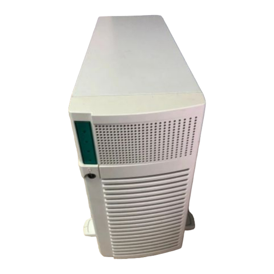
- Page 1 Intel SC5000 Server Chassis ® Subassembly Product Guide ® A Guide for Technically Qualified Assemblers of Intel Identified Subassemblies/Products Order Number: 744708-005...
- Page 2 Intel products are not designed, intended or authorized for use in any medical, life saving, or life sustaining applications or for any other application in which the failure of the Intel product could create a situation where personal injury or death may occur. Intel may make changes to specifications and product descriptions at any time, without notice.
-
Page 3: Table Of Contents
Contents 1 Chassis Description Kit Contents.......................... 7 Feature Summary......................... 7 Chassis Front Controls and Indicators ................. 8 Chassis Back I/O Ports and Features ................9 Chassis Side View ..................... 10 Peripherals ......................... 11 5.25-inch Removable Media Drive Bays ..............11 5.25-inch Hard Drive Bays .................. - Page 4 Extent of Limited Warranty ....................81 Warranty Limitations and Exclusions .................. 82 Limitations of Liability....................82 How to Obtain Warranty Service ..................83 Telephone Support ....................83 Returning a Defective Product ................... 84 Intel SC5000 Server Chassis Subassembly Product Guide...
- Page 5 Figures Screw Description......................7 Front Controls and Indicators ..................8 Back Controls and Indicators ..................9 Chassis Side View ..................... 10 Lock Loop........................13 Door Lock ........................13 Removing the Access Cover..................16 Installing the I/O Shield....................17 Rubber Bumper Placement ..................18 Installing the Server Board ..................
- Page 6 Intel SC5000 Server Chassis Subassembly Product Guide...
-
Page 7: Chassis Description
1 Chassis Description Kit Contents The SC5000 chassis subassembly kit includes this Product Guide; a power cord; two chassis feet; and a box that includes six 5.25-inch external drive rails and mounting screws (Figure 1, B), mounting screws for the chassis feet (Figure 1, D), mounting screws for the server board (Figure 1, C), and mounting screws for IDE drives (Figure 1, A). -
Page 8: Chassis Front Controls And Indicators
G. Internal drive bays H. Chassis intrusion switch Diskette drive bay; diskette drive shown installed* Reset button Power On/Off button Sleep button M. Security lock * Items shown may not be included in the chassis. Intel SC5000 Server Chassis Subassembly Product Guide... -
Page 9: Chassis Back I/O Ports And Features
Chassis Back I/O Ports and Features D C B OM09070 Figure 3. Back Controls and Indicators Expansion slot covers VGA monitor connector* C. Universal Serial Bus (USB) connectors D. NIC connector Serial port B, COM2 Parallel port G. Serial port A, COM1 H. -
Page 10: Chassis Side View
5.25-inch removable media drive bays Diskette drive* C. 5.25-inch hard drive bays D. Foam epac fan carrier Main chassis Server board* G. Power supply * Items shown may not be included in the chassis. Intel SC5000 Server Chassis Subassembly Product Guide... -
Page 11: Peripherals
The hot swap drive bay accepts 1-inch peripherals that consume up to 14 Watts of power. Drives must be specified to operate at a maximum ambient temperature of 50 ºC. Power Supply The SC5000 chassis comes with either a 300 watt power supply or a 350 watt 1+1 redundant power supply. Chassis Description... -
Page 12: Checking The Power Cords
BMC on the server board. Server management software can be programmed to respond to an intrusion by powering down or by locking the keyboard, for example. Intel SC5000 Server Chassis Subassembly Product Guide... -
Page 13: Mechanical Locks
Mechanical Locks A padlock loop on the rear of the chassis access cover can be used to prevent access to the internal of the chassis. A variety of lock sizes can be accommodated by the .270 diameter loop. The front bezel has a two position lock to prevent access to the hard drives and the interior of the chassis. - Page 14 Intel SC5000 Server Chassis Subassembly Product Guide...
-
Page 15: Setting Up The Chassis
2 Setting Up the Chassis This chapter describes how to set your server up for the first time. Tools and Supplies Needed • Phillips (cross head) screwdriver (#2 bit) • Antistatic wrist strap (recommended) • Needle-nosed pliers Safety: Before You Remove the Access Cover Before removing the access cover for any reason, observe these safety guidelines. -
Page 16: Remove The Access Cover
4. Pull the entire cover outward, straight away from the chassis, to disengage the rows of tabs from the notches in the top and bottom edges of the chassis. Set the cover aside. OM09083 Figure 7. Removing the Access Cover Intel SC5000 Server Chassis Subassembly Product Guide... -
Page 17: Install The I/O Shield
Install the I/O Shield NOTE An ATX 2.03-compliant I/O shield is provided with the server board. The shield is required by Electromagnetic Interference (EMI) regulations. It minimizes EMI and ensures proper cooling of the server. If the shield does not fit the chassis, obtain a properly sized shield from the chassis supplier. The shield fits the rectangular opening near the power supply in the back of the chassis. -
Page 18: Install The Server Board Bumpers
Install the Server Board Bumpers Peel the adhesive backing from three rubber bumpers; stick the bumpers to the chassis wall (see Figure 9, A). 4.0" 8.0" 6.0" 10.75" 3.25" OM10344 Figure 9. Rubber Bumper Placement Rubber bumper Intel SC5000 Server Chassis Subassembly Product Guide... -
Page 19: Install The Server Board
Install the Server Board See your server board manual and/or quick start guide for more information on how to install your server board, processors, and memory. NOTE You should install URMs and processors before installing the server board into the chassis. 1. -
Page 20: Installing The Server Board
OM09082 Figure 10. Installing the Server Board Chassis Serverboard C. I/O connectors D. Positioning standoffs Screw (6-32 hex head) Intel SC5000 Server Chassis Subassembly Product Guide... -
Page 21: Connect Cables To The Server Board
Connect Cables to the Server Board See your server board product guide or quick start guide for connector locations. 1. Connect the power cables to the board. a. 300 watt power supply: • The large plug labeled P1 plugs to the main power connector on the server board. •... -
Page 22: Install The Diskette Drive
1. Using a magnetic screwdriver, remove the two screws that hold the diskette drive carrier to the front of the chassis. 2. Slide the carrier towards the rear of the chassis, until it comes free. OM09177 Figure 11. Removing the Diskette Drive Carrier Intel SC5000 Server Chassis Subassembly Product Guide... -
Page 23: Installing The Diskette Drive Into The Drive Carrier
3. Remove the 3.5-inch diskette drive from its protective wrapper. Record the drive model and serial numbers in your equipment log. 4. Set any jumpers or switches according to the drive manufacturer’s instructions. 5. Slide the drive into the drive carrier component side down. OM09061 Figure 12. -
Page 24: Installing The Diskette Drive/Carrier Assembly
NOTE Do not connect the data or power cables at this point. OM09178 Figure 13. Installing the Diskette Drive/Carrier Assembly Data cable Power cable Intel SC5000 Server Chassis Subassembly Product Guide... -
Page 25: Hard Drives
Hard Drives Drive Cabling Considerations The cables that ship with the SC5000 chassis are prefolded to fit the chassis. To minimize the chance of damaging a cable, you should keep the cables folded correctly. The number of devices you can install depends on: •... -
Page 26: Installing A 5.25-Inch Removable Media Device
2. Remove the two screws that hold the shield in place. 3. Pull the shield out of the chassis. Save the shield for use if you remove the peripheral. OM09174 Figure 14. Removing EMI Shields Intel SC5000 Server Chassis Subassembly Product Guide... -
Page 27: Slide Rails
4. Remove the drive from its protective wrapper and place it on an antistatic surface. 5. Record the drive model and serial numbers in your equipment log. 6. Set any jumpers or switches on the drive according to the drive manufacturer’s instructions. 7. -
Page 28: Installing A Removable Media Device
10. Connect a power cable to the drive. If your chassis contains the 350 watt power supply, use the plugs labeled P2-P5. OM09072 Figure 16. Installing a Removable Media Device Removable media device Data cable C. Power cable Intel SC5000 Server Chassis Subassembly Product Guide... -
Page 29: Installing A 5.25-Inch Or 3.5-Inch Hard Drive
Installing a 5.25-inch or 3.5-inch Hard Drive Five (two if the optional hot swap drive bay is installed) 5.25-inch half-height bays provide space for hard drives. 1. If you haven’t already done so, remove the top piece of foam epac from the system fans. 2. -
Page 30: Attaching A Hard Drive To A Carrier
C. Screw (6-32 flat head) 9. Line up the screws holes in the carrier with the screw holes in the drive. 10. Using four screws of the appropriate size and length, attach the drive to the carrier. Intel SC5000 Server Chassis Subassembly Product Guide... -
Page 31: Installing A Carrier
OM09179 Figure 19. Installing a Carrier Data cable Power cable 11. Slide the carrier into the chassis. 12. Insert and tighten the screws removed in Step 1. 13. Attach data and power cables to the drive. You must use the power plugs labeled P6 and P7 to connect to drives in the bottom two carriers. -
Page 32: Hot-Swap Scsi Hard Disk Drives
Hot-Swap SCSI Hard Disk Drives The chassis may contain the optional hot swap drive bay and 5 drive carriers, but no hard disk drives. Refer to the Intel customer support website for a list of approved SCSI devices. CAUTION Electrostatic discharge (ESD) and ESD protection: ESD can damage disk drives, add-in boards, and other components. -
Page 33: Sca Hard Disk Drive And Hot Swap Drive Carrier
3. Remove the 3.5-inch hard drive from its wrapper and place it on an antistatic surface. 4. Record the drive model and serial number in your equipment log. 5. Orient the drive as shown in Figure 21. 6. Using the four screws removed earlier, attach the carrier to the drive. OM09080 Figure 21. -
Page 34: Inserting A Hot Swap Drive
8. Push the drive into the chassis until the tab (Figure 22, B) engages the hole in the drive bay (Figure 22, A). 9. Push the carrier handle up until the latch clicks. OM09089 Figure 22. Inserting a Hot Swap Drive Hole Intel SC5000 Server Chassis Subassembly Product Guide... -
Page 35: Installing An Add-In Board
Installing an Add-in Board You may want to install an operating system before installing any add-in cards. If so, skip this step and return to it when you are ready. CAUTIONS Do not overload the server board by installing add-in boards that draw excessive current. -
Page 36: Install The Upper Foam Epac
8. Lay the SCSI I2C and diskette drive data cables in this gap on the shoulder of the foam epac. 9. Being careful not to pinch the cables, tilt the foam epac back into place. Intel SC5000 Server Chassis Subassembly Product Guide... -
Page 37: Install The Access Cover
Install the Access Cover 1. Place the cover so the tabs go into the slots on the server. The cover should be flush against the chassis. 2. Slid the cover forward until it stops. 3. Tighten the two captive screws into the rear of the chassis. OM09170 Figure 24. -
Page 38: Install The Chassis Feet (Pedestal Mode)
3. You are now ready to attach a monitor, keyboard, and mouse to your server, and turn it on. OM09071 Figure 25. Installing the Chassis Feet Screw hole Chassis foot C. Screw (M4 round head) D. Workbench Intel SC5000 Server Chassis Subassembly Product Guide... -
Page 39: Working Inside Your Server
3 Working Inside Your Server This chapter describes how to replace components in your server after it has been set up. All references to top, sides, and directions in this chapter refer to a chassis in a pedestal mount. Tools and Supplies Needed •... -
Page 40: Replacing Fans
Replacing Fans The SC5000 chassis contains two replaceable system fans. The power supply fan(s) are not replaceable. Your replacement fan should be the same size and type as the fan you are removing. 1. Remove the access cover. -
Page 41: Replacing A Power Supply
Replacing a Power Supply WARNINGS Hazardous conditions, power supply: Hazardous voltage, current, and energy levels are present inside the power supply. There are no user-serviceable parts inside it; servicing should be done by technically qualified personnel. 350 Watt Hot Swap Power Supply Modules 1. -
Page 42: 350 Watt Ac Power Supply Housing
Screw locations Screw locations 7. Remove the power supply from the chassis. 8. Remove the two screws that hold the bracket to the power supply. 9. Remove the bracket from the power supply. Intel SC5000 Server Chassis Subassembly Product Guide... -
Page 43: Removing The 350 Watt Power Supply Bracket
OM09183 Figure 28. Removing the 350 Watt Power Supply Bracket 10. Place the bracket on the new power supply and attach it with the two screws removed earlier. 11. Install the new power supply into the chassis. 12. Insert and tighten the six screws (four at the rear, two at the fan end) that hold the power supply to the chassis. -
Page 44: 300 Watt Power Supply
9. Insert and tighten the four screws that hold the power supply/bracket to the chassis. 10. Connect the power cables to the server board and peripherals. 11. Replace the access cover. 12. Connect the A/C power to the power supply. Intel SC5000 Server Chassis Subassembly Product Guide... -
Page 45: Replacing The 300 Watt Ac Power Supply
OM10266 Figure 29. Replacing the 300 Watt AC Power Supply Screw locations Working Inside Your Server... -
Page 46: Replacing The Front Panel Board
7. Place the new front panel board in the chassis. 8. Insert and tighten the three screws removed earlier. 9. Re-connect the front panel board cables. 10. Replace the access cover. OM10265 Figure 30. Replacing the Front Panel Board Screw Intel SC5000 Server Chassis Subassembly Product Guide... -
Page 47: Replacing The Hot Swap Backplane And Saf-Te Card
Replacing the Hot Swap Backplane and SAF-TE Card 1. Open the access cover. 2. Remove the top part of the foam epac. 3. Remove all of the drive carriers from the hot swap bay. OM09087 Figure 31. Removing the Hot Swap Drive Carriers Working Inside Your Server... -
Page 48: Removing The Hot Swap Drive Bay
5. Disconnect the power cables and I2C cable from the hot swap bay. 6. Pull the hot swap bay half way out of the chassis. 7. Disconnect the SCSI cable from the bay. 8. Remove the hot swap bay from the chassis. Intel SC5000 Server Chassis Subassembly Product Guide... -
Page 49: Removing The Hot Swap Backplane
9. Remove and save the four screws that hold the backplane to the bay. OM09066 Figure 33. Removing the Hot Swap Backplane Hot swap bay Hot swap backplane C. Bracket D. Screw Working Inside Your Server... -
Page 50: Replacing The Hot Swap Backplane
10. Carefully pull the backplane straight out from the bay. The SAF-TE card is connected to the backplane and may get damaged if you don’t pull it straight out. OM09182 Figure 34. Replacing the Hot Swap Backplane Hot swap backplane Notch for SAF-TE card C. SAF-TE card Intel SC5000 Server Chassis Subassembly Product Guide... -
Page 51: Saf-Te Card And Hot Swap Backplane
11. If you are replacing the hot swap backplane, do the following: a. Remove the SAF-TE card from the old hot swap backplane. b. Plug the SAF-TE card into the new hot swap backplane. 12. If you are replacing the SAFE-TE card, do the following: a. - Page 52 Intel SC5000 Server Chassis Subassembly Product Guide...
-
Page 53: Technical Reference
4 Technical Reference Power Supply Specifications Input Voltages 300 watt power supply • 100-120 V∼ at 50/60 Hz; 4.6 A • 200-240 V∼ at 50/60 Hz; 2.3 A 350 watt 1+1 power supply • 100-120 V∼ at 50/60 Hz; 6 A •... -
Page 54: Environmental Specifications
The noise of the variable speed power supply fans will increase with temperature and power load. Your selection of peripherals may change the noise level. Electrostatic discharge (ESD) Tested to 15 kilovolts (kV); no component damage Intel SC5000 Server Chassis Subassembly Product Guide... -
Page 55: Regulatory Information
Regulatory Compliance The SC5000 chassis subassembly, when correctly integrated per this guide, complies with the following safety and electromagnetic compatibility (EMC) regulations. Safety Compliance •... -
Page 56: Regulatory Compliance Markings
Increase the separation between the equipment and the receiver. • Connect the equipment into an outlet on a circuit different from that to which the receiver is connected. • Consult the dealer or an experienced radio/TV technician for help. Intel SC5000 Server Chassis Subassembly Product Guide... -
Page 57: Ices-003 (Canada)
Any changes or modifications not expressly approved by the grantee of this device could void the user’s authority to operate the equipment. The customer is responsible for ensuring compliance of the modified product. Only peripherals (computer input/output devices, terminals, printers, etc.) that comply with FCC Class B limits may be attached to this computer product. -
Page 58: Bsmi (Taiwan)
The following warning is provided on the server board configuration label, which is provided with the Intel server board boxed product. There is insufficient space on the server board to place this label. Therefore, the label must be placed permanently on the inside of the chassis, as close to the battery as possible. -
Page 59: Equipment Rack Precautions
Equipment Rack Precautions WARNINGS : The equipment rack must be anchored to an NCHOR THE EQUIPMENT RACK unmovable support to prevent it from falling over when one or more servers are extended in front of it on slide assemblies. The equipment rack must be installed according to the manufacturer’s instructions. -
Page 60: Installation Safety Instructions
Information for configurations can be found on Intel’s Server Builder Website at http://channel.intel.com/go/serverbuilder. If you do not have access to Intel’s web address please contact your local Intel representative. - Page 61 • Peripheral storage devicesmust be UL recognized or UL listed accessory and TUV or VDE licensed. Maximum capacity for this chassis is 10 devices; maximum of any one device is 19W. Total server configuration is not to exceed maximum loading conditions of power supply.
- Page 62 Intel SC5000 Server Chassis Subassembly Product Guide...
-
Page 63: A Equipment Log And Worksheets Equipment Log
Equipment Log and Worksheets Equipment Log Use the blank equipment log provided here to record information about your server. You will need some of this information when you run the SSU. Item Manufacturer Name and Model Number Serial Number Date Installed Chassis Server board Processor speed... - Page 64 Equipment Log (continued) Item Manufacturer Name and Model Number Serial Number Date Installed Intel SC5000 Server Chassis Subassembly Product Guide...
-
Page 65: Current Usage
Current Usage 300 Watt Power Supply As an overall current usage limitation on the power subsystem, do not exceed a combined power output of 167 watts for the +5 V and +3.3 V outputs. Exceeding a combined 167 watts will overload the power subsystem and may cause the power supplies to overheat and malfunction. - Page 66 167 watts for the +5 V and +3.3 V outputs. Exceeding a combined 167 watts will overload the power subsystem and may cause the power supplies to overheat and malfunction. Intel SC5000 Server Chassis Subassembly Product Guide...
-
Page 67: 350 Watt Power Supply
350 Watt Power Supply As an overall current usage limitation on the power subsystem, do not exceed a combined power output of 195 watts for the +5 V and +3.3 V outputs. Exceeding a combined 195 watts will overload the power subsystem and may cause the power supplies to overheat and malfunction. Calculating Power Usage The total combined wattage for your configuration must be less than 350 watts. - Page 68 195 watts for the +5 V and +3.3 V outputs. Exceeding a combined 195 watts will overload the power subsystem and may cause the power supplies to overheat and malfunction. Intel SC5000 Server Chassis Subassembly Product Guide...
-
Page 69: B Warnings
B Warnings WARNING: English (US) AVERTISSEMENT: Français WARNUNG: Deutsch AVVERTENZA: Italiano ADVERTENCIAS: Español... -
Page 70: Warning: English (Us)
Attach the covers to the chassis with the screws removed earlier, and tighten them firmly. Insert and lock the padlock to the system to prevent unauthorized access inside the system. Connect all external cables and the AC power cord(s) to the system. continued Intel SC5000 Server Chassis Subassembly Product Guide... - Page 71 WARNING: English (continued) A microprocessor and heat sink may be hot if the system has been running. Also, there may be sharp pins and edges on some board and chassis parts. Contact should be made with care. Consider wearing protective gloves. Danger of explosion if the battery is incorrectly replaced.
-
Page 72: Avertissement: Français
Revissez solidement les panneaux du boîtier avec les vis retirées plus tôt. Remettez le cadenas en place et verrouillez-le afin de prévenir tout accès non autorisé à l’intérieur du système. Rebranchez tous les cordons d’alimentation c. a. et câbles externes au système. suite Intel SC5000 Server Chassis Subassembly Product Guide... - Page 73 AVERTISSEMENT: Français (suite) Le microprocesseur et le dissipateur de chaleur peuvent être chauds si le système a été sous tension. Faites également attention aux broches aiguës des cartes et aux bords tranchants du capot. Nous vous recommandons l’usage de gants de protection. Danger d’explosion si la batterie n’est pas remontée correctement.
-
Page 74: Warnung: Deutsch
Bringen Sie die Verschlußeinrichtung (Padlock) wieder an und schließen Sie diese, um ein unerlaubtes Öffnen des Systems zu verhindern. Schließen Sie alle externen Kabel und den AC Stromanschlußstecker Ihres Systems wieder an. Fortsetzung Intel SC5000 Server Chassis Subassembly Product Guide... - Page 75 WARNUNG: Deutsch (Fortsetzung) Der Mikroprozessor und der Kühler sind möglicherweise erhitzt, wenn das System in Betrieb ist. Außerdem können einige Platinen und Gehäuseteile scharfe Spitzen und Kanten aufweisen. Arbeiten an Platinen und Gehäuse sollten vorsichtig ausgeführt werden. Sie sollten Schutzhandschuhe tragen. Bei falschem Einsetzen einer neuen Batterie besteht Explosionsgefahr.
-
Page 76: Avvertenza: Italiano
Attaccare le coperture al telaio con le viti tolte in precedenza e avvitarle strettamente. Inserire e chiudere a chiave il lucchetto sul retro del sistema per impedire l’accesso non autorizzato al sistema. Ricollegare tutti i cavi esterni e le prolunghe AC del sistema. continua Intel SC5000 Server Chassis Subassembly Product Guide... - Page 77 AVVERTENZA: Italiano (continua) Se il sistema è stato a lungo in funzione, il microprocessore e il dissipatore di calore potrebbero essere surriscaldati. Fare attenzione alla presenza di piedini appuntiti e parti taglienti sulle schede e sul telaio. È consigliabile l’uso di guanti di protezione. Esiste il pericolo di un esplosione se la pila non viene sostituita in modo corretto.
-
Page 78: Advertencias: Español
Inserte el bloqueo de seguridad en el sistema y bloquéelo para impedir que pueda accederse al mismo sin autorización. Conecte todos los cables externos y los cables de alimentación CA al sistema. continúa Intel SC5000 Server Chassis Subassembly Product Guide... - Page 79 ADVERTENCIAS: Español (continúa) Si el sistema ha estado en funcionamiento, el microprocesador y el disipador de calor pueden estar aún calientes. También conviene tener en cuenta que en el chasis o en el tablero puede haber piezas cortantes o punzantes. Por ello, se recomienda precaución y el uso de guantes protectores.
- Page 80 Intel SC5000 Server Chassis Subassembly Product Guide...
-
Page 81: C Warranty
Product or to refund the then-current value of the Product. In no event will Intel be liable for any other costs associated with the replacement or repair of Product, including labor, installation or other costs incurred by buyer. -
Page 82: Warranty Limitations And Exclusions
Limitations of Liability Intel’s responsibility under this, or any other warranty, implied or expressed, is limited to repair, replacement or refund, as set forth above. These remedies are the sole and exclusive remedies for any breach of warranty. -
Page 83: How To Obtain Warranty Service
How to Obtain Warranty Service To obtain warranty service for this Product, you may contact Intel or your authorized distributor. North AmericaCall Intel at 1-800-628-8686 during the warranty period during normal business hours (pacific time), excluding holidays. Please be prepared to provide: (1) your name, address, and telephone numbers;... -
Page 84: Returning A Defective Product
If the customer support group verifies that your product is defective, you will receive a Return Material Authorization (RMA)number to place on the outer package of the product. Intel can not accept any product without an RMA number on the package.
Need help?
Do you have a question about the SC5000 and is the answer not in the manual?
Questions and answers