Table of Contents
Advertisement
Quick Links
Advertisement
Table of Contents

Related Manuals for Mitel SMB Controller


Summary of Contents for Mitel SMB Controller
- Page 1 MiVoice Office 400 System Manual for Mitel SMB Controller RELEASE 6.3 April 2021...
- Page 2 ). The information is subject to change without notice and should not be construed in any way as a commit- ment by Mitel or any of its affiliates or subsidiaries. Mitel and its affiliates and subsidiaries assume no responsibility for any errors or omissions in this document.
-
Page 3: Table Of Contents
Application interfaces ......27 Mitel Open Interfaces Platform ......27 Message and alarm systems . - Page 4 Cable cover set ........90 Mitel SMBC rack-mounting set ......90 Location requirements .
- Page 5 IP system phones ......147 Mitel 6800/6900 SIP phone series ....149 Standard SIP phones and standard SIP terminals .
- Page 6 Configuration .......160 SMB Controller Manager ......160 Network Interfaces for SIP Trunk .
- Page 7 Special functions ......204 Shutting down the SMB Controller ..... . 204 Reset the IP address data .
- Page 8 Digital and IP system phones ....260 Mitel DECT radio units ..... . . 261 Operation of digital system phones .
-
Page 9: Product And Safety Information
BOUT OICE FFICE HAPTER RODUCT AND AFETY NFORMATION Product and Safety Information Here you will find information relating to safety, data protection and legal matters besides product and documentation information. Please read through the product and safety information carefully. About MiVoice Office 400 Purpose and function MiVoice Office 400 is an open, modular and comprehensive communication solution for the business sector with several communication servers of different performance and expansion capacity, an extensive... -
Page 10: Safety Information
AFETY NFORMATION HAPTER RODUCT AND AFETY NFORMATION • Ensure that all end users have access to the user guides. Download the MiVoice Office 400 documents from the internet: from Document Center Safety Information Reference to hazards Hazard warnings are affixed whenever there is a risk that improper handling may put people at risk or cause damage to the MiVoice Office 400 product. -
Page 11: Data Protection
A UPS system has to be connected up-circuit to ensure an uninterruptible power source. Up to a specific performance limit a Mitel 470 communication server can also be powered redundantly using an auxiliary power supply. For more information please refer to your communication server's system manual. -
Page 12: About This Document
: In this document, it is presumed, that the Mitel SMB Controller is loaded with a MiVoice Office 400 NOTE application software. This assumption is always valid, even the expression Mitel SMB Controller, SMBC or communication server is used. - Page 13 : Additional information on the handling or alternative operation of equipment. See also Reference to other chapters within the document or to other documents. Mitel Advanced Intelligent Network Particularities that have to be observed in an AIN. References to the MiVoice Office 400 configuration tool WebAdmin...
-
Page 14: System Overview
VERVIEW System Overview This chapter provides a brief overview of the Mitel Small and Medium Business Controller (SMBC) loaded with the MiVoice Office 400 application software describing the installation versions, the positioning within the MiVoice Office 400 series and the networking possibilities. It also features the system phones, the applications and the application interfaces. -
Page 15: Installation Versions
Controller ships with a fitted CPU module, 6 analogue terminal interfaces and 4 Gbit-LAN connections. Installation versions The Mitel SMB Controller is suitable for both desktop installation, wall mounting and installation in a 19" rack. Covers for connecting cables and special installation covers for rack installation are available sepa- rately. -
Page 16: Networking Possibilities
MiVoice Office 400 communication platforms can be used to network up to 100 other Mitel systems or SIP-compatible third-party systems. All the main telephony features such as call number and name display, enquiry call, hold, brokering, call transfer and conference circuits are supported. -
Page 17: Mitel System Phones And Clients
Mitel system phones and clients Mitel system phones stand out by virtue of their high level of user convenience and their attractive design. The broad range of products ensures there is a suitable model for every use. - Page 18 ITEL SYSTEM PHONES AND CLIENTS HAPTER YSTEM VERVIEW Table 2.1:Mitel system phones and clients (Continued) (Sheet 2 of 2) MiVoice Office Web Application • Provides the best features of a business desk phone on your (MOWA) computer • Business voice features including transfer, group calling, and hunt groups •...
- Page 19 ITEL SYSTEM PHONES AND CLIENTS HAPTER YSTEM VERVIEW Table 2.2:Mitel 6900 SIP series SIP phones (Continued) (Sheet 2 of 3) • User-friendly registration, Mitel 6920 SIP: configuration and opera- • Corded speech optimized tion of system features handset through MiVoice Office •...
- Page 20 ITEL SYSTEM PHONES AND CLIENTS HAPTER YSTEM VERVIEW Table 2.2:Mitel 6900 SIP series SIP phones (Continued) (Sheet 3 of 3) • Wall mounting possible Mitel 6930 SIP and Mitel 6940 SIP: • Power over Ethernet • Cordless speech optimized handset •...
- Page 21 ITEL SYSTEM PHONES AND CLIENTS HAPTER YSTEM VERVIEW Table 2.3:Mitel 6800 SIP series SIP phones (Continued) (Sheet 2 of 3) • User-friendly registration, Mitel 6863 SIP: configura-tion and opera- • Integrated 10/100 Mbit tion of system features Ethernet switch for...
- Page 22 : The phones of the Mitel 6700 SIP series (Mitel 6730 SIP, Mitel 6731 SIP, Mitel 6735 SIP , Mitel NOTE 6737 SIP , Mitel 6739 SIP, Mitel 6753 SIP, Mitel 6755 SIP and Mitel 6757 SIP) are supported as before (not all system features can be used).
- Page 23 ITEL SYSTEM PHONES AND CLIENTS HAPTER YSTEM VERVIEW Table 2.4:IP system phones (softphones) and clients (Continued) (Sheet 2 of 3) • Autonomous and powerful, IP-based PC system phone with intuitive user interface • Can be used with headset or handset via PC audio interface, USB or Bluetooth •...
- Page 24 ITEL SYSTEM PHONES AND CLIENTS HAPTER YSTEM VERVIEW Table 2.4:IP system phones (softphones) and clients (Continued) (Sheet 3 of 3) • OIP client application for PC-based call management • Used in conjunction with a system phone • Graphical user interface with mouse and keyboard operation •...
- Page 25 All the system features can • Headset socket with DHSG be used standard • Excellent voice quality due • Integrated switch for to Mitel Hi-Q™ wideband connecting a PC audio technology MiVoice 5380: • Automatic update of the • Backlit display phone software •...
- Page 26 (can be used with Mitel SIP-DECT only). : The Mitel 610 DECT, Mitel 620 DECT, Mitel 630 DECT, Office 135/135pro and Office 160pro/Safe- NOTE guard/ATEX cordless system phones are supported as before (not all system features can be used).
-
Page 27: Various Phones, Terminals And Equipment
: The Aastra 1910 and Aastra 1930 analogue phones are still supported. NOTE Various phones, terminals and equipment Thanks to the use of international standards other clients, terminals and phones, Mitel and third-party, can be connected and operated on the communication server: •... -
Page 28: Solutions
The functions are operated using the Mitel 6940 SIP, Mitel 6873 SIP, MiVoice 5380 / 5380 IP reception phone or the web-based Mitel 400 Hospitality Manager application. Reduced hospitality functionality are also available on Mitel 6920 SIP, Mitel 6930 SIP, Mitel 6867 SIP and Mitel 6869 SIP phones. -
Page 29: Mitel Applications
PPLICATIONS AND APPLICATION INTERFACES HAPTER YSTEM VERVIEW Mitel Applications Table 2.9:Mitel applications (Sheet 1 of 5) Application Main features Mitel Dialer • Simple first party CTI application • Dial, answer, hang up • Integration in Outlook, Lync 2013 and Office 365 •... - Page 30 PPLICATIONS AND APPLICATION INTERFACES HAPTER YSTEM VERVIEW Table 2.9:Mitel applications (Continued) (Sheet 2 of 5) Mitel Open Interfaces Platform (OIP) • Application interface for deep integra- tion of applications by Mitel or other manufacturers (see Application inter- faces) • Easy to manage through an integrated web-based application •...
- Page 31 Audio, web and video conferences Mitel 400 CCS • Mitel 400 CCS is an additional applica- tion for the Mitel 400 Call Center, and provides statistics / reporting functions and agent monitoring (CCS = call centre supervision). The licensing of the appli- cation is made via OIP.
- Page 32 PPLICATIONS AND APPLICATION INTERFACES HAPTER YSTEM VERVIEW Table 2.9:Mitel applications (Continued) (Sheet 4 of 5) Mitel BusinessCTI • Powerful Unified Communications solu- tion • Presence management with calendar integration • Instant Messaging (chat), video, SMS and e-mail functions • Compatibility with the federation...
- Page 33 • The alarm can be set off via a nurse call or fire-alarm system (ESPA interface), via a key predefined on the Mitel DECT or system phone, an alert button, web client, or by calling the alarm server (audio guide), or via e-mail (subject line analysis).
- Page 34 • Integrated online help and configura- tion assistant • Integrated in the communication server software package Mitel 400 Hospitality Manager • Integrated web-based application used to operate functions in the hospitality sector • List view and floor-by-floor view of the rooms •...
-
Page 35: Application Interfaces
VERVIEW Application interfaces The most important interface for own and third-party applications is the interface of the Mitel Open Inter- faces Platform (OIP). This open interface allows the applications to be deeply integrated with telephony. Third-party applications can also be integrated on MiVoice Office 400 series systems via different inter- faces without OIP. - Page 36 OIP as call center The powerful Mitel 400 Call Center is an integral part of OIP and provides all the main features such as flexible routing algorithms (cyclical, linear, longest time available, CLIP-based, last agent), skill-based agent groups as well as an analysis of the call centre data (online and offline) with chart-based evaluation.
-
Page 37: Message And Alarm Systems
The Mitel Alarm Server is a flexible solution which can be used in all sectors to process and record alarms. It can be used, for instance, in old people's nursing homes and assisted-living homes, as well as in other different facilities such as hotels, industrial plants, shopping centres, schools or administrations. -
Page 38: Isdn Interface
PC and phone allocation is handled by the telephony server. The third-party CTI connection is effected via Ethernet using the Mitel Open Interfaces Platform (OIP). To this end the OIP is installed on the telephony server. Third-party connections via Ethernet with CSTA are also possible. -
Page 39: Configuration
Configuration is done through WebAdmin. The Mitel 6940 SIP, Mitel 6873 SIP, MiVoice 5380 / 5380 IP reception phone or the web-based Mitel 400 Hospitality Manager application is available to operate the functions. Reduced hospitality functionality are also available on Mitel 6920 SIP, Mitel 6930 SIP, Mitel 6867 SIP and Mitel 6869 SIP phones. -
Page 40: Connection Options
PPLICATIONS AND APPLICATION INTERFACES HAPTER YSTEM VERVIEW Connection options Figure 2.5: Overview of interfaces with possible terminal equipment... -
Page 41: Getting Started
Phillips screwdriver size #1 Plan and order Set up your MiVoice Office 400 project in Mitel CPQ first. As a result, you will obtain a list of needed components, a slot usage layout, a DSP configuration table and a licence overview. -
Page 42: Download Documents, System Software And Tools
Proceed as follows to organize all downloads in a common folder: Download the Documentation set from the Mitel document portal If your Mitel SMB Controller does not have internet access, download the latest MiVoice Office 400 application software (e.g. “mivo400-8923a0-r3.lib32_aarch64_ilp32.rpm”) and the SMB Controller system software (e.g. “Mitel-SMBC_Management-1.1.9.1_Helium.zip”) from into the folder named Mitel. -
Page 43: Put Into Operation
Start an IP scanner application (e.g. the FREEWARE “Advanced IP Scanner”) in order to locate the SMB Controller in the IP network. Find your SMB Controller in the list with the help of the MAC address. The MAC address is written on a label, stuck on the CPU module (format: 08000F - XXXXXX). - Page 44 : Usually this step is only necessary for new installations but may also be necessary after an update NOTE of the SMB Controller system software. Be sure to save the MiVoice Office 400 configuration data if there was already a MiVoice Office 400 application software installed.
- Page 45 : If your communication server has Internet access, you can choose to skip this step, because you NOTE can download the audio guide languages later from a Mitel FTP server through the Localization( =e6) view in WebAdmin.
- Page 46 The second page, Setting up the IP addressing, opens. Set the Gateway address and a Primary DNS server. : If you do not set these parameters, you cannot load audio guides or update Mitel SIP phone NOTE strings from the Mitel download server.
-
Page 47: Register And Connect The Phones
In this part of the procedure, for registering the phones, you pair the data instances with the physical phones. : Mitel SIP phones get their time and date from an NTP server. To ensure this, enable the NTP service NOTE in System / General ( =ty) and enter the IP address of the NTP server. -
Page 48: Make Further Configurations
PPLICATIONS AND APPLICATION INTERFACES HAPTER YSTEM VERVIEW : You will find the MAC address of your communication server in IP network / IP addressing ( =9g) of WebAdmin. Choose your communication server from the list, and when prompted, enter the Registration user name and the Registration password. -
Page 49: Expansion Stages And System Capacity
Mitel CPQ. This is transition session. Summary The expansion possibilities of the basic systems Mitel SMB Controller at a glance. The equipment is powered by an external power supply. The mounting options are described in the Chapter Fitting the communication server. -
Page 50: Interfaces, Display And Control Elements
ASIC SYSTEM HAPTER XPANSION TAGES AND YSTEM APACITY • CPU module on mainboard, fitted with a RAM module • Fitted fan • Power supply unit with power cord Interfaces, display and control elements The following mainboard interfaces can be accessed only when the housing cover of the communication server is open: Table 3.1:Mainboard... - Page 51 ASIC SYSTEM HAPTER XPANSION TAGES AND YSTEM APACITY 1. Only 1 interface (eth0) is usable for MiVoice Office 400 The diagram below shows the position of all the interfaces and slots on the mainboard display and control elements and on the front panel. Figure 3.2: Mainboard interfaces, display and control elements and front panel Legend:...
-
Page 52: Power Supply
DSP chips on the modules can also be configured (see Max. number of channels per DSP chip on SM-DSPX1 or SM-DSPX2 Mitel 6900 SIP series SIP phones). Fixed functions of the mainboard DSP The table below provides an overview of the fixed functions of the mainboard DSP. No licences or addi- tional hardware is required to use the functions. - Page 53 ASIC SYSTEM HAPTER XPANSION TAGES AND YSTEM APACITY Table 3.3:Fixed functions of the mainboard DSP (Continued) (Sheet 2 of 2) FSK receiver for CLIP detection on analogue network interfaces FSK transmitter for CLIP display on analogue terminals Total audio channels for basic voice mail (G.711) or auto attendant 1.
-
Page 54: Expansion With Cards And Modules
XPANSION WITH CARDS AND MODULES HAPTER XPANSION TAGES AND YSTEM APACITY Table 3.5:Selectable functions of the mainboard DSP DECT Remarks VoIP Audio Standard configuration G.711 VoIP channels only, two of them can be used licence-free. 1. Licences required (see also Licences) 2. -
Page 55: Dsp Modules
: Do not use the older DSP modules of type SM-DSP1 and SM-DSP2 as these modules are not NOTE supported with Mitel SMB Controller. Allocatable functions One or more functions can be allocated to the individual DSP chips on the DSP modules. For this the DSP chips have to be loaded with different firmware. - Page 56 The allocation is configurable (see Con- figuration of DSP chips). Announcement service and music on hold use their own resources. : On the Mitel SMBC communication server G.711 audio channels are always used for audio services. NOTE The Voice mail mode parameter can therefore not be changed for this system.
- Page 57 XPANSION WITH CARDS AND MODULES HAPTER XPANSION TAGES AND YSTEM APACITY Table 3.7:Required VoIP channels between two possible endpoints (Sheet 1 of 2)
- Page 58 Non-IP endpoints: IP endpoints • Analogue terminal (FXS) • IP system phone • Digital system terminal (DSI) • Mitel SIP terminal • DECT cordless phone (DSI) • Standard SIP terminal • ISDN phone (BRI-S) • DECT cordless phone via SIP-DECT •...
- Page 59 XPANSION WITH CARDS AND MODULES HAPTER XPANSION TAGES AND YSTEM APACITY Table 3.8:Integrated Standard Media Switch modes of operation (Continued) (Sheet 2 of 2) Secure G.711 Same as G.711 but with a more One VoIP Channels for Standard secure data transmission using Media Switch licence is required the SRTP protocol.
- Page 60 XPANSION WITH CARDS AND MODULES HAPTER XPANSION TAGES AND YSTEM APACITY Table 3.9:Reserving audio channels (Continued) (Sheet 2 of 2) Reserved for call recording Number of audio channels on this node that can be used exclusively for call recording. Reserved for announcements Number of audio channels on this node that can be used exclusively with audio file.
- Page 61 = G.711 or G.711/G.729 1 channel for Mitel 4152 channels for Mitel 1. Licence(s) required (see also Licences) 2. Of relevance only to certain countries such as Brazil Table 3.11:Max. number of channels per DSP chip on SM-DSPX1 or SM-DSPX2 (Sheet 1 of 2)
- Page 62 XPANSION WITH CARDS AND MODULES HAPTER XPANSION TAGES AND YSTEM APACITY Table 3.11:Max. number of channels per DSP chip on SM-DSPX1 or SM-DSPX2 (Continued) (Sheet 2 of 2) 5...10 Depends on the parameter VoIP mode: • G.711: 10 channels • Secure G.711: 7 chan- nels •...
-
Page 63: Call Charge Modules
XPANSION WITH CARDS AND MODULES HAPTER XPANSION TAGES AND YSTEM APACITY Call charge modules Interface cards Interface cards can be assigned to two categories: • Trunk cards These cards provide interfaces for connection to public dial-up networks or for networking systems to create a private telephony network. -
Page 64: Wiring Adapter
XPANSION WITH CARDS AND MODULES HAPTER XPANSION TAGES AND YSTEM APACITY Table 3.12:Trunk cards (Continued) (Sheet 2 of 2) TIC-1PRI 1 PRI-E1 • Contains 30 B channels • 10 B channels can be used licence-free • Not usable in USA/Canada for the public network TIC-4TS 3 BRI-S/T + 1 BRI-T... -
Page 65: System Capacity
YSTEM CAPACITY HAPTER XPANSION TAGES AND YSTEM APACITY Table 3.13:Wiring adapter (Continued) (Sheet 2 of 2) WA-TS0 TIC-4TS, TIC-2TS Included in the equipment supplied with the interface cards WA-TS1 TIC-4TS, TIC-2TS must be ordered separately Included in the equipment WA-2W TIC-4AB , TIC-2AB ETAB4,... -
Page 66: Media Resources
YSTEM CAPACITY HAPTER XPANSION TAGES AND YSTEM APACITY Table 3.14:MiVoice Office Mobile Application - required resource reservation and allocation CPU Average Utilization in % Network IO in Kbps R6.3 2.28 3860 MOMA Inter MOMA 7011 Internal MOMA Media resources General system capacity The number of slots, interface cards and system modules per communication server have already been mentioned in the previous chapters and are not listed separately in this chapter. - Page 67 YSTEM CAPACITY HAPTER XPANSION TAGES AND YSTEM APACITY Table 3.15:General system capacity (Continued) (Sheet 2 of 6) Nodes in a transparent network – (AIN) Nodes with SIP networking Users Terminals per user Simultaneous connections • Without IP and without DECT 35/38 250/250 (internal / external)
- Page 68 "normal" Members per user group "large" Abbreviated dialling numbers + 4000 4000 PISN users Operator keys per phone on Mitel 6800/6900 SIP Room keys on Mitel 6873 SIP Mitel 6940 SIP (inclusive expansion keypad) Line keys per key telephone (except Mitel 6800/6900 SIP) Line keys per key telephone on 2...12...
- Page 69 User accounts for user access control Authorization profiles for user accounts Log entries per user account First-party CTI users via LAN First-party CTI users via Mitel Dialer Third-party CTI interfaces Third-Party CTI interface (Basic, Standard) Groups, Agents (OIP Call centre)
- Page 70 Total call list entries 60000 60000 Configured keys 48000 48000 Busy lamp field keys on Mitel SIP 4000 4000 phones in total Busy lamp field keys per Mitel SIP phone Same users on busy lamp field...
-
Page 71: Terminals
(16/48), (14/56), (12/72), (10/100), (8/160), (6/240), (4/320), (2/400).Example: The following line keys are configured on different Mitel SIP phones: 8 keys for line 1, 14 keys for line 2, 10 keys for line 3, 10 keys for line 4. - Page 72 SB-8ANT radi o units DECT Cordless Mitel 610/61 phones 2 DECT Mitel 620/62 2 DECT Mitel 630/63 2 DECT Mitel 650 DE Office 135 Office 160 terminals Terminals on LAN interfaces (total) DHCP clients on the internal DHCP server...
- Page 73 MiVoice 2380 IP MiVoice 536 0 IP MiVoice 5361 IP MiVoice 5370 IP MiVoice 5380 IP IP operator Mitel 6930 SI consoles / IP operator Mitel 6940 SI applica-tions Mitel 6869 Mitel 6873 SI MiVoice 5380 IP MiVoice 156 Reception/Fr...
- Page 74 YSTEM CAPACITY HAPTER XPANSION TAGES AND YSTEM APACITY Table 3.16:Maximum number of terminals per system and interface (Continued) (Sheet 4 of 5) Mitel SIP-DECT Cordless phones Standard SIP terminals Mitel BluStar 8000i Mitel BluStar Softphones Mitel Mobile Client Controller CloudLink Gateway –...
-
Page 75: Terminal And Network Interfaces
YSTEM CAPACITY HAPTER XPANSION TAGES AND YSTEM APACITY Table 3.16:Maximum number of terminals per system and interface (Continued) (Sheet 5 of 5) Analogue, nationally approved terminals • Pulse dialling (PUL) • Frequency dialling (DTMF) • Radio units for cordless phones •... -
Page 76: Software Assurance
Use of the call manager software requires a licence. Additional licences are required in order to use a number of enhanced functions and protocols, to enable voice channels or to operate certain terminals. The Mitel CPQ application automatically plans the necessary licences, which are then enabled on the communication server using a licence file. -
Page 77: Description Of Available Licences
Satellites with an incorrect release licence change over to restricted operating mode af- ter thirty-six hours. Satellites without any release licence change over to restricted oper- ating mode after four hours. User • Users Mitel SMBC requires a User licence for each user in the system. - Page 78 • User On the SMBC, the first 10 users are covered with the "Mitel SMBC Base license". From the 11th us- er, an extra "User" license is required. A user with such a normal user license can have up to 16 terminals. Depending on the terminal type (example: Mitel SIP, MiVoice 2380 Softphone, MOMA,...), additional terminal licenses are required.
- Page 79 5361 IP, MiVoice 5370 IP and MiVoice 5380 IP. The licences are needed to register the terminals on the system. If the required licences are missing, the relevant event message is output on the sys- tem. The licences can also be used if the Mitel SIP Terminals licences are missing (but not the other way round).
- Page 80 : In an AIN the licence is always acquired on the Master. The licence allows the remote main- NOTE tenance of the AIN via any Mitel 415/430 node. Note that the master node can also be of Mitel SMBC, Mitel 470 or Virtual Appliance type.
- Page 81 • VoIP Channels for Standard Media Switch : This licence is required for Mitel 415/430, Mitel SMBC and Mitel 470 only. For Virtual Appli- NOTE ance, the VoIP channels of the integrated Mitel Media Server are made available and do not require any licences.
- Page 82 TAGES AND YSTEM APACITY : Mitel Advanced Intelligent Network: In an AIN all the SIP licences are always acquired for the NOTE Master. The number of licences determines the maximum number of simultaneously active voice channels, regardless of the nodes on which they are currently being used. Requirement: The media resources on each node must be available and allocated accordingly.
-
Page 83: Restricted Operating Mode
ATASpro Interface: Additional functions available like DECT localization, public emergency number called alarm, evacuation alarm, enhanced safeguard with alarm trigger, get rooms and room state. : If you use the Mitel Open Interfaces Platform, OIP takes the licences from the communication NOTE server. -
Page 84: Temporary Offline Licences
YSTEM CAPACITY HAPTER XPANSION TAGES AND YSTEM APACITY • Dialling by name is deactivated. • Functions cannot be invoked via the menu or function key (likewise no enquiry calls can be made). • The team keys do not work. • Functions codes are not carried out (except remote maintenance on/off). - Page 85 YSTEM CAPACITY HAPTER XPANSION TAGES AND YSTEM APACITY Table 3.18:Overview of licences (Continued) (Sheet 2 of 11) User Allows user Locked 1, 20, 50, In the AIN, – operation on 100 or 200 only on the SMBC. additional Master; users per otherwise licence.
- Page 86 YSTEM CAPACITY HAPTER XPANSION TAGES AND YSTEM APACITY Table 3.18:Overview of licences (Continued) (Sheet 3 of 11) Standard Licence bundle: 1 additional In the AIN, – UCC User user per only on the • 1 additional licence. Master; user otherwise •...
- Page 87 YSTEM CAPACITY HAPTER XPANSION TAGES AND YSTEM APACITY Table 3.18:Overview of licences (Continued) (Sheet 4 of 11) Premium Licence bundle: 1 additional In the AIN, – UCC User user per only on the • 1 additional licence. Master; user otherwise •...
- Page 88 3.18:Overview of licences (Continued) (Sheet 5 of 11) Mitel SIP Number of 1, 20 or 50 In the AIN, Terminals registered phones additional only on the of the Mitel Mitel SIP Master; 6800/6900 SIP phone per otherwise series licence per node.
- Page 89 YSTEM CAPACITY HAPTER XPANSION TAGES AND YSTEM APACITY Table 3.18:Overview of licences (Continued) (Sheet 6 of 11) Number of 1 additional In the AIN, Terminals registered standard SIP only on the standard SIP terminal per Master; terminals licence otherwise per node. Video Use of the video Additional...
- Page 90 Features Analogue Use of the Locked Enabled In the AIN, Modem modem only on the functionality on Master; an Mitel 415/430. otherwise per node. Secure VoIP Encrypted VoIP Non-en Encrypted Per node – – connections using crypted transmission SRTP and TLS.
- Page 91 3.18:Overview of licences (Continued) (Sheet 8 of 11) Mitel SMBC Allows the Restrict Unrestricted In the AIN, – Base operation of with up to only on the Mitel SMBC with 10 users Master; licence 10 users. No (also in a otherwise additional AIN). per node. licences needed for set-ting up a AIN.
- Page 92 – simultaneously additional only on the active, user-linked instances Master; Mitel Dialer per licence otherwise applications. per node. Hospitality Use of Mitel 400 Locked Enabled In the AIN, – Manager Hospitality only on the Manager Master; otherwise per node. Hospitality...
- Page 93 YSTEM CAPACITY HAPTER XPANSION TAGES AND YSTEM APACITY Table 3.18:Overview of licences (Continued) (Sheet 10 of 11) Mitel Basic licence: Locked Enabled In the AIN, OpenCount Prerequisite for only on the Basic all other Master; Package OpenCount otherwise licences. Enables per node.
-
Page 94: Power Supply Capacity
Restricted operating mode). 2. The licences can also be used if the Mitel SIP Terminals licences are missing. 3. This licence is not viewable in the licence overview in WebAdmin. 4. If Virtual Appliance is used as Master, the VoIP channels of the master node are made available without a licence from the integrated Mitel Media Server. -
Page 95: Supply Power Available For Terminals
OWER SUPPLY CAPACITY HAPTER XPANSION TAGES AND YSTEM APACITY Supply power available for terminals The 40/48 VDC power supply required for the connected terminals is rated for the power requirements of a typical system configuration. Table 3.19:Power output of the 40/48 VDC power supply Power output of the 40/48 VDC power supply Available power output 24 Watt... -
Page 96: Power Supply Per Terminal Interface
4. The value applies to each interface and to radio units with hardware version “-2”. The value per interface for radio units with hardware version “-1” is 150 mW lower. 5. The value depends greatly on the terminal type. : With the planning application Mitel CPQ the power supply available for terminals is checked auto- matically. Power supply per terminal interface The power supply per terminal interface is determined by the interface type. -
Page 97: Installation
NSTALLATION Installation This Chapter tells you how the SMB Controller can be installed and the conditions to be observed. It also includes the mounting into a 19” rack, the correct way to connect the earthing, and the power supply. Other topics described in this chapter comprise fitting with system modules, interface cards and the rele- vant wiring adapters. -
Page 98: Equipment Supplied
Product information Mounting options Mitel SMBC includes all the materials required for wall or desktop installation. Additional rack installation sets are required for a 19” rack installation. For wall mounting all the connecting cables can be concealed behind a cable cover. This set can be ordered as an option. -
Page 99: Safety Regulations
ITTING THE COMMUNICATION SERVER HAPTER NSTALLATION Table 4.1:Location requirements (Continued) (Sheet 2 of 2) • Do not position in strong electromagnetic fields of radiation(e.g.near x-ray equipment, welding equip- ment or similar). Heat dissipation • Do not place any objects on top of the communica- tion server. - Page 100 ITTING THE COMMUNICATION SERVER HAPTER NSTALLATION the cable cover and the possibility of suspending the communication server into and out of the wall-mounted screws. The two diagrams below illustrate the two wall-mounting possibilities. Figure 4.2: Minimum distances for wall mounting (front panel facing to the right) All dimensions in mm...
-
Page 101: Drilling Plan
ITTING THE COMMUNICATION SERVER HAPTER NSTALLATION Figure 4.3: Minimum distances for wall mounting (front panel facing downwards) All dimensions in mm Drilling plan The communication server is suspended into two pre-mounted wall screws using the suspension points in the housing base. Depending on the type of mounting, these are the suspension points marked under position A or B on the drilling plan. -
Page 102: Drilling Template
ITTING THE COMMUNICATION SERVER HAPTER NSTALLATION Figure 4.4: Drilling plan for wall mounting All dimensions in mm Drilling template The packaging box of the communication server can also be used for marking out the drill holes. To do so it is best to detach the part of the inner packaging box that contains the drill holes. : The holes on the cardboard box are not labelled. -
Page 103: Wall-Mounting Procedure
ITTING THE COMMUNICATION SERVER HAPTER NSTALLATION Figure 4.5: Drilling template Wall-mounting procedure Materials required: • Screw set for wall/desktop installation • 6 mm drill • Screwdriver To mount the communication server to the wall, proceed as follows: Using the drill template or the instructions on the drill plan to mark out the three drill holes. Make sure you observe the minimum distances to other objects, walls or ceilings as shown in Minimum distances for wall mounting (front panel facing to the right) -
Page 104: Desktop Installation
ITTING THE COMMUNICATION SERVER HAPTER NSTALLATION Shut down the communication server (see Shut-down mode) and disconnect it from the power supply. : Be sure to observe the Safety regulations. CAUTION Remove the housing cover. Connect the earthing (see Connecting the earthing wire). -
Page 105: Rack-Mounting Procedure
ITTING THE COMMUNICATION SERVER HAPTER NSTALLATION Figure 4.6: Placing two communication servers above each other inside a 19” rack Rack-mounting procedure Materials required: • Rack-mounting kit • Screw set for wall/desktop installation • Screwdriver To rack-mount a communication server proceed as follows: Pull off the screw covers on the left and right of the front panel. -
Page 106: Installing The Cable Cover
ITTING THE COMMUNICATION SERVER HAPTER NSTALLATION Secure the cage nuts in the appropriate positions in the rack’s fastening rails (see Placing two communication servers above each other inside a 19” rack). Secure the communication server to the rack’s fastening rails using the M6 screws, the plastic washers and the cage nuts. -
Page 107: Powering The Communication Server
OWERING THE COMMUNICATION SERVER HAPTER NSTALLATION Powering the communication server The communication server is powered as standard with 230 VAC or 115 VAC. To ensure that its operation is maintained even in the event of a mains outage, an external uninterruptible power supply (UPS) must be used. -
Page 108: Earthing And Protecting The Communication Server
Table 4.2:Maximum power requirements of the communication server (Continued) (Sheet 2 of 2) Mitel SMBC The battery capacity required [Ah] can be calculated using the battery voltage and the maximum bridging time. It is important to note that the battery must never be allowed to become completely discharged and that in typical conditions only approx. - Page 109 ARTHING AND PROTECTING THE COMMUNICATION SERVER HAPTER NSTALLATION Figure 4.10: Earthing connection Figure 4.11: Earthing of the communication server in the case of an indirect cabling and direct cabling : In the case of an indirection connection make sure that the communication server’s earthing wire NOTE does not form any earth loops with the earthed cable screenings of the installation cables leading up to the (main) distribution frame.
-
Page 110: Connecting The Cable Screening
QUIPPING THE ASIC YSTEM HAPTER NSTALLATION Connecting the cable screening When using shielded installation cables also use shielded RJ45 connectors. In this way the shielding of the installation cables is automatically connected with the housing of the communication server and there- fore with the building earth. -
Page 111: Fitting A Wiring Adapter
QUIPPING THE ASIC YSTEM HAPTER NSTALLATION Fit the corresponding wiring adapter (see Fitting a wiring adapter) into the appropriate wiring adapter slot WA1…WA4. Fit the housing cover. Reconnect the communication server to the power supply. Figure 4.13: Fitting an interface card Fitting a wiring adapter Wiring adapters are used to route the interfaces of the interface cards to the RJ45 sockets on the front panel and are fitted to slots WA1…WA4. - Page 112 QUIPPING THE ASIC YSTEM HAPTER NSTALLATION Table 4.3:Combinations of wiring adapters / interface cards (Continued) (Sheet 2 of 2) WA-TS1 SSTT TIC-4TS SSST TIC-4TS SSTT – – TIC-2TS SSST – – TIC-2TS ETAB4 – WA-2W EADP4 – – TIC-4FXO – –...
-
Page 113: Fitting Dsp Modules
QUIPPING THE ASIC YSTEM HAPTER NSTALLATION 7. Port 8 is also routed to X.4 NOTE • The arrows on the wiring adapters specify the plug-in orientation of the required port assignment. • Any incorrectly fitted or missing wiring adapters are signalled by a red flashing LED on the display after start-up (see Wiring Adapter Malfunction Mode). -
Page 114: Connecting The Communication Server
ONNECTING THE COMMUNICATION SERVER HAPTER NSTALLATION Connecting the communication server There are two possibilities for connection to the telephone network and the terminal-side cabling: • Direct connection • Indirect cabling via (main) distribution frame and any universal building cable installation (UBC) (see also Connecting to a UBC via a (main) distribution board (example) Connecting to a UBC via... -
Page 115: Connection Via Main Distribution Board
With terminal cards with 8 or more interfaces, some or all of the RJ45 sockets are assigned four-fold on the front panel of the Mitel SMBC. With this cable they can be connected without the use of a fan-out-panel (FOP). The cable is 6 m long and at one extremity has four RJ45 connectors on which all the pins are wired. - Page 116 ONNECTING THE COMMUNICATION SERVER HAPTER NSTALLATION Table 4.4:Schematic diagram of prefabricated system cable 4 x RJ45 x 8 Pin (Continued) (Sheet 2 of 2) white x.1a green x.1b turquoise x.2a violet x.2b white x.3a brown x.3b turquoise x.4a violet x.4b white x.1a grey...
- Page 117 ONNECTING THE COMMUNICATION SERVER HAPTER NSTALLATION • 2 network interfaces BRI-T or 2 terminal interfaces BRI-S or a combination thereof. • 10 terminal interfaces (DSI, FXS) or a combination thereof. : This cable cannot be used to connect PRI and Ethernet interfaces (see also Connection of PRI NOTE primary rate interface...
-
Page 118: Connection To A Universal Building Cable Installation (Ubc)
ONNECTING THE COMMUNICATION SERVER HAPTER NSTALLATION Table 4.5:Schematic diagram of prefabricated system cable 12 x RJ45 (Continued) (Sheet 2 of 2) white – grey – turquoise – violet – – blue – turquoise – violet – – orange – turquoise –... -
Page 119: Cabling Interfaces
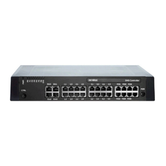
All the interfaces are routed to the front panel and are therefore accessible without opening the commu- nication server. Figure 4.18: Interfaces on the front panel with port designation (Mitel SMBC) Port addressing A port address is always of the type x.y. (x is the number of the card slot, and y, the port number.) -
Page 120: Network Interfaces
Equipping the system with interface cards provides the necessary network interfaces. With the exception of the Ethernet interface, which also represents a network interface via SIP access, there are no network interfaces on the Mitel SMBC mainboard. Basic rate interface BRI-T With the appropriate interface cards and wiring adapters, BRI network interfaces can be made available at RJ45 sockets 1.x...4.x.The possible RJ45 sockets are highlighted in colour in the figure below. - Page 121 ABLING INTERFACES HAPTER NSTALLATION BRI basic rate interface network-side Figure 4.20: Basic access on NT1 Do not connect power supply NT1 Do not fit the jumper The assignment of the RJ45 connector is identical on the NT-side and on the side of the communication server.
- Page 122 ABLING INTERFACES HAPTER NSTALLATION Basic access in the private leased-line network Figure 4.21: BRI-S basic rate interface external, networked with copper line Table 4.9:Connection of BRI-S basic rate interface external, networked with copper line PINX 1 signal Basic access Cable cores PINX 2 signal, Basic rate BRI-S ext.
-
Page 123: Primary Rate Interface Pri
ABLING INTERFACES HAPTER NSTALLATION Table 4.10:Cabling for basic rate interface BRI-T, networked with leased-line or dial-up connection (Continued) See also Chapter "Connections with basic accesses" in the PISN/QSIG Networking System Manual. Primary rate interface PRI NOTE • In normal operation the x.2 test socket must not be connected; otherwise faults may occur. •... - Page 124 ABLING INTERFACES HAPTER NSTALLATION PRI primary rate interface, network-side Figure 4.24: PRI primary rate interface on NT1 Table 4.12:Connection of PRI primary rate interface Cable Communication server coresStrai ght patch cable Socket PRI signal Socket signal – – – – –...
- Page 125 ABLING INTERFACES HAPTER NSTALLATION Primary rate access in the private leased-line network Figure 4.25: Primary rate access, networked with copper line Table 4.13:Cabling for primary rate access PRI, networked with copper line RJ45Pin PRI PINX 1 Cable cores Crossed PRI PINX 2 RJ45Pin signal patch cable...
- Page 126 ABLING INTERFACES HAPTER NSTALLATION Table 4.14:Cabling for primary rate access PRI, networked with transmission equipment RJ45Pi Cable Transm Transm Cable RJ45Pi PINX 1 cores, ission ission cores PINX 2 signal straight equip equip Straigh signal patch ment ment t patch cable signal signal...
-
Page 127: Fxo Network Interfaces
ABLING INTERFACES HAPTER NSTALLATION Table 4.15:Cabling for primary rate interface, PRI, networked with leased-line or dial-up connection (Continued) (Sheet 2 of 2) See also: System Manual “PISN / QSIG Networking” FXO network interfaces With the appropriate interface cards and wiring adapters, FXO network interfaces can be made available at RJ45 sockets 1.x...4.x. - Page 128 ABLING INTERFACES HAPTER NSTALLATION temperature is higher than normal and/or with a system with maximum configuration. Normally local exchanges produce a loop current of approx. 25 mA, which does not cause any restrictions. • Circuit type as per EN/IEC 60950: TNV-3 Connection Assignment of the RJ45 sockets on the front panel: Table...
- Page 129 ABLING INTERFACES HAPTER NSTALLATION Table 4.17:Connection of four-fold assigned FXO network interface (Continued) (Sheet 2 of 2)
-
Page 130: Terminal Interfaces
ABLING INTERFACES HAPTER NSTALLATION Cable Requirements Table 4.18:Cable requirements for FXO network interface Core pairs X cores 1 X 2 Stranded not required Wire diameter, core 0.4 … 0.8 mm Screening not required Resistance max. 2 X 250 W Terminal interfaces The number of available terminal interfaces on the mainboard can be increased by fitting interface cards. - Page 131 ABLING INTERFACES HAPTER NSTALLATION : It is possible to connect a DSI phone on the multiple assigned RJ45 sockets x.1 and x.2 directly NOTE without using a fan-out panel FOP. The following 2 ports are available in this case: Port 1 on x.1 and port 2 on x.2.
- Page 132 ABLING INTERFACES HAPTER NSTALLATION Table 4.20:Connection of four-fold assigned DSI terminal interface (Continued) (Sheet 2 of 2)
- Page 133 ABLING INTERFACES HAPTER NSTALLATION Depending on the line length, 1 or 2 phones can be connected on each DSI-AD2 interface. The following requirements apply with regard to the bus length to ensure that the maximum permissible signal delay is not exceeded: Table 4.21:DSI-AD2 bus length and number of phones Number of phones...
- Page 134 ABLING INTERFACES HAPTER NSTALLATION Table 4.22:Maximum power requirements of the system phones on the DSI bus (Continued) (Sheet 2 of 2) MiVoice 5380 DSI-AD2 interface 1340 MiVoice 5370, MiVoice 5380 DSI-AD2 interface with power supply unit Expansion key module MiVoice MiVoice 5370 M530 Expansion key module MiVoice...
- Page 135 ABLING INTERFACES HAPTER NSTALLATION Figure 4.32: Power available case A on the DSI-AD2 bus Power available case B: Applies to the SB-4+/SB-8 DECT radio units with hardware version "-2" and system phones of the Dialog 4200 series.
- Page 136 ABLING INTERFACES HAPTER NSTALLATION Figure 4.33: Power available case B on the DSI-AD2 bus NOTE • If another system phone is operated on the DSI-AD2 bus in addition to an MiVoice 5361, MiVoice 5370 or MiVoice 5380, at least one phone must be powered by a local power supply unit. •...
- Page 137 ABLING INTERFACES HAPTER NSTALLATION During start-up, these system phones carry out a detailed measurement of the available power. A warning is shown on the display if the result is inadequate: Line power too weak: External power supply required! NOTE • Depending on the power available based on the line length on the DSI-AD2 bus the ringing and hands-free volume decreases accordingly.
-
Page 138: Bri-S Terminal Interfaces
HAPTER NSTALLATION Installation rules • If a Mitel DECT radio unit is used, do not connect any other system phone to the same DSI bus. • Do not use any terminating resistors at the bus extremity. • Avoid using different cable cross-sections on the same bus •... - Page 139 ABLING INTERFACES HAPTER NSTALLATION Table 4.24:Connection of BRI-S terminal interfaces (Continued) (Sheet 2 of 2) – – – – – – – – S bus configuration The S bus is a four-wire, serial ISDN bus based on the DSS1 protocol (ETSI standard). It starts in each case at an BRI-S interface of the communication server.
- Page 140 ABLING INTERFACES HAPTER NSTALLATION Figure 4.36: S bus, short, V-shaped Figure 4.37: S bus, long Figure 4.38: S bus, point-to-point Greater distances (up to 8km) can be achieved using a standard commercial S bus extension. Restrictions The maximum number of terminals per S bus is further restricted by the power requirements of the termi- nals and their supplementary equipment: Table 4.26:Power balance on the S bus...
- Page 141 ABLING INTERFACES HAPTER NSTALLATION Connection sockets Figure 4.39: RJ45 connection, single socket Figure 4.40: RJ45 connection, double socket Installation rules : Circuit type as per EN/IEC 60950: SELV NOTE Always terminate the bus extremity with 2 ´ 100 W (0.25 W, 5%)!
-
Page 142: Fxs Terminal Interfaces
ABLING INTERFACES HAPTER NSTALLATION Cable Requirements Table 4.27:Requirements for an S bus cable Core pairs x cores 1 x 4 or 2 x 2 Stranded Wire diameter, core 0.4…0.6 mm Screening recommended Ohmic resistance lt; 98 W/km (conductor), lt; 196 W/km (loop) Characteristic impedance lt;... - Page 143 ABLING INTERFACES HAPTER NSTALLATION Table 4.28:Mode of the FXS interfaces (Continued) (Sheet 2 of 2) Phone/fax Analogue DTMF and pulse dialling terminals such as phones, fax, modem, answering machines, etc. 2-wire door Analogue two-wire door intercom External audio source Audio interface for connecting playback equipment with line output.
- Page 144 ABLING INTERFACES HAPTER NSTALLATION Ports FXS1...FXS6 on the mainboard are designed for long lines and support “High voltage” for the message LED. The no-load voltage at these ports is 48 VDC. The ports of interface cards (ETAB4) have a no-load voltage of 53 VDC. The loop current is lim-ited to 25 mA on all ports. Table 4.29:Cable requirements for FXS mode: Phone/fax Ports FXS1...FXS6...
- Page 145 ABLING INTERFACES HAPTER NSTALLATION Figure 4.44: Connection for FXS mode: 2-wire door Table 4.30:Cable requirements for FXS mode: 2-wire door Core pairs x cores 1 x 2 Stranded only with lengths > 200 m Wire diameter, core 0.4 … 0.8 mm FXS resistance max.
- Page 146 NSTALLATION NOTE • Only the FXS interfaces on the mainboard of the SMB Controller (FXS1...FXS6) support this feature. FXS interfaces on the card ETAB4 cannot be used. • The customer is responsible for all copyright matters relating to any music playback.
- Page 147 ABLING INTERFACES HAPTER NSTALLATION FXS mode: Control input If FXS interfaces are configured as control inputs, one or more of the switch groups can be switched between Positions 1, 2 and 3. An external switch or a relay is connected for this purpose. An LED can be connected to the circuit to indicate the switch state.
-
Page 148: Fan-Out Panel Fop
ABLING INTERFACES HAPTER NSTALLATION several devices connected in parallel) must not fall below 1 kW. The ringing voltage is 48 VAC. A 48 V relay must be interposed when connecting a large number of auxiliary bells. Figure 4.49: Connection for FXS mode: General bell See also "General bell on FXS interface"... - Page 149 ABLING INTERFACES HAPTER NSTALLATION Figure 4.51: Connection of four-fold assigned sockets via FOP connector strip The patch cables are available separately in lengths of 1 and 2 m (see Equipment Overview). The internal wiring of the fan-out panel is shown in the table below. The wiring is shown for sockets 1 - 4. Sockets 5 - 8 are wired accordingly.
- Page 150 ABLING INTERFACES HAPTER NSTALLATION Table 4.33:Wiring of sockets 1–4 in the fan-out panel FOP Socket The FOP fan-out-panel does not require a power supply...
-
Page 151: Ethernet Interfaces
NSTALLATION Ethernet interfaces The Mitel SMBC communication server has 4 GByte Ethernet interfaces permanently routed to the front panel and labelled accordingly. The RJ45 sockets are highlighted in colour in the figure below. : For the MiVoice Office 400 call manager software the interface eth0 must be used. The interfaces NOTE eth1...eth3 are used for multi-gateway functionality. - Page 152 Physical connection status of a network cable (Plugged or Unplugged) DHCP Click DHCP to address the SMB Controller through DHCP. If DHCP is disabled, the network parameters must be entered manually. For static addressing of the SMB Controller (recommended), enter a fixed IP address, subnet mask, and the IP address of the default gateway in the respective fields.
- Page 153 LAN cables can be used for all connection types. The Ethernet interfaces routed to the front panel can be configured individually in the network view of the SMB Controller Manager. Status LED The status of the Ethernet interfaces is indicated by the green and yellow LEDs directly on the interface in question.
-
Page 154: Multi-Gateways For Sip Trunks
ABLING INTERFACES HAPTER NSTALLATION Table 4.38:Status LED on the Ethernet interfaces (Continued) (Sheet 2 of 2) 1 Gbit/s Port has a connection with the network Flashing 10/100 Mbit/s Port is receiving or sending data 10/100 Mbit/s Port has a connection with the network Cable Requirements Use commercial Cat. -
Page 155: Installing, Powering, Connecting And Registering Terminals
NSTALLING POWERING CONNECTING AND REGISTERING TERMINALS HAPTER NSTALLATION Example: In the above figure, SIP Provider 1 and SIP Provider 2 are accessible via the dedicated DSL routers. The dotted path shows a call from the IP-Terminal via the dedicated router of the SIP Provider 2. All the other IP traffic, like general Internet traffic, is routed via the gateway of the default network interface. - Page 156 NSTALLING POWERING CONNECTING AND REGISTERING TERMINALS HAPTER NSTALLATION Table 4.40:Socket connections of the IP system phones of the MiVoice 5300 IP series (Continued) (Sheet 2 of 2) Socket connection for a workstation PC (integrated 100Base-T switch, available on MiVoice 5370 IP and MiVoice 5380 IP) Handset socket Headset socket...
-
Page 157: Mitel 6800/6900 Sip Phone Series
Mitel SIP phones are platform-independent phones with a wide range of features. They can also be perfectly integrated into one of the Mitel Platforms and used as a system phone. Mitel SIP Phones on MiVoice Office 400 first support MiVoice Office 400 features and have a separate user's guide. Many of the device-specific functions are less significant or are not used at all. -
Page 158: Standard Sip Phones And Standard Sip Terminals
System Manual "System Functions and Features". OIP and other applications Mitel Open Interfaces Platform (OIP) is also available as OIP Virtual Appliance and can be installed on the same server as the Virtual Appliance communication server. The operating requirements and instal- lation instructions for the OIP applications MiVoice 1560 PC Operator and Mitel OfficeSuite are described in the "Mitel Open Interfaces Platform"... -
Page 159: Digital System Phones
NSTALLING POWERING CONNECTING AND REGISTERING TERMINALS HAPTER NSTALLATION • TSD1 • TSD2 : In the following cases Not Configured is displayed along with the node number, the slot number NOTE and the port number. In this state the system phone is not ready for operation: –... -
Page 160: Mivoice 5361 / 5370/ 5380
NSTALLING POWERING CONNECTING AND REGISTERING TERMINALS HAPTER NSTALLATION : The total length of the cables from the communication server to the system phone must not be less NOTE than 10 m. Terminal selection Two system phones can be connected to a DSI interface (DSI-AD2 only). The system can only differen- tiate the two system phones by the position of the address switch on the phone. - Page 161 NSTALLING POWERING CONNECTING AND REGISTERING TERMINALS HAPTER NSTALLATION The MiVoice 5380 can also be equipped with a Bluetooth module as an option. To install (see Assembly module), proceed as follows: of the Bluetooth Figure 4.54: Assembly of the Bluetooth module : The system's reliability can be adversely affected by electrostatic discharges caused by touching CAUTION electronic components and elements, and subsequent damage can result.
-
Page 162: Dect Radio Units And Cordless Phones
NSTALLING POWERING CONNECTING AND REGISTERING TERMINALS HAPTER NSTALLATION • Terminal power supply of the communication server is overloaded Only use the corresponding plug-in power supply unit with FCC connector available as an option. It is connected either to the phone itself or, when using one or more expansion key modules, on the last expansion key module. -
Page 163: Installing The Radio Units
• Avoid exposure to chemicals. • Avoid direct sunlight. • See also technical data in Mitel DECT radio units. : If these requirements cannot be met (e.g.outdoor installation), use the appropriate protec- NOTE tive housing. Installing the radio units Do not remove the cover of the radio unit. (Warranty protection will lapse if the cover is removed) - Page 164 NSTALLING POWERING CONNECTING AND REGISTERING TERMINALS HAPTER NSTALLATION Figure 4.56: Installation distances [1] X = 200: Minimum distance if the radio units are connected to the same communication server (synchronous) X = 2000: Minimum distance if the radio units are not connected to the same communication server (not synchronous) Make sure the minimum distances are observed Connecting the radio unit...
-
Page 165: Analogue Phones Mitel 6710 Analogue, Mitel 6730 Analogue
As the DECT systems of the individual nodes in an AIN do not run synchronously, the two DSI interfaces of an SB-8 / SB-8ANT must always be connected to the same node. Table 4.46:Operating state display on Mitel DECT radio units LED flashing (two LEDs on the SB-8) Information... - Page 166 Tip for the setting polarity reversal: Set the switch of the phone (e. g. Mitel 6730 Analogue) to the symbol "−". If the MWI LED is blinking when a message is available and off when no message is available, the switch is set correctly. If the MWI LED is on when a message is available and blinking when no message is available the switch must be set to “+”.
- Page 167 If not, you can load the key configuration on the phone after connecting the phone, by clicking Update key configuration on phone. To load the key configuration on all connected Mitel 6700 Analogue series phones, click Update key configuration for all Mitel 6700 Analogue phones.
-
Page 168: Configuration
This chapter describes the web-based tool SMB Controller Manager, the web-based configuration tool WebAdmin as well as some additional options. With the SMB Controller Manager the installer sets some basic network configurations, can load a new SMB Controller software or call manager software and can execute some maintenance tasks. -
Page 169: Network Interfaces For Sip Trunk
HAPTER ONFIGURATION The SMB Controller Manager is included in the file system of each SMB Controller and is part of SMB Controller system software. Access: To access the login page of SMB Controller, enter the IP address of your SMB Controller including the port 8080 in your browser (Example: 10.100.98.50:8080). - Page 170 DMIN ONFIGURATION HAPTER ONFIGURATION Administrator authorization level: The Administrator has access to all the views and functions of the configuration tool (Expert mode). He can call up a set-up assistant, show a general configuration assistant and a special hospitality configura- tion assistant, and configure all system parameters.
-
Page 171: Integrated And Auxiliary Applications
The Hospitality Administrator features all the views required to set up the Mitel 400 Hospitality Manager and the reception menu of the Mitel 6940 SIP, Mitel 6873 SIP or MiVoice 5380 / 5380 IP and specify its default settings. A link can also be used to start the Mitel 400 Hospitality Manager (see... - Page 172 DMIN ONFIGURATION HAPTER ONFIGURATION Mitel 400 Hospitality Manager is integrated into WebAdmin and subject to a licence. Access: You have access to two types in Mitel 400 Hospitality Manager: • Register on the WebAdmin registration page with the access data of a user account to which an authorisation profile with the WebAdmin authorisation level has been assigned.
- Page 173 DMIN ONFIGURATION HAPTER ONFIGURATION Figure 5.4: Self Service Portal The Self Service Portal application is integrated into WebAdmin.
- Page 174 You can modify its IP address or directly start the WebAdmin administration tool. Moreover, with System Search you can load language files for the audio guide, Mitel phones as well as for the user interface and online help of WebAdmin, Hospitality Manager and Self Service Portal via MiVoice Office 400 FTP server onto your PC and upload them afterwards to the communication server with WebAdmin.
-
Page 175: Access Types With Smb Controller Manager
Self Service Portal user interfaces and online help. Access types with SMB Controller Manager Access the SMB Controller is only possible in the LAN with an Ethernet cable (directly or via a switch). External access with the SMB Controller Manager is not possible. -
Page 176: User Access Control
For the SMB Controller Manager there are two default user accounts. One account is for initial access, when the SMB Controller is started up and runs in normal mode. The other account is used when, for any reason, the SMB Controller software is not running correctly and the SMB Controller has to start up in... -
Page 177: Webadmin User Accounts And Authorization Profiles
User name admin Password admin : To prevent unauthorised access to the SMB Controller Manager, it is necessary to modify the NOTE default password during first access. Default user account in emergency mode To access the SMB Controller Manager in emergency mode enter the following: Table 5.2:Default user account in emergency mode... -
Page 178: Authorization Profiles
SER ACCESS CONTROL HAPTER ONFIGURATION Subject to the administration right for user access control, personal user accounts can be created in user access control ( =a7) and assigned some authorisation profiles. The following rules apply to user names selection and spelling: •... -
Page 179: Automatic Exit From The Configuration
The next time he logs in, the corresponding user is prompted to change the password and enter the new one he has been assigned. : For security reasons, there is no password-free access for the SMB Controller. Be careful with your NOTE passwords. -
Page 180: Webadmin Remote Access
In case of remote maintenance an entry will not be generated if remote maintenance is barred or if CLIP required is activated in the configuration and no CLIP is received. : There is no access log for the SMB Controller Manager. NOTE WebAdmin remote access With a remote maintenance access the user is authenticated using his user name and password. -
Page 181: Function Keys For Remote Maintenance Access
Remote maintenance access via an external dial-up connection to the AIN is also protected and has to be explicitly enabled via the control panel on the front panel (Mitel 470) or via the control key (Mitel 415/430). - Page 182 ONFIGURING WITH DMIN HAPTER ONFIGURATION The WebAdmin setup wizard takes you step by step through the setup of a basic configuration and is suit- able for initial communication server setup. The setup wizard is automatically called up when a new communication server is installed.
-
Page 183: Webadmin Configuration Notes
If we talk about file management we have to distinguish between the file management of the SMB Controller and the file management of the MiVoice Office 400 application. The file management of the SMB Controller is done via the SMB Controller Manager: •... -
Page 184: System Reset
Restart via front panel A direct restart via front panel is not possible. But you can execute a shut down of the SMB Controller using the pilot key. This closes all application in a controlled manner, enters shut-down mode for 1.5... -
Page 185: First Start
: This function is only accessible for Administrators in Expert mode. NOTE Factory Reset A factory reset of the SMB Controller is triggered in the SMB Controller Manager maintenance settings with the Factory reset button in the System reset view. NOTE •... -
Page 186: Data Backup
DMIN ONFIGURATION OTES HAPTER ONFIGURATION Data backup With a configuration data backup all the MiVoice Office 400 configuration data of the communication server is stored in a compressed file in ZIP format. You can let the configuration data backup run auto- matically (Auto backup) or as required (Manual backup). -
Page 187: Manual Backup
Before running a first-start of the communication server (a first start resets all the configuration data to their default values and deletes all audio data). • Before deleting the MiVoice Office 400 application from the Mitel SMB Controller or before you are resetting the Mitel SMB Controller to factory default values. •... -
Page 188: Mitel 6800/6900 Sip Phones
DDI numbers, CDE targets, user group entries, assigned phones, configured keys, etc. Mitel 6800/6900 SIP phones Prior to the registration, reset any phones that were already in operation back to the factory setting. For security reasons, delete the phone's MAC address in WebAdmin. -
Page 189: Operation And Maintenance
Memories on the CPU module of the SMB Controller System software When we talk about the system software we have to distinguish between the SMB Controller system soft- ware (based on Linux) and the MiVoice Office 400 application software, running in this Linux environment. -
Page 190: File System
Flash memory is decompressed, loaded into the main memory and started. File system When we talk about the file system, we have to distinguish between the SMB Controller file system (based on Linux) and the MiVoice Office 400 file system:... -
Page 191: Update Software
Update Software System software SMB Controller system software In some cases, it is necessary to reinstall the SMB Controller system software via the SMB Controller Manager (see Update the SMB Controller system software). If the SMB Controller Manager does not run anymore an Emergency Upload is required (see... - Page 192 Set the SMB Controller to emergency mode using the control key (see Emergency mode). : If an static IP address was set before, the SMB Controller should be reachable with the same IP NOTE address. Otherwise you have to find the IP address of the SMB Controller as described in chapter...
-
Page 193: Firmware For Corded System Phones
There is only one firmware for the cordless Mitel 600 DECT series phones. It is included in the MiVoice Office 400 application software package and stored in the file system of the communication server. -
Page 194: Firmware System Mitel Sip-Dect
VoIP devices on the LAN. OpenMobilityManager (OMM) is installed on one of the RFP radio units or on a PC, which constitutes the management interface for the Mitel SIP-DECT solution. Mitel 600 DECT phones have loaded a different firmware in an Mitel SIP-DECT system from the one in an MiVoice Office 400 DECT system. -
Page 195: System Information
Order the licences you want from your authorised dealer and specify the EID number, which serves to identify the communication server. The new licence file can be obtained either from your authorized dealer or via Mitel MiAccess https://miaccess.mitel.com/ using the EID (partner login required). -
Page 196: Replacing A Defective Interface Card
ARDWARE UPDATE HAPTER PERATION AND AINTENANCE Replacing a defective interface card A card is replaced by the same card type with the same number of ports. Procedure: : Be sure to observe the Safety regulations. CAUTION Carry out preparations (see Preparations Remove the housing cover. -
Page 197: New Card With More Ports
ARDWARE UPDATE HAPTER PERATION AND AINTENANCE New card with more ports A card is replaced by a similar card with more ports. Procedure: Change the card and put the system into operation again. Similar procedure as described in Replacing a defective interface card In the WebAdmin view Cards and modules (=4g) Confirm the new cards. -
Page 198: Changing The Dsp Module
ARDWARE UPDATE HAPTER PERATION AND AINTENANCE Changing the DSP module The following describes how to replace a DSP module if it is defective or how to replace it for another module type. To change a DSP module, proceed as follows: : Be sure to observe the Safety regulations. -
Page 199: Changing The Cpu Module
ARDWARE UPDATE HAPTER PERATION AND AINTENANCE Changing the CPU module The CPU module is fitted to the mainboard and is available as a spare part. If the com-ponents on the CPU module are defective or permanently faulty, the entire call manager card must be replaced. As a spare part the CPU module does not contain any RAM module or Flash card. -
Page 200: Replacing System Terminals
ARDWARE UPDATE HAPTER PERATION AND AINTENANCE : Be sure to observe the Safety regulations. CAUTION Back up the configuration data and audio data, if still possible. Carry out preparations (see Preparations). Remove the housing cover. Remove the interface cards (see Interface cards), the system modules (see System... - Page 201 In an operation with the card, the data stored on the card is always used. NOTE • The microSD card can only be used as from Device hardware 2 (concerns Mitel 620 DECT, Mitel 630 DECT). • Use the card only after reading this detailed description of the card functions. Failing to observe these recommendations may cancel the registration of operational devices.
- Page 202 : The protective cover should not be used for Mitel 620 DECT, Mitel 630 DECT with a white card NOTE holder or in Mitel 622 DECT, Mitel 632 DECT and Mitel 650 DECT. Insert the battery and cover the battery compartment.
-
Page 203: Display And Control Panel
→ After the target cordless phone is switched on again the copied user data is used. Display and control panel The display and control panel of the SMB Controller on the front panel consists of an LED display panel and a pilot key. It is used to indicate operating states and carry out functions. -
Page 204: Led Display
Warning / error The following display patterns and symbols have been defined for displaying an mode or an error of the SMB Controller or a running application (e.g. MiVoice Office 400): Table 6.4:Defined display patterns (Sheet 1 of 2) -
Page 205: Pilot Key (Ctrl)
Different actions are carried out depending on how long the key is pressed and the system’s current oper- ating mode. Operating modes For the SMB Controller we distinguish four operating modes. Table 6.5:Operating modes (Sheet 1 of 2) Operating mode... -
Page 206: Start-Up Mode
Start-up mode The start-up mode begins as soon as power is supplied or after a restart of the SMB Controller and ends when the SMB Controller enters normal mode. The LED combination patterns indicate the indi- [1]...[5]... -
Page 207: Normal Mode
MiVoice Office 400 WebAdmin. Normal mode The SMB Controller is in normal mode when the SMB Controller system software is up an running without error. The LED combination pattern is displayed. - Page 208 ISPLAY AND CONTROL PANEL HAPTER PERATION AND AINTENANCE If applications are loaded an running, there might be some additional information available, indicated with the LED F0 - F6. Each LED is assigned to an application. The F0 LED is assigned to the MiVoice Office 400 application: •...
-
Page 209: Emergency Mode
Emergency mode Whenever a standard software upload of the SMB Controller system software via the SMB Controller Manager is not possible or has proved faulty, you must carry out an emergency upload. For this purpose the SMB Controller must be set into the emergency mode. -
Page 210: Shut-Down Mode
This means, the applications need some time to save their data and to close. When the shut-down mode is reached, the SMB Controller will remain in this mode for 1.5 minutes before it starts up again automatically. During this period, the SMB Controller can be discon- nected from the power supply without concerns. - Page 211 – The F0 - F6 LED and the SYS LED are slowly flashing red to indicate the shut-down mode (pattern [17]). You can now disconnect the SMB Controller from the power supply without concerns within the next 1.5 minutes. Table 6.9:Enter shut-down mode (Sheet 1 of 2)
-
Page 212: Special Functions
Reset the IP address data The IP address data of the SMB Controller is stored in a flash chip and is retained, even after a first start of the MiVoice Office 400 call manager. The following sequence only resets the IP address data of the SMB Controller to the default values. -
Page 213: Carry Out A First Start Of Mivoice Office 400
Therefore, always back up the configuration data before a first start. The system-specific data such as the system ID, system type, sales channel, software generation and IP address of the system are preserved. Restart the SMB Controller with the Restart button in the SMB Controller Manager System reset view. –... - Page 214 The SMB Controller loads the system software and runs in normal mode. – The SMB Controller loads the MiVoice Office 400 application and a few seconds later you are able to reach the MiVoice Office 400 communication server showing the WebAdmin first access view.
-
Page 215: Operations Supervision
PERATIONS SUPERVISION HAPTER PERATION AND AINTENANCE Table 6.11:Carrying out a first start and reset sales channel (Continued) (Sheet 2 of 2) [25] Loadi Contr oller syste softw [26] Norm mode , SMB Contr oller is up runni Operations supervision Event message concept The system generates an event message every time an event or error occurs. -
Page 216: Event Types
PERATIONS SUPERVISION HAPTER PERATION AND AINTENANCE Event types Event messages have a certain severity level: Normal (blue), Serious (yellow) and Critical (red). Many event messages have both a negative impact (error occurred) and a positive impact (error corrected). Some event messages have no impact and, thus, no match. Severity level, positive or negative impact (if any) and the information, if there is a match or not, are indicated in the event table. - Page 217 Configuration template The missing configuration template Date, time Serious (positive, available for a Mitel SIP terminal is now with match) available in the communication server file system. Connection to IP IP remote management connection Cause, date,...
- Page 218 PERATIONS SUPERVISION HAPTER PERATION AND AINTENANCE Table 6.12:Event types, in alphabetical order (Continued) (Sheet 3 of 25) Connection to PMS A connection with a hotel Date, time critical (positive, system established management system (PMS system) with match) has now been successfully established.
- Page 219 PERATIONS SUPERVISION HAPTER PERATION AND AINTENANCE Table 6.12:Event types, in alphabetical order (Continued) (Sheet 4 of 25) CTI first party The first-party link was User number, critical (positive, Connection established (re-)established terminal ID, with match) protocol type (0=ATPC3, 1=CSTA) date, time CTI first party The first-party link was interrupted...
- Page 220 There are now enough licences Date, time Serious (positive, within the licence limit available for registering SIP phones with match) in the Mitel 6800/6900 SIP series on a backup communication server. : This event message is gener- NOTE ated by the backup communication server.
- Page 221 Date, time Serious (negative, power supply failed to the communication server has with match) (Mitel 470 only) failed. If the auxiliary power supply unit has been used for redundant operation, there are no short-term limitations. If the auxiliary power supply unit has been used to...
- Page 222 PERATIONS SUPERVISION HAPTER PERATION AND AINTENANCE Table 6.12:Event types, in alphabetical order (Continued) (Sheet 7 of 25) Fan failure (Mitel 470 The fan is jammed or defective or Parameter 1, critical (negative, only) the connection is no longer making parameter 2, with match) contact.
- Page 223 Slot number, Critical (without adapter (Mitel 415/430 wiring adapter slot or the wiring date, time match) and Mitel SMBC only) adapter fitted is unsuitable. Insufficient bandwidth An user in an AIN is trying to set up Link ID, WAN Serious (without...
- Page 224 PERATIONS SUPERVISION HAPTER PERATION AND AINTENANCE Table 6.12:Event types, in alphabetical order (Continued) (Sheet 9 of 25) IP address added to the A DoS attack has taken place IP address, Serious (negative, DoS black list beyond the maximum configured Cause (0: with match) admissible registration attempts or Registration /...
- Page 225 6.12:Event types, in alphabetical order (Continued) (Sheet 10 of 25) Language file The downloading of a language file Parameter 1: Serious (positive, download successful via FTP server for an Mitel SIP FTP server with match) terminal has been successfully address, completed.
- Page 226 PERATIONS SUPERVISION HAPTER PERATION AND AINTENANCE Table 6.12:Event types, in alphabetical order (Continued) (Sheet 11 of 25) Link to gateway The communication server has lost Number of critical (negative, satellite lost (Virtual the link to the gateway satellite. hours until with match) Appliance only) Without this link, the...
- Page 227 = 1: Terminal per user OK again reason = 2: MiCollab clients per user OK again Mitel Dialer within the Mitel Dialer user licences are now Date, time Serious (positive, licence limit again available again. with match) Mitel SIP terminals...
- Page 228 PERATIONS SUPERVISION HAPTER PERATION AND AINTENANCE Table 6.12:Event types, in alphabetical order (Continued) (Sheet 13 of 25) No DTMF receiver A permanent DTMF receiver (for BCS Ref., date, Serious (without available for integrated detection suffix dialling function time match) mobile/external codes) could not be assigned to an phones integrated mobile/external phone...
- Page 229 SMBC only) The appropriate measures must be date, time taken immediately to improve the heat dissipation, e.g. by providing the required clearances, lowering the ambient temperature or installing the fan from the rack-mounting set (Mitel 430 only).
- Page 230 Overload detected on A (current) overload was detected Date, time Normal (without USB port (CPU2) (Mitel on one of the USB interfaces on the match) 470 only) applications card (CPU2). : The maximum current input at NOTE the USB interfaces varies.
- Page 231 PERATIONS SUPERVISION HAPTER PERATION AND AINTENANCE Table 6.12:Event types, in alphabetical order (Continued) (Sheet 16 of 25) Port out of service A port previously in operation has Number of the Serious (without stopped func-tioning. slot, relevant match) port number, date, time Possible clone detected The clone detection service on the Date, time...
- Page 232 PERATIONS SUPERVISION HAPTER PERATION AND AINTENANCE Table 6.12:Event types, in alphabetical order (Continued) (Sheet 17 of 25) Restricted operating The communication server has Cause, date, critical (negative, mode enabled (Virtual switched to restricted mode. Cause: time with match) Appliance only) 0: No valid licence.
- Page 233 PERATIONS SUPERVISION HAPTER PERATION AND AINTENANCE Table 6.12:Event types, in alphabetical order (Continued) (Sheet 18 of 25) Software upgrade IP The software update of an MiVoice User number, critical (negative, system phone failed 5361 IP / 5370 IP / 5380 IP has terminal ID, with match) failed for the stated reason.
- Page 234 PERATIONS SUPERVISION HAPTER PERATION AND AINTENANCE Table 6.12:Event types, in alphabetical order (Continued) (Sheet 19 of 25) Standard SIP terminals SIP Terminals and Video Terminals Parameter Serious (positive, within the licence limit licences are now available. 1=1: SIP with match) again Terminals licence,...
- Page 235 PERATIONS SUPERVISION HAPTER PERATION AND AINTENANCE Table 6.12:Event types, in alphabetical order (Continued) (Sheet 20 of 25) Synchronisation with The primary communication server Backup critical (positive, backup communication was able (following one or more communica-tio with match) server successful previous failed attempts) to n server ID, transmit the configuration data to date, time...
- Page 236 The power supply to the terminals Date, time critical (positive, Within normal range is back in the normal rated output with match) again (Mitel 470 only) range following a slight, preceding overflow. Test event message The configuration of message Date, time...
- Page 237 : This event message is gener- NOTE ated by the backup communication server. The licence limit for Mitel Dialer could not be linked to a Total Serious (negative, Mitel Dialer has been user because too few licences are purchased...
- Page 238 Mitel, 1: 3rd expired (Critical severity level) and party), node ID needs to be renewed.If the or certificate endpoint type is = 0 (Mitel), then is name, date, param-eter 2 = node ID.If the time endpoint type is = 1 (3rd party),...
- Page 239 SIP endpoint was successfully endpoint (0: with match) renewed.If the endpoint type is = 0 Mitel, 1: 3rd (Mitel), then is parameter 2 = node party), node ID ID.If the endpoint type is = 1 (3rd or certificate party), then the remaining...
- Page 240 PERATIONS SUPERVISION HAPTER PERATION AND AINTENANCE Table 6.12:Event types, in alphabetical order (Continued) (Sheet 25 of 25) Too few VoIP channels An user is trying to set up a Available VoIP Normal (without connection that requires one or channels on match) more VoIP channels which are this node,...
- Page 241 PERATIONS SUPERVISION HAPTER PERATION AND AINTENANCE 1. The node is also always indicated in an AIN. Table 6.13:Meaning of the parameter values for the event message Send e-mail failed (Sheet 1 of 2) Parameter 1 (XXYY) Parameter 2: Parameter 3: Value Reason (XX) E-mail client...
-
Page 242: Event Tables
PERATIONS SUPERVISION HAPTER PERATION AND AINTENANCE Table 6.13:Meaning of the parameter values for the event message Send e-mail failed (Continued) (Sheet 2 of 2) E-mail text too User name long (body) authentica-tion (LOGIN) E-mail Password attachment too authentica-tion large (LOGIN) Format of e-mail Authentication attachment not... -
Page 243: Signal Destinations
PERATIONS SUPERVISION HAPTER PERATION AND AINTENANCE Table 6.14:Example of event table Event type Frequency Time period Total synchronization loss In this example an event message is sent to the message destinations if there is a Total synchronization loss event message when the system generates the event message 10 times within 1 hour. Signal destinations After a first start, all event tables are exactly assigned to a message destination. - Page 244 PERATIONS SUPERVISION HAPTER PERATION AND AINTENANCE Figure 6.7: Flowchart of the signalling of an event message to an external signal destination The following principles govern the way event messages are signalled to an external signal destination: • Individual event messages are not signalled if they occur at short intervals. The event messages are stored temporarily for 5 minutes and then sent together to the external signal destination.
- Page 245 Alliance - API and Interface Information - MiVoice Office 400 - MiVoice Office 400 Network Management. To access these documents, you have to be a member in Mitel Solution Alliance (MSA). If you are not a member yet, go to Mitel website and search for “Mitel Solution Alliance” where you can join. A member- ship on level MSA partner (MP) is sufficient.
- Page 246 Event messages can also be sent via the ATAS interface, for instance, to an alarm server. This may be an Mitel Alarm Server or a third-party alarm server. The use of the ATAS protocol is subject to a licence. After a first-start of the communication server, the signal destination Alarm server (ATAS) is automatically allocated event table 6.
-
Page 247: Operating State And Error Displays
PERATIONS SUPERVISION HAPTER PERATION AND AINTENANCE At least one event message is available and is hampering the system's function.(Example: Fan fail- ure) : Not all negative event messages have a positive match. In this case, the event messages must NOTE be confirmed manually in WebAdmin. -
Page 248: System Error Displays
• Check installation or connecting cable Operating state of the Mitel DECT radio units Each radio unit is equipped with 3 LEDs. The operating state the radio units is indi-cated by different colours and flashing sequences in cycles of 1 s, specifically by one of the two outer LEDs on the SB-4+ and by both outer LEDs on the SB-8 / SB-8ANT (separately for each DSI bus). - Page 249 PERATIONS SUPERVISION HAPTER PERATION AND AINTENANCE Table 6.16:Flashing sequences of the status LED on the DECT radio unit (Sheet 1 of 3) State Cycle Meanin flashing switche d off / softwar e not running / RU connec Error: DSI bus not in order Power...
- Page 250 PERATIONS SUPERVISION HAPTER PERATION AND AINTENANCE Table 6.16:Flashing sequences of the status LED on the DECT radio unit (Continued) (Sheet 2 of 3) Green / Startup process DSI ok Softwar e is upload Synchr onizing DECT is being started Power Down / DECT System...
- Page 251 PERATIONS SUPERVISION HAPTER PERATION AND AINTENANCE Table 6.16:Flashing sequences of the status LED on the DECT radio unit (Continued) (Sheet 3 of 3) Green Normal operati (requir ement: LED not switche d off): All B channe availabl 1 to 3 B channe ls busy channe...
-
Page 252: Malfunction Of The Mitel Dect Radio Unit
• LED of the radio units deactivated throughout the system Malfunctions of Mitel DECT cordless phones Table 6.18:Malfunctions of Mitel DECT cordless phones (Sheet 1 of 2) Error description Error cause / error handling No display. • Switch cordless phone on and test •... -
Page 253: Malfunctions Of The Dect Charging Bays
PERATIONS SUPERVISION HAPTER PERATION AND AINTENANCE Table 6.18:Malfunctions of Mitel DECT cordless phones (Continued) (Sheet 2 of 2) No dial tone. • Check radio units in this section Poor connection quality (echo effect). • Turn back loudspeaker opposite (for call parties) Cordless phone beeps approx. -
Page 254: Longclicks On Mitel Dect Cordless Phones
Check tone indicates correct contact. Longclicks on Mitel DECT cordless phones In normal DECT cordless phone operation, long-clicking the following keys accesses additional functions directly. Table 6.20:Longclicks on Mitel DECT cordless phones (Sheet 1 of 3) Function Office 135 Office 160 Mitel 600 DECT... - Page 255 PERATIONS SUPERVISION HAPTER PERATION AND AINTENANCE Table 6.20:Longclicks on Mitel DECT cordless phones (Continued) (Sheet 2 of 3) Indicates the cordless — phone’s internal diagnostics. Switches to a special — — alarm menu of the cordless phone. Indicates the data of —...
-
Page 256: Overload Code Displays Office 135 / Office 160
PERATIONS SUPERVISION HAPTER PERATION AND AINTENANCE Table 6.20:Longclicks on Mitel DECT cordless phones (Continued) (Sheet 3 of 3) Jumps to the cordless Loud-speaker key Loud-speaker key — phone’s tone ring menu. Menu for display — contrast, display backlighting, area tone and overload tone. -
Page 257: Other Aids
PERATIONS SUPERVISION HAPTER PERATION AND AINTENANCE Table 6.21:DECT overload code displays Office 135 (Continued) (Sheet 2 of 2) DL 04 Expiry Timer (on cordless Try again phone) has expired Timer Expired MM timer in system Try again has expired (during registration) Failure to set up traffic Connection cannot be... -
Page 258: Measuring Equipment For Cordless Systems
PERATIONS SUPERVISION HAPTER PERATION AND AINTENANCE : Be extremely careful while replacing or deleting files. The absence of files can hamper or even NOTE render impossible the working of the communication server. Measuring equipment for cordless systems The aids required for measuring out DECT systems are described under “Planning DECT Systems” in the User’s Guide. -
Page 259: Annex
YSTEMATIC DESIGNATION SYSTEM HAPTER NNEX Annex This chapter informs you about the systematic designation system and provides you with an equipment overview of the communication server with cards, modules and optional components. It also provides the technical data for interfaces, communication server and system terminals as well as a table overview of the digit key assignments and function keys for the system phones. -
Page 260: Rating Plate And Designation Stickers
PCB. • A change of version is effected following small changes to functions or once faults have been remedied. Backward compatibility is guaranteed. Rating Plate and Designation Stickers Figure 7.1: Rating plate Mitel SMBC communication server... -
Page 261: Equipment Overview
Designation stickers (example interface card) Equipment Overview Table 7.3:Equipment Overview Description Mitel SMB Controller, basic system with CPU module and power supply unit DSP module SM-DSPX1 DSP module SM-DSPX2 TIC-2AB trunk card (2 x FXO) TIC-4AB trunk card (4 x FXO) -
Page 262: Technical Data
Table 7.4:Overview of spare parts Description Mitel SMBC fan Mitel SMBC CPU module without DRAM Mitel SMBC 4GB DRAM module for CPU Power supply unit for basic system Two-pin standard power cable for basic system Technical data Network interfaces The following technical data applies to the network interfaces: Primary rate interface PRI •... -
Page 263: Terminal Interfaces
Ringing supply 40…43 V 50 Hz at load 4kW; no DC voltage overlay (country-specific versions also with 25 Hz) – No control key detection – No charge signalling pulses • For more technical details and cable requirements see Multifunctional FXS interfaces. Communication server Table 7.5:Ambient conditions (Sheet 1 of 2) Condition Mitel 415/430... - Page 264 Mitel 415 Mitel 430 Maximally configured approx. 37 W = 135 kJ/h approx. 50 W = 180 kJ/h system Table 7.8:Dimensions and weights Mitel SMBC for wall Mitel SMBC in rack mounting mounting Height 65 mm 65 mm Width 360 mm...
- Page 265 Control output on FXS no isolation interface Audio input no isolation Table 7.10:Ambient conditions Condition Mitel SMBC Ambient temperature 5 °C to 45 °C Relative air humidity 30 % to 80 %, non-condensating Table 7.11:Electrical data Mitel SMBC Class of protection Input voltage 95 V…253 V, 48…62 Hz...
-
Page 266: Design Of Interface Cards, Modules And Wiring Adapters
ECHNICAL DATA HAPTER NNEX Design of interface cards, modules and wiring adapters Table 7.13:Design Card/module Design TIC-4TS TIC-2TS TIC-4AB TIC-2AB TIC-1PRI EADP4 8DSI ETAB4 SM-DSPX1 SM-DSPX2 WA-TS0 WA-TS1 WA-2W WA-1PRI 1. Must not be used in USA/Canada. - Page 267 ECHNICAL DATA HAPTER NNEX Figure 7.3: Dimensions of interface cards (design A, B, C) Figure 7.4: Dimensions of system module (design D) Figure 7.5: Wiring adapter dimensions (design F)
-
Page 268: Lan Ports Eth0
DSI bus digital system phones Power see System Manual for "Mitel Advanced Intelligent Network (AIN) and IP consumption, IP system phones" system phones Table 7.15:Dimensions and weights, digital and IP system phones (Sheet 1 of 2) -
Page 269: Mitel Dect Radio Units
The following table contains the network features as defined in the GAP standard. For each feature a separate column indicates whether it is supported by communication servers of the MiVoice Office 400 family or Mitel DECT cordless phones. Table 7.16:Features supported as per GAP standard (Sheet 1 of 3) - Page 270 ECHNICAL DATA HAPTER NNEX Table 7.16:Features supported as per GAP standard (Continued) (Sheet 2 of 3) Go to DTMF signalling (defined tone length) Pause (dialling — pause) Incoming call Authenticatio n of PP Authenticatio — n of user Location registration On air key allocation Identification...
- Page 271 PP: Portable Part FP: Fixed Part M: Mandatory (this feature must be supported by GAP compliant equipment) O: optional —: The Mitel DECT cordless phones and MiVoice Office 400 communication servers do not support the feature. Technical data Table 7.17:Mitel DECT radio units (Sheet 1 of 2)
- Page 272 ECHNICAL DATA HAPTER NNEX Table 7.17:Mitel DECT radio units (Continued) (Sheet 2 of 2) Frequency range 1880 MHz to 1900 MHz Frequency bands (carrier) Channel spacing 1,728 MHz (carrier distance) Transmission rate 1152 kbit/s Duplex channels per 6 / 12...
-
Page 273: Operation Of Digital System Phones
PERATION OF DIGITAL SYSTEM PHONES HAPTER NNEX Operation of digital system phones Digit key assignment of system phones Digit key assignment depends on the system phones series and the language set for the communication server. The following Latin script assignment for the digit keys applies to the system phones MiVoice 5360 / 5360 IP, MiVoice 5361 / 5361 IP, MiVoice 5370 / 5370 IP, Office 135/135pro and all models of Office 160 for all communication server languages with the exception of Greek: Table... -
Page 274: Alpha Keyboard Mivoice 5380 / 5380 Ip
PERATION OF DIGITAL SYSTEM PHONES HAPTER NNEX Alpha keyboard MiVoice 5380 / 5380 IP The integrated alphanumerical keyboard on the MiVoice 5380 / 5380 IP is available in a QWERTY and AZERTY version. The special characters can be called up using the "Ctrl" key and the "Shift" key. Table 7.19:Integrated alphanumerical keyboard MiVoice 5380 / 5380 IP (Sheet 1 of 2) lt;Key>... -
Page 275: Function Commands (Macros)
End call and reseize line 1. Available only with the key telephones. 2. Available for Mitel 600 DECT only. The function commands can be stored directly on the system phones via Self Service Portal or on the function keys via WebAdmin. -
Page 276: Functions And Terminals No Longer Supported
Upload and the display of Virtual Appliance communication servers is not available. • The CPU2 application card is no longer supported (only CPU2-S). • The Telephony Web Portal (TWP) application is replaced with Mitel MiCollab Audio, Web and Video Conferencing. -
Page 277: Licensing Information Of Third-Party Software Products
ICENSING INFORMATION OF THIRD PARTY SOFTWARE PRODUCTS HAPTER NNEX Licensing information of third-party software products... -
Page 278: Documents And Online Help Systems With Further Information
MiVoice Office 400 Configuration Guide Mitel OpenCount for MiVoice Office 400 Installation and Administration Guide "Mitel Standard Linux" Solutions Guide "Virtual Appliance Deployment" Mitel SIP Teleworker via MBG on MiVoice Office 400 SMBC Manager Online Help WebAdmin Online Help Configuration assistant... - Page 279 System Manual for Mitel Advanced Intelligent Network (AIN) and IP sys-tem phones Private networking system manual Mitel SIP phones on MiVoice Office 400 Mitel 6730/31/53 SIP, Mitel 6735/37/55/57 SIP, Mitel 6739 SIP, Mitel 6863/65 SIP, Mitel 6867/69 SIP, Mitel 6873 SIP, Mitel 6920...
- Page 280 User's Guide MiVoice 1560 PC Operator Online Help Most of the documents are accessible at http://www.mitel.com/docfinder. Many documents in the above table are summarised per language and software release in documentation sets, and can be downloaded as a .zip file. Note: Documentation sets are very large (~500 MB). The download can take some time, depending on the connection.
Need help?
Do you have a question about the SMB Controller and is the answer not in the manual?
Questions and answers