
Related Manuals for Pylontech M1C-UL9540


Summary of Contents for Pylontech M1C-UL9540
- Page 1 M1C-UL9540 Integrated Outdoor Lithium Iron Phosphate Battery Energy Storage System User Manual This is an ANSI/CAN/UL9540 certified system.
-
Page 2: Table Of Contents
Table of Contents Safety ....................................1 1.1 Validity ....................................1 1.2 Target Group ..................................1 1.3 Safety Symbols Instructions ............................1 1.4 Safety of the Inverter ..............................1 1.4.1 Safety Instructions ..............................1 1.5 Safety of the System ..............................3 1.5.1 Safety Symbols ................................ - Page 3 3.1.1 External Dimensions ............................... 35 3.1.2 External Layout ................................. 36 3.1.3 Internal Layout ................................37 3.1.4 Installation Environment ............................38 3.1.5 Installation Clearance ............................. 38 3.1.6 Requirements of the installation foundation ....................40 3.1.7 Handling and installation of the cabinet ......................41 3.1.8 Cabinet Grounding ..............................
- Page 4 4.5.3.2 Replacement of Control Module (BMS) ......................89 4.5.4 Battery Maintenance ............................... 91 4.7 Emergency Disposal ..............................92 4.7.1 EPO (Emergency Power Off Switch) ......................... 92 4.7.2 Firefighting Equipment ............................92 5. Shipment and Storage ................................. 93 5.1 Shipment ..................................93 5.2 Storage ....................................
-
Page 5: Safety
1. Safety 1.1 Validity This document is valid for the Pylontech Outdoor Battery Cabinet. The system includes lithium iron phosphate battery modules, BMS, inverter, transformers, air conditioner, fire-fighting system, etc. 1.2 Target Group Outdoor Battery Cabinet is a high voltage energy storage system and can ONLY be operated by authorized personnel who must have following skills: ... - Page 6 Warning: The system must have Ground connections and Neutral connections. Ground MUST be bonded to Neutral ONLY ONCE in the circuit. Avertissement: Le système doit avoir des connexions à la terre et des connexions neutres. La terre DOIT être reliée au neutre UNE SEULE FOIS dans le circuit. Warning: Solar PV+/PV- are UNGROUNDED.
-
Page 7: Safety Of The System
1.5 Safety of the System 1.5.1 Safety Symbols Lethal voltage! Tension mortelle! Danger Battery strings will produce high voltage DC power and can cause a lethal voltage and an electric shock. La batterie produira un courant continu à haute tension et Danger peuvent provoquer une tension mortelle et un choc électrique. - Page 8 Warning electrical shock! Symbol Avertissement: choc électrique! in label More than one disconnect switch may be required to de-energize the equipment before servicing. Do not place near flammable material. Symbol in label Ne placez pas à proximité de matériaux inflammables. Do not connect the positive and negative reversely.
- Page 9 W arning: PowerCube-M1-C system working temperature range: 10°C~40°C; Optimum temperature: 18°C~28°C. The ambient temperature beyond the working temperature range may activate the battery system high/low temperature alarm or protection w hich further lead to the cycle life reduction as w ell. Besides, the extrem e working temperature will limit the warranty terms as well.
-
Page 10: Reference Standards
1.6 Reference standards 1.6.1 System Related Standards Description Code Safety Standard (US) UL9540 UN38.3 UN38.3 Safe Transport Standard UL EMC Standard 1.6.2 Battery Related Standards Description Code IEC62619 IEC63056 Safety Standard for Secondary Lithium IEC62477-1 Batteries IEC62040-1 UN38.3 Safe Transport Standard UN38.3 EN IEC 61000-6-1:2019 EN IEC 61000-6-2:2019... -
Page 11: System Introduction
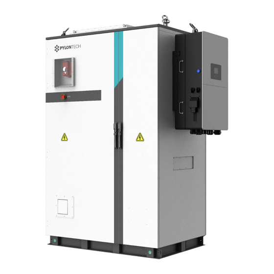
2. System Introduction Front View of the Cabinet Rear View of the Cabinet NOTE: The above pictures are for reference only, the appearance of the product is subject to the actual delivery. -
Page 12: Parameters Of The Outdoor Battery Cabinets
2.1 Parameters of the Outdoor Battery Cabinets 2.1.1 Parameters of 30kW system Optim US-Am-M1C-A- Optim US-Am-M1C-A- 30kW/xx -US-yy 30kW/xx -US-yy Specifications Model Name (10 batteries per one string, (11~14 batteries per one 1~4 strings parallel) string, 1~2 strings parallel) Rated Power(kW) Rated Output Voltage (VAC) AC side Max. - Page 13 Optim US-Am-M1C-A- Optim US-Am-M1C-A- 30kW/xx -US-yy 30kW/xx -US-yy Specifications Model Name (10 batteries per one string, (11~14 batteries per one 1~4 strings parallel) string, 1~2 strings parallel) 800 x m (BMS Qty.) + 43 x n (battery module Qty.) +80(PCS Weight (kg) weight) Cabinet installed on the ground (Applicable for hoist and...
-
Page 14: Parameters Of 60Kw System
2.1.2 Parameters of 60kW system Optim US-Am-M1C-A-60kW/xx -US-yy Specifications Model Name (14~21 batteries per one string, 1~2 strings parallel) Rated Power(kW) Rated Output Voltage (VAC) Max. output current(A) AC side Parameters Rated frequency (Hz) Wiring method Three-phase four wire +PE ON-Off Grid Switching Rated Power(kW) Max. - Page 15 System Configuration List-60kW Battery Rated Single String Energy Item Model String Voltage (Battery (firefighting Configuration (kWh) Qty. Energy) configuration) Optim US-A1-M1C- 66.3 A-60kW/ xx -US- yy 1 BMS + 14 battery modules Optim US-A2-M1C- 132.6 A-60kW/ xx -US- yy Optim US-A1-M1C- 71.0 A-60kW/ xx -US- yy 1 BMS + 15battery...
-
Page 16: System Diagram
2.2 System Diagram 2.2.1 Diagram for 30kW System... -
Page 17: Diagram For 60Kw System
2.2.2 Diagram for 60kW System... -
Page 18: Introduction Of The Inverter System
2.3 Introduction of the Inverter System 2.3.1 Products Descriptions Sol-Ark Series inverters are especially designed for commercial customers. The systems described in this manual include the following two types of inverters: • 30K-3P-208V • 60K-3P-480V The two model’s appearances look the same as follows. -
Page 19: Inverter Components (30K-3P-208V/60K-3P-480V)
2.3.1.1 Inverter Components (30K-3P-208V/60K-3P-480V) Inverter Indicators LCD Display (Touch) Function Buttons ON/OFF Button 2 x PV Disconnect Meter Port (optional) Parallel Port CAN Port Ground / Neutral Bars BMS Port RS485 Port Generator Input Grid Connection Function Port PV Input MPPTs Wi-Fi Interface Load Connection Battery Connections... -
Page 20: Packing List
2.3.2 Packing List 30K-3P-208/60K-3P-480 Packing list: Make sure the following items are included in your package: Model 30K-3P-208V 60K-3P-480V Sol-Ark 30K-3P-208V inverter (x 1) Sol-Ark 60K-3P-480V inverter (x 1) Mounting Bracket: For wall mounting the inverter (x 1) Bolts M12x60 (x 4) Bolts M4x12 (x 9) CAT 5 cable for parallel communications (x 2) WIFI Dongle: For software updates and remote monitoring (use M4x10 screws to hold in) -
Page 21: Specifications
2.3.3 Specifications 2.3.3.1 Parameters of the Inverter System Models 30K-3P-208V 60K-3P-480V 39,000 78,000 Solar Input power(W) Max Allowed PV Power (W) 39,000 78,000 Max PV Power delivered to Battery & AC outputs 30,000 60,000 Max DC Voltage (VOC) 500V@36A 1,000V@36A MPPT Voltage Range(V) 170~500 200~850... - Page 22 Models 30K-3P-208V 60K-3P-480V General Dimensions(H*W*D) 35.2*20.8*11.6(inch) 89.4*52.83*29.46(cm) Weight 172(lbs) 78(kg) Enclosure IP65/NEMA 3R Ambient Temperature(°C) * -40~60 Installation Style Wall-Mounted Wi-Fi & LAN Communication Included Standard Warranty (year) (verified by HALT Testing) Protections & Certifications of Inverter (30K-3P-208V/60K-3P-480V) Certifications Pending TÜV Rheinland Safety Standard UL1741-2021 3...
-
Page 23: Dimensions Of The Inverters
2.3.3.2 Dimensions of the Inverters Both the two model’s dimensions are the same as follows: 2” (5.08cm) 2” (5.08cm) 2” Minimum Horizontal Clearance | 6” Minimum Vertical Clearance Temperature Derating DC: 90C-100C Shutdown @ 100C AC: 75C-82C Shutdown @ 82C 2.3.3.3 Torque Values Application Note Model Sol-Ark 30K-3P-208V/ Sol-Ark 60K-3P-480V Load Terminal Block... -
Page 24: Wire Gauge Guide (Copper)
2.3.4 Wire Gauge Guide (Copper) PV input 12 - 10 AWG 34.93mm/ 50.8mm/ (1 3/8in) AC Inputs/Outputs 1/0 AWG - 4/0 AWG (2in) All Sensors 20 – 24 AWG CT Sensors 10' Wire Included Batt Temp Sensor 6' Wire Included RJ45 Cable 7' Included (Extendable up to 20') -
Page 25: Wiring Diagrams
PowerCube-M1-C, a high voltage battery storage system based on lithium iron phosphate battery, is one of the new energy storage products developed and produced by Pylontech. It can be used to provide reliable power for various types of equipment and systems. PowerCube-M1-C is especially suitable for application scene of high-power output, limited installation space, restricted load-bearing and long cycle life. - Page 26 Unpacking and check the Accessories Packing List: A. Internal Cable Kits for wiring connection up to Battery Controller Orange/0.19m/1/0AWG/ 2 (1) Power Cable + (Battery Module and Main Orange Terminal Controller Serial Connection) Black/0.32m/1/0AWG /2 Black (2) Power Cable - (Battery Module and Main Terminal Controller Serial Connection) Orange/0.24m/1/0AWG...
- Page 27 Black/0.5m/8 Core Super 5th (6) Battery Cascade Communication Cable Class Twisted-pair Wire/RJ45 (0.5m) B. External Cable Kit for wiring connection from Battery Controller to INVERTER/EMS/Power Supply NOTE External Cable Kits for wiring connection are available in four lengths,3.5m/5m/7m/10m. External Cable Kits is a separate kit externally from the battery or control module packaging. Orange/3.5m/1/0AWG/ Phoenix (1) External Power Cable+ Terminal/50-8 Terminal...
-
Page 28: Accessories Package List For 21 Pcs Of M1C Battery Modules [Complied With1Pc Of 60K-3P-480V Inverter (60Kw)] (For One String Only)
2.4.2.2 Accessories Package list for 21 pcs of M1C battery modules [complied with1pc of 60K-3P-480V Inverter (60KW)] (for one string only) C. Internal Cable Kits Item Description QTY. M1C Power Cable + (Battery Module and Main Controller Serial Connection) (0.19m) M1C Power Cable - (Battery Module and Main Controller Serial Connection) (0.32m) M1C Power Cable (Battery Module Upper and Lower Serial... -
Page 29: Parameters Of The Single Battery System
IP20 Cooling type Natural cooling Altitude [m] <2,000 UL1973, UL9540A, IEC62477-1, IEC62040-1, IEC62619, IEC63056, Certifications UKCA,CE LVD, CE EMC, UN38.3, VDE-AR-E 2510-50 *Cycle life is defined based on specific operation conditions, for more details please check with Pylontech service team. -
Page 30: Battery Module (H32148-C)
Dimension (W x D x H, mm) 330×628×150.5 Protection Class IP20 Weight (kg) Operation Cycle Life (cycle) 5,000 Operation Temperature(°C) 0~50 Storage Temperature(°C) -20~60 Transportation Certificate UN38.3 *Cycle life is defined based on specific operation conditions, for more details please check with Pylontech service team. -
Page 31: Front Interface Of The Battery Module
2.4.4.2 Front Interface of the Battery Module Power Terminals +/- Connect battery series power cables. Status Status LED shows the battery module’s status (Normal●, Abnormal●). Link Port 0, 1 Link Port 0, 1 Communication Terminal: (RJ45 port), CAN communication, between multiple serial battery modules and control module. -
Page 32: Control Module
2.4.5 Control Module SC 1000-200J-C 2.4.5.1 Parameters of the Control Module Product Type SC1000-200J-C Related Product M1-C AC Supply for BMS System Operation Voltage (VDC) 0~1000 Operation Current (Max.) (A) Self-consumption Power-Relay Off (W) Self-consumption Power-Relay On(W) Dimension (W*D*H, mm) 330×628×150.5 Communication MODBUS RTU\CAN\LAN... -
Page 33: Control Module (Sc1000-200J-C) Front Interface
2.4.5.2 Control Module (SC1000-200J-C) Front Interface External Pow er Term in als D+/D - Connect battery system with Inverter. Power Terminals B+/B- Connect battery power cables in series. 12VDC Out Power supply for MBMS, connects with MBMS’ 12VDC IN. 12VDC In In: Back-up 12VDC power supply port. - Page 34 Dry Contact Terminals Provides 2 input and 4 output dry contact signal. Reset Reset Button: Long press this button to restart the battery system. ADD: 6-bit dial switches to manually distribute the communication address of the battery system. Down position is OFF, means “0”. Upper position is ON, means “1”. 1st bit to 5th bits are for address, and the 6th bit dial switch supports a 120Ω...
- Page 35 Status LED Status light: to show the battery module’s status (RUN●, Alarm and Protection●). LED Status Indicators Battery capacity indicator: 4 green lamps, each light represents 25% capacity. LED Indicators Instructions LED Indicators Instructions STATUS STATUS Protection Capacity SOC (green) Battery (red) Descriptions...
-
Page 36: System Diagram
2.4.6 System Diagram 2.4.6.1 Multiple battery string in parallel connection by CAN communication between MBMS and BMS diagram (battery string qty. ≤6) 2.4.6.2 Multi battery string in parallel connection by Ethernet communication between MBMS and BMS diagram (battery string qty. ≤32 set) 2.4.6.3 Diagram between BMS and battery modules (internal power supply):... -
Page 37: Safety Features Installed With The System
2.5 Safety Features Installed with the System This system is equipped with the safety features, e.g. fire suppression system, smoke detector, temperature detector, gas detector, blow vent (air inlet vent and outlet vent), battery system over temperature protection, etc. When a fire or other emergency occurs or the temperature reaches certain point, aerosols will be released from the fire extinguisher to suppress the fire. -
Page 38: Fire Suppression System
2.5.1 Fire Suppression System The control logic of the fire suppression system is shown in the following diagram. Drawing of the external joint of water firefighting (unit: mm) -
Page 39: System Installation And Operation
3. System Installation and Operation 3.1 Outdoor battery cabinet layout 3.1.1 External Dimensions External dimensions are the same for both the 30 kW and 60 kW systems: Optim US-Am-M1C-A-30kW/xx-US-yy (10 batteries per one string, 1~4 strings parallel; where m = 1, 2, 3 or 4, xx=47, 94, 142,189, yy = 01, 02, 03, 04, or 05) Optim US-Am-M1C-A-30kW/xx-US-yy (11~14 batteries per one string, 1~2 strings parallel;... -
Page 40: External Layout
3.1.2 External Layout Explosion relief panel Sound-light Alarm Inverter Inverter HVAC (Air conditioner) Cabinet Front Door EPO (Emergency Power OFF witch) Air inlet Vent Right Side View Front View Cabinet Back door Air outlet Vent HVAC (Air conditioner) Water Sprinkler Inlet Rear View... -
Page 41: Internal Layout
3.1.3 Internal Layout Following is the layout of a 30Kw system with up to two BMS units and two battery strings. Other configurations can also refer to this drawing, only differs on the Qty. of BMS units and battery modules. MBMS BMS 2 BMS 1... -
Page 42: Installation Environment
3.1.4 Installation Environment The following requirements must be met for installation: • The IP rating of the outdoor cabinet is IP55, which meets the normal outdoor placement environment. And the standard anti-corrosion grade is C3H, so it is necessary to pay attention to stay away from high salt spray, high corrosion environment, away from heat sources and flammable and explosive materials. - Page 43 For the space requirements of one system with multiple cabinets, refer to the drawing below. 4. For the space requirements of multiple systems, refer to the drawing below.
-
Page 44: Requirements Of The Installation Foundation
3.1.6 Requirements of the installation foundation The installation foundation should be concrete or channel steel support structure, which should be flat, firm, safe and reliable. Uneven surfaces and depressions are strictly prohibited. The installation foundation must meet the following height requirements, whichever is higher: •... -
Page 45: Handling And Installation Of The Cabinet
3.1.7 Handling and installation of the cabinet • Outdoor battery cabinet needs to be handled by forklift or hoist lifting; When handling, move carefully to avoid impact or fall. • Keep the handling process slow and smooth. • During moving, the tilt angle of the device shall not exceed 15°, and it shall not be suddenly lowered or lifted. -
Page 46: Cabinet Grounding
3.1.8 Cabinet Grounding • PE (to the ground): Choose one of the four grounding points to connect the cabinet to the ground. (Grounding Screw specification: M10 x 30) Back Front • Grounding bar (electrical PE): Grounding cable(s) connected to grounding bar inside the cabinet. (Grounding Screw specification: M16 x16) -
Page 47: Installation And Operation Of The Inverter
3.2 Installation and Operation of the Inverter 3.2.1 Deciding the Site’s Backup Circuits Ensure you keep the Inverter within its amperage limits. • ON-Grid = 200A pass through (160A software limitation) • OFF-Grid = 30kW = 83.4A Continuous | 45kVA = 125A Peak (10s) Verify each load circuit by measuring typical and max Amps with a clip-on Amp meter. -
Page 48: Physical Installation (Small Commercial Backup)
3.2.4 Physical Installation (Small Commercial Backup) Use the output from 200A Fused Disconnect (from the grid) for the Grid input connection to the Sol-Ark. Connect the Load output from the Sol-Ark directly to the Main Service Panel (at least 2/0 AWG). Connect a Generator (150A @ 120V x3) or AC-Coupled system to the GEN terminal blocks. -
Page 49: Sensors Integration And Accessory Placement
Danger: Damage will occur if PV VOC > 500V. Danger: Des dommages se produiront si PV COV > 500 V. Parallel strings per MPPT must be the same Voltage. PV1 A/B must be the same voltage if using all two (2) strings. Arrays on the same MPPT CAN face different directions. - Page 50 Limiter Sensors (CT Sensors) [diagram to the right] • Install sensors on incoming electrical service wires L1, L2, & L3 (see Diagrams Section) • Limited Power to Home Mode (meter zero) and Peak Shaving Modes require CT sensors • To ensure the sensors will fit, please check the wire size before ordering (regular CTs accommodate up to 4/0 AWG) [Larger available: sales@sol-ark.com]...
-
Page 51: Powering-Up & Testing The Sol-Ark 30K-3P-208V
emergency stop pins that cut off the RSD power supply when triggered, thus stopping the inverter AC output. Pins 7 and 8 in the sensor pinboard 2 provide the 12V / 100mA signal power lost when the Sol-Ark shuts down using the front button. This diagram illustrates how to integrate the Tigo TS4-A- F and the corresponding... - Page 52 Measure L1/L2, L1/L3, L2/L3. Ensure 208 VAC Check Neutral and Ground are ~0 VAC Verify L1 voltage on AC in/out is 0 VAC with the main L1 connection in the panel. Same for L2 & L3 3. Check Battery Voltage Turn on the battery switch (if using a Lithium battery) Turn on the external battery disconnect The voltage should be nominal 300VDC [150VDC ~ 500 VDC]...
-
Page 53: Remote Monitoring Setup
3.2.6.1 Remote Monitoring Setup Ethernet Dongle A. Open the dongle (Black device) enclosure and thread the Ethernet cable through the hole and plug it into the RJ45 port. B. Reassemble the dongle housing, plug into the Sol-Ark, and secure it with screws (x2, M4x12) If all is well, you will see solid red and green lights. - Page 54 After filling the form, click “Create Account” 1. Add a Plant Scan the QR code on the dongle while plugged in. Make sure to pick a On Plant Type, ALWAYS unique plant name. (I.E. select Energy Storage Last Name, First four of (DC coupling).
- Page 55 3. Connect the System to the Internet If Wi-Fi paired with 10.10.10.1, select Done If Location Services are not enabled, it will be requested. Read and confirm conditions. Select Distribution Network to pair Dongle with WIFI Once you see this screen, go to your DEVICE’s Wi-Fi settings and connect to the Wi-Fi network that starts with:...
-
Page 56: Start Monitoring The Data
3.2.7.2 Start Monitoring the Data This screen is the real time view Alarms Graphed data System info and programming If you are installing parallel systems, DO NOT create a plant for each inverter. Create one plant for the Master unit and then use the browser version of Power View (mysol-ark.com). Click on the “…”... - Page 57 3. Select Your HOME Network Find the home network Enter personal Wi-Fi Password DO NOT SELECT DONGLE NETWORK Select "Connect" *Disclaimer* Connecting the dongle via the IP address only connects the dongle to the internet. *YOU MUST STILL CREATE AN ACCOUNT VIA THE POWER VIEW APP*...
-
Page 58: Gui Screens
4. Save Your Information If successful, you should see a Red and Green Light on the Dongle showing a successful connection. Red light may blink at a ~ 1s rate. LED: Connected to Sol- Ark and has power. Green LED: Connected to Internet and Server Flashing Green LED:... - Page 59 Basic Setup Limiter/Grid Setup...
-
Page 60: Programming Guide
3.2.7.5 Programming Guide 1. Sol-Ark Menus... - Page 61 2. Main Screens (Touchscreen) Detailed Volts View (Press Batt Icon) • Top row = Total power for the column • Solar Column: Displays voltage and amps per MPPT Danger: PV Voltage not to exceed 500V. Danger: Des dommages se produiront si PV COV >...
- Page 62 System Setup Menu ID = LCD serial #. Sol-Ark Technical Support uses the Wi-Fi serial #. COMM = LCD software version MCU = Inverter software version 3. Basic Setup Display Brightness adjustment Auto dim (must be enabled for the warranty to cover the LCD screen) Enable/disable BEEP Time Set the date and time for the system...
- Page 63 Use Batt V Charged: Displays battery charge and other system values in terms of voltage. Activate Battery 1&2: KEEP ON. This feature will help recover an overly discharged battery by slowly charging from the solar array or grid. Charge Float V: Set value according to the manual of the batteries connected to the system.
- Page 64 Solar Watts is for on Grid A. The system waits to turn on the smart load until enough PV power is produced (when on the grid) AC Coupling Settings (“For AC Coupled Input to Gen”) To use the Gen input terminal as an AC coupled input, check the "For AC Coupled Input to Gen" box (this feature will also work with three-phase "Grid-Tied"...
- Page 65 Power(W): Max watts called from the battery only at each time slot. Batt: The battery voltage or % at which the system will limit selling to the Grid or Home from the battery. The system will drain the battery until reaching that percent/voltage. Charge: Enables grid/gen charging up to the voltage or percentage specified on the line during a selected period.
- Page 66 Power source priority: Solar Panels | 2. Batteries (programmable % discharge) | 3. Grid (control when Grid charges) | 4. Generator Grid Selection Tab General Standard: uses Protect Parameters in table. UL 1741 & IEEE1547: Enables sell compliant functionality UL1741SA: Enables wider Freq, Voltage, and Power Factor Grid Frequency: Select the Grid Frequency connection.
-
Page 67: Limiter Sensors (Ct Sensors)
IP Tab HV1/HV2/HV3: Overvoltage protection point • 4.8s trip time LV1/LV2/LV3: Undervoltage protection point • 2.5s trip time HF1/HF2/HF3: Over frequency protection point • 4.8s trip time LF1/LF2/LF3: Under frequency protection point • 2.5s trip time F(W) Tab The Sol-Ark 30K-3P-208V can adjust the inverter output power according to the grid frequency. - Page 68 Transfer Switch, Knife Blade Disconnect, or Bypass Transfer Switch (upstream of Main Service Panel and Line-Side Tap). – see Diagrams Section Pgs. 8-17 2. CT Sensor Size • Each Inverter includes three (3) x 1 3/8” CT sensors (fits up to 4/0 AWG service wires and busbars) •...
-
Page 69: Installation Tips
Fig. In Limit d Po miter e Mod HM valu s S nso fa in ill b los to z . HM tion Sensors on th Fig. i (s) / input(s) S nso valu s should n no full los d on i (s) ati . -
Page 70: Grid-Tie / No Battery Install Tips
Auto Gen-start will be triggered when the battery voltage or percent reaches the level programmed in the Battery Setup menu. Then, the generator will continue to charge the batteries until they are about 95% full (this percentage is not programmable) before turning the generator off. We recommend changing the "Grid Reconnect Time"... -
Page 71: Installation And Operation Of The Battery System
3.3 Installation and Operation of the Battery System 3.3.1 Preparing tools and safety gear Danger: It is recommended to wear the following safety gear when dealing with the battery pack. Danger: Il est recommandé de porter l'équipement de sécurité suivant lors de l’opération de la batterie. -
Page 72: System Working Environments Checking
3.3.2 System Working Environments Checking 3.3.2.1 Cleaning Danger: The battery system has high voltage connectors. The clean condition benefits the isolation characteristic of the system. Danger: Le système de batterie a des connecteurs à haute tension. La condition de nettoyage entraînera la caractéristique d’isolation du système. Before installation and system working, the dust and iron scurf must be clean to ensure the environments cleaning. -
Page 73: Cables Connection
La salle doit être équipée d'un système de chauffage. Si la température ambiante est inférieure à 0°C, vous devez d'abord allumer le système de chauffage. Caution: Out of the working temperature range may cause reduction of the cycle of life of the battery even trigger the battery system over / low temperature alarm or protection. - Page 74 Caution: Wrong communication cables connection will cause the battery system failure. Attention,¤ Une mauvaise connexion des câbles de communication entraînera une défaillance du système de batterie. 3.3.4.1 Grounding Danger: The PowerCube-M1-C modules’ grounding is based on metal directly touch between the module’s surface and rack’s surface.
- Page 75 I. CAN Communication Mode between MBMS and BMS (battery string qty. ≤6 set) When system configured PowerCube-M1-C ≤6 set. The communication between PowerCube-M1-C uses CAN communication mode. The communication between the MBMS and the BMS of 1st PowerCube-M1-C uses CAN communication mode.
- Page 76 II. Ethernet communication between MBMS and BMS (battery string qty. ≤32 set). When system configured PowerCube-M1-C ≤32set. The communication between PowerCube- M1-Cs and MBMS uses Ethernet Switch by LAN communication. Relation of MBMS and battery strings (PowerCube-M1-Cs) in the ports of Ethernet Switch Both ends of BMS to MBMS communication cables must be marked with labels.
- Page 77 Caution: The last port of Ethernet Switch is for the MBMS. Attention: Les deux côtés du câble de communication de BMS à MBMS doivent être marqués avec des étiquettes. Caution: From the 1st port to the nth port are for the corresponding battery string (PowerCube-M1-C).
-
Page 78: Battery System Power On
3.3.4 Battery System Power On Warning: Double check all the power cables and communication cables. Make sure the voltage of the INVERTER is same level with the battery system. Check all the power switch of every battery system is OFF. Vérifiez deux fois tous les câbles d’alimentation et les câbles de communication. - Page 79 Press and hold the Start Button for more than 5 seconds until the buzzer rings, the LED indicator on front panel will light on if the start-up is successful. NOTE: Do not keep pressing the start button more than 30 seconds, or it will go into “BLACK- START” mode. System start process: The battery string’s system will check itself.
-
Page 80: Battery System Power Off
Si le "commutateur d’isolation" est éteint en fonctionnement normal, il doit d’abord éteindre le INVERTER. NOTE: After installation, do not forget to register online for full warranty: www.pylontech.com.cn/service/support. -
Page 81: Operation Of The Outdoor Battery Cabinet System
3.4 Operation of the Outdoor Battery Cabinet System 3.4.1 Outdoor battery cabinet system power on 1. Connect INVERTER external AC 480V power supply. 2. Connect external auxiliary power supply of AC277 V. And the transformer output is AC 220V. 3. Turn on the air-conditioning circuit breaker and air-conditioning starts working after self-check is completed. -
Page 82: System Debug And Maintenance
Do not dismantle the internal original components privately. At the end of the maintenance, count the tools and do not leave them in the cabinet. If you have any questions, please do not hesitate to contact PylonTech. 4.4 Maintenance Intervals Recommended Schedule of Routine Inspection... - Page 83 system. content of the environment in which it NOTE : The system must be powered off when cleaning dust. is used). (1) Check power cable connections for looseness and retighten to the torque specified above. Officially run for six Power circuit (2) Check power cables and control cables for damage, especially cut months, then every six connection...
-
Page 84: Inverter System Troubleshooting
(1) Check the stop function of the emergency stop button. Officially run for six (2) Simulate a shutdown and check shutdown signal communication. Safety months, then every year Functions (3) Check the body warning signs and other equipment markings and thereafter. - Page 85 DC Overload Fault • Check PV voltage • Make sure you have not wired more than two (2) solar strings in parallel System is beeping. • Check the system alarms menu to see which alarm has been triggered. Most alarms will self-reset •...
-
Page 86: Troubleshooting Phasing Issues
• If the AC Output Voltage is ~120V per leg (this is Wye configuration) and you have more than one Inverter in parallel, contact engineering support for further assistance. 4.4.2 Troubleshooting Phasing Issues. If the Sol-Ark screen shows Grid Phase Wrong, there is a phasing issue with your wiring, and it may cause overload faults (F18, F26, F34) and WILL CAUSE DAMAGE if left unchecked. - Page 87 Ground fault. Check PV+ or PV- wiring (which must be ungrounded). Exposed PV conductors + rain can also cause. Check GFCI_Failure that the neutral line and Ground are not double-bonded (common with portable generators). Overloaded the Load Output (reduce loads) or overloaded a generator (see the inverter separate manual for details).
-
Page 88: Battery System Debug And Maintenance
PV may be higher than 500V. Battery voltage should not be above DC_VoltHigh_Fault 500V (depending on the model). Batteries are overly discharged, the Inverter is off-grid and exceeds DC_VoltLow_Fault programmed batt discharge current by 20%, or Lithium BMS has shut down. If battery settings are incorrect, this can also happen. BMS communication Sol-Ark is programmed to BMS Lithium Battery Mode but cannot fault... -
Page 89: Trouble Shooting
PMU issue. Open BMS case, use multimeter check PMU 12Vdc output and CMU LEDs. If neither is on, please swap the PMU. Other error. 4. If problem remain, contact Pylontech service engineer. - Page 90 Section B During operation: (1) Error Code checked from BMS (Modbus protocol Appendix IV or CAN ID 0*4250&0*4290): *The ‘Failure Definition’ and ‘Failure Mode’ column is reference from Pylontech Modbus protocol Appendix IV Error code 1 bit to present. Failure...
- Page 91 Check the voltage sensor cable connect Sensor cable issue. between BMU and battery pack of the voltage sensor Sensor connection Hardware connectivity. error (Bit 0) issue Change the RED LED module. BMU issue 4. If problem remain, contact Pylontech service engineer.
-
Page 92: Replacement Of Main Component
4.5.3 Replacement of main component If the customer requires maintenance services, PylonTech may provide paid repair services as determined by the PylonTech's service organizations. When you need to repair or replace the main components of the product, please contact PylonTech in advance. -
Page 93: Replacement Of Control Module (Bms)
4. Dismantle the 4 screws of the battery module’s front face. 5. Handle the battery module out of the rack and put it to the appoint place. W arning: Single battery module weights 43kg. If without handling tools it must be handled by more than 3 personnel. - Page 94 Danger: the power cables still have high voltage DC power from another battery module, be careful to handle the Power plugs. Danger: Les câbles d'alimentation sont toujours alimentés en CC à haute tension par d'autres modules de batterie; vous devez manipuler les fiches d'alimentation avec soin. 3.
-
Page 95: Battery Maintenance
4.5.4 Battery Maintenance D a n g e r: The maintenance of battery must be done by qualified and authorized person only. Danger: La maintenance de la batterie doit être effectuée uniquement par le personnel qualifié et autorisé. Danger: Some maintenance items must shut off at first. Danger: Certains items de maintenance doivent être arrêtés en premier. -
Page 96: Emergency Disposal
4.7 Emergency Disposal 4.7.1 EPO (Emergency Power Off Switch) In case of fire or any situation beyond the control of anyone, please immediately snap the EPO button (as shown in the picture) to stop the system. DO NOT touch the EPO during normal operation. To restore the system, firstly rotate the EPO button in the operating direction on the panel to make the button pop up, and then power on the system according to the power on steps. -
Page 97: Shipment And Storage
5. Shipment and Storage 5.1 Shipment The outdoor battery cabinet is handled by forklift or hoisting. The outdoor battery cabinet is transported with battery. Therefore, ALWAYS avoid violent impact during handling. It should be fixed firmly during transportation, and no displacement is allowed in the carriage. ... -
Page 98: Annex 1: Diagrams Of 30K-3P-208V Inverter
Annex 1: Diagrams of 30K-3P-208V Inverter Diagram 1 ¤... - Page 99 Diagram 2...
- Page 100 Diagram 3...
- Page 101 Diagram 4...
- Page 102 Diagram ¤...
- Page 103 Diagram 6 ¤ Note: PV fuses are only required for >2 strings per MPPT...
- Page 104 Diagram 7...
- Page 105 Diagram 8...
- Page 106 Diagram 9 Note: Before powering up Parallel System installs, please see the inverter separate manual for details.
-
Page 107: Annex 2: Diagrams Of 60K-3P-480V Inverter
Annex 2: Diagrams of 60K-3P-480V Inverter Diagram 1... - Page 108 Diagram 2 CT Sensors are optional but necessary to enable Peak Shaving. (See the inverter separate manual for details.)
- Page 109 Diagram 3...
- Page 110 Diagram 4...
- Page 111 Diagram ¤...
- Page 112 Diagram 6...
- Page 113 Diagram 7...
- Page 114 Diagram 8...
- Page 115 Diagram 9...
-
Page 116: Annex 3: Cable Connection Diagram (Can ≤6 Set)
Annex 3: Cable connection diagram (CAN ≤6 set) -
Page 117: Annex 4: Cable Connection Diagram (Ethernet)
Annex 4: Cable connection diagram (Ethernet) -
Page 118: Annex 5: Installation And System Turn On Process List
Annex 5: Installation and System Turn ON Process List Tick after Item Remark completion The environment is meeting all technical requirements. 3.3.1 Cleaning 3.3.2 Temperature ☐ Refer to section 3.3.3 Radiating System 3.3.4 Heating System 3.3.5 Fire-extinguisher System 3.3.6 Grounding System ☐... - Page 119 Refer to section Double check every power cable, communication ☐ cables are installed well. And ADD Switches are setting 3.6.2.1 or 3.6.2.2 right. and 3.6.3. ☐ Check whether the UPS is turned on. And the UPS is Refer to section power supplying.
-
Page 120: Annex 6: System Turn Off Process List
Annex 6: System Turn OFF Process List Tick after Item Remark completion Turn off the switch between INVERTER and this Refer to section ☐ battery string (PowerCube-M1-C), or turn off the power switch of INVERTER, to make sure no current through 3.6.4. - Page 122 Pylon Technologies Co., Ltd. 5/F, No.71-72, Lane 887, ZuChongzhi Road, China (Shanghai) Pilot Free Trade Zone Pudong, Shanghai 201203, China T+86-21-51317699 | +86-21-51317698 service@pylontech.com.cn www.pylontech.com.cn...
Need help?
Do you have a question about the M1C-UL9540 and is the answer not in the manual?
Questions and answers