Pylontech PowerCube-X1 Operation Manual
Lithium-ion phosphate energy storage system
Hide thumbs
Also See for PowerCube-X1:
- Operation manual (44 pages) ,
- Operation manual (31 pages) ,
- Operation manual (31 pages)

Related Manuals for Pylontech PowerCube-X1


Summary of Contents for Pylontech PowerCube-X1
- Page 1 Lithium-Ion Phosphate Energy Storage System PowerCube-X1/X2 Operation Manual For UL version Information Version: 2.4 US20PIXV1001...
-
Page 3: Table Of Contents
This manual introduces PowerCube-X1/X2 from Pylontech. PowerCube-X1/X2 is a high voltage Lithium-Ion Phosphate Battery storage system. Please read this manual before you install the battery and follow the instruction carefully during the installation process. Any confusion, please contact Pylontech immediately for advice and clarification. - Page 4 3.6 Cables connection ......................21 3.6.1 Grounding connection: ..................... 21 3.6.2 Power and communication cable Connection ..........22 3.6.3 ADD Switch Setting (Address Assignment) ............24 3.6.3.1 Under communication for single BMS (battery string qty. 1 set) ....24 3.6.3.2 Under CAN Communication Mode between MBMS and BMS (battery string qty.
-
Page 5: Safety
Safety The PowerCube-X1/X2 is a high voltage DC system, operated by authorized person only. Read all safety instructions carefully prior to any work and observe them at all times when working on with the system. PowerCube-X1/X2 est un système à haute tension CC, opéré uniquement par le personnel autorisé. -
Page 6: Symbol In Label
Risk of battery system damage or personal injury Risque d'endommagement du système de batterie ou de blessure corporelle DO not pull out the connectors while the system is working! Warning NE PAS debrancher les connecteurs lorsque le système Avertisse fonctionne! ment De-energize from all multiple power sources and verify that... - Page 7 Do not place at the children and pet touchable area. Symbol Ne placez pas à la portée des enfants et des animaux in label domestiques. Symbol Recycle label. in label É tiquette de recyclage. Label for Waste Electrical and Electronic Equipment (WEEE) Symbol Directive (2012/19/EU) in label...
- Page 8 It will affect the warranty terms as well. Plage de température de fonctionnement du système PowerCube-X1/X2: 0° C – 50° C ; température optimale: 18° C-28° C. En dehors de la plage de température de fonctionnement, la batterie risque de réduire sa durée de vie et même l'alarme de...
- Page 9 1.2 Reference standards Description Code Safety standard for IEC62619 secondary lithium batteries UN38.3 Safe transport UN38.3 standard EN IEC 61000-6-1:2019 EN IEC 61000-6-2:2019 EN 61000-6-3:2007+A1 CE EMC StandardCE EMC EN 61000-6-4:2007+A1 Directive 2014/30/EU IEC 61000-6-1:2016 IEC 61000-6-2:2016 IEC 61000-6-3:2006+A1 IEC 61000-6-4:2018 Battery Cell safety standard UL1642 Battery Cell safety standard...
-
Page 10: System Introduction
PowerCube-X1/X2 is a high voltage battery storage system based on lithium iron phosphate battery, which is one of the new energy storage products developed and produced by Pylontech. It can be used to support reliable power for various types of equipment and systems. PowerCube-X1/X2 is especially suitable for those application scenes which required high power output, limited installation space, restricted load-bearing and long cycle life. -
Page 11: The Parameter Of System
2.2.1 The parameter of system PowerCube-X1-48/zzzV PowerCube-X2-48/zzzV Product Type (zzz=96~528, in step of 48) (zzz=96~528, in step of 48) LFP Lithium Ion Energy Storage LFP Lithium Ion Energy Product Name System Storage System Cell Technology Li-ion(LFP) Li-ion(LFP) 2.4 × n 3.552 ×... -
Page 12: Battery Module (H48050, H48074)
Operation Cycle Life 5,000 5,000 Operation Life(Years) Cooling Type Nature Nature Operation Temperature(℃) 0~50℃ 0~50℃ Storage Temperature(℃) -20~60℃ -20~60℃ Humidity 5~95% 5~95% UL1973, IEC62619 , UL1973, IEC62619 , Product Certificate CE EMC, IEC62477-1, CE EMC, IEC62477-1 Transfer Certificate UN38.3 UN38.3 Other: 1)Battery Controller 442*390*176... - Page 13 Product Type H48074 Cell Technology Li-iron(LFP) Battery Module Capacity(kWh) 3.552 Battery Module Voltage(Vdc) Battery Module Capacity(AH) Battery Module Charge Voltage(Vdc) Battery Module Charge/Discharge Current(Standard)(A) 14.8 Battery Module Charge/Discharge Current(Normal)(A) Battery Module Charge/Discharge Current(Max.)(A) Battery Module Discharge Voltage(Vdc) 43.5 Dimension(W*D*H, mm) 442*390*132 Communication RS232\CAN...
-
Page 14: Battery Module Front Interface
Battery Module Front Interface Power Terminal +/- To connect battery series power cables. Status ● ● ● Status light: to show the battery module’s status (RUN , Alarm and Protection RS232 Terminal Console Communication Terminal: (RJ45 port) follow RS232 protocol, for manufacturer or professional engineer to debug or service. -
Page 15: Control Module Sc0500 (Internal Power Supply)
2.2.3 Control Module SC0500 (internal power supply) Product Type SC0500-100 Related Product H48050/H48074 Controller Working Voltage 60~600Vdc System Operation Voltage(Vdc) 60~600 Charge/Discharge Current(Max.)(A) Self-consumption Power(W) Dimension(W*D*H,mm) 442*390*132 Communication Modbus RTU\CAN Protection Class IP20 Weight(kg) Operation Life(Years) Operation Temperature( ℃ ) -20~65 Storage Temperature( ℃... - Page 16 Power Terminal +/- To connect battery power cables in series. Power Switch Switch the battery system’s (control module and high voltage DC power) ON/OFF. Caution: When the breaker is tripped off because of over current or short circuit, must wait after 30min to turn on it again, otherwise may cause the breaker damage.
-
Page 17: Definition Of Rj45 Port Pin
Mise sous tension: appuyez et maintenez >= 5 sec jusqu'à ce que le buzzer sonne CAN / RS485 CAN Communication Terminal: (RJ45 port) follow CAN protocol, for communication between battery system and Inverter. RS485 Communication Terminal: (RJ45 port) follow Modbus RTU protocol, for communication between battery system and Inverter. -
Page 18: Led Indicators Instructions
LED Indicators Instructions Protection / Capacity SOC Descriptions Battery Alarm / Statues ● ● ● ● ● ● ● Normal Shut Down All off Indicates Sleep Mode, to Sleep Normal Flash1 save the power. Normal Flash1 Indicates Standby mode. Standby Indicates the battery is low or Alarm Light... -
Page 19: Diagram Between Bms And Battery Modules
2.3.2 Diagram between BMS and battery modules: Installation Please check every installation step in detail at <Annex 2: Installation and System Turn ON Progress List> during the install. 3.1 Tools The following tools are required to install the battery pack: Wire Cutter Crimping Modular Plier Cable Ties... -
Page 20: Safety Gear
NOTE Use properly insulated tools to prevent accidental electric shock or short circuits. If insulated tools are not available, cover the entire exposed metal surfaces with available insulated alternatives, except their tips, with electrical tape. 3.2 Safety Gear It is recommended to wear the following safety gear when dealing with the battery pack. Il est recommandé... -
Page 21: Temperature
(le module de batterie ne peut pas être désactivé), vous devez donc manipuler les fiches avec précaution. 3.3.2 Temperature PowerCube-X1/X2 system working temperature range: 0℃~50℃; Optimum temperature: 18℃~28℃. Plage de temp rature de fonctionnement du syst me PowerCube-X1/X2: 0°... -
Page 22: Package Items
Avant l'installation de la batterie, vous devez vous assurer que le point de mise à la terre du sous-sol soit stable et fiable. Si le système de batterie est installé dans une cabine d’équipement indépendante (conteneur, par exemple), vous devez vous assurer que la mise à la terre de la cabine soit stable et fiable. -
Page 23: Handling And Placement
Warning: The battery rack is IP00. It must be installed in a restricted access area; Le support de batterie est IP00. Il doit être installé dans une zone d'accès restreint. Warning: The PowerCube-X1/X2 is high voltage DC system, operated by qualified and authorized person only. -
Page 24: Handling And Placement Of The Rack
Un module de batterie pèse de 24 kg/32kg. Sans outils de manipulation, il est nécessaire de plus de 1 hommes pour manipuler avec lui. Si vous l'installez en hauteur, il faut plus de 3 hommes. 3.5.2 Handling and placement of the rack If without handling tools must have more than 4 men to handling with it. -
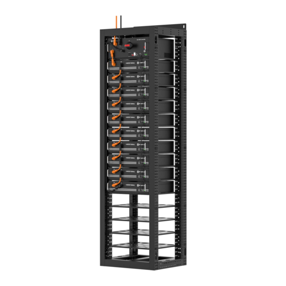
Page 25: Control Module (Bms) And All Battery Modules Install Into The Rack
3.5.4 Control Module (BMS) and all Battery Modules install into the Rack Install the buckle nuts. The position of nuts must meet the position of the control module (BMS) and all battery modules. Install the control module (BMS) and all battery modules in. Each module uses 4 screws to fix. ... -
Page 26: Power And Communication Cable Connection
Note: Power cable uses water-proofed connectors. It must keep pressing this Lock Button during pulling out the power plug. If there are more than 1 rack of PowerCube-X1/X2, there will require a MBMS on the top which aggregate information from all the BMS and communicate with inverter/PCS. - Page 27 CAN Communication Mode between MBMS and BMS Cable Diagram: Note: The 1 PowerCube-X1/X2 should be installed nearest to the MBMS.
-
Page 28: Add Switch Setting (Address Assignment)
3.6.3 ADD Switch Setting (Address Assignment) ADD Switch BMS is a 6 bit dial switches to manually distribute the communication address of the battery system. Nether position is OFF, means “0”. Upper position is ON, means “1”. 1 bit to 5 bit is for address, and the 6 bit dial switch support a 120Ω... -
Page 29: Multi Mbms Communication Mode
3.6.3.3 Multi MBMS Communication Mode In some project it configures multi Energy Storage Systems. In this case will have multi MBMS. The address of MBMS must follow <MBMS’s Address Configure Table> 3.6.4 System turns on Double check all the power cables and communication cables. Make sure the voltage of the PCS is same level with the battery system. - Page 30 Turn on the “POWER SWITCH”: ...
- Page 31 Warning: Due to the BMS positive pole internally do not contains isolating switch or breaker, only fuse and relay. The mains circuit cannot be manually cut-off while in power on stage. It`s mandatory to cut off the isolating switch or breaker externally firstly for safety concern. Avertissement: En raison du pôle positif BMS en interne, ne contient pas d'interrupteur d'isolement ou de disjoncteur, uniquement un fusible et un relais.
- Page 32 System start process: The battery string’s system will check itself, if work normal the battery string system will go to self- check mode. If the BMS and all battery modules are working normally, every status LED will lighting green, that’s mean self-check are pass.
- Page 33 Warning: If has failure during the self-check, must debug the failure then can start next step. En cas d’échec lors de l’auto-contrôle, vous devez déboguer l’échec pour pouvoir commencer à l’étape suivante. If the “STATUS” lamp shows red from beginning, it means has failure in the battery string, the Power Relays in BMS will switch ON, must debug at first.
- Page 34 (3) Switch the MBMS on after all the BMS turn on successful: And check whether MBMS is working. The “STATUS” lamp will light green. When the voltage difference between strings is smaller than the parameter, the battery string will do the parallel operation. Then the power relays in BMS will switch ON after 30 seconds. The “STATUS”...
-
Page 35: System Turns Off
When failure or before service, must turn the battery storage system off: (1) Soft-off the PCS through PCS’s control panel. (2) Turn off the switch between PCS and battery string (PowerCube-X1/X2), or turn off the power switch of PCS, to make sure no current transmission through battery string and PCS. -
Page 36: System Debug
System Debug This system debug is for BESS system (Battery Energy Storage System). BESS system can’t do the debug itself. It must operation with configured UPS, PCS and EMS system together. Debug Step Content Prepare of debug. Turn on the BESS system, refer to chapter 3. Before turn on the whole BESS system turn on the load is not allowed! Remark: Except the BESS, if other equipment have its own system turn on step, must follow its own system operation manual. -
Page 37: Maintenance
Maintenance 5.1 Trouble Shooting: Danger: The PowerCube-X1/X2 is a high voltage DC system, operated by qualified and authorized person only. PowerCube-X1/X2 est un système à courant continu à haute tension, opéré uniquement par le personnel qualifié et autorisé. Danger: Before check the failure, must check all the cables connection and the BESS system can turn on normally or not. - Page 38 -40℃. sampling failure. sampling module. Or change (Check through the monitor or this battery module. maintenance software.) Another failure Cell failure or electrical board Can’t find out failure point or failure. can’t check. Please contact with distributor or Pylontech.
-
Page 39: Replacement Of Main Component
5.2 Replacement of main component Danger: The PowerCube-X1/X2 is a high voltage DC system, operated by qualified and authorized person only. PowerCube-X1X2 est un système à courant continu à haute tension, opéré uniquement par le personnel qualifié et autorisé. Danger: Before replace the main component must shut off the maintenance battery string’s power. -
Page 40: Replacement Of Control Module (Bms)
Warning: Single battery module is 24kg/32kg. If without handling tools must more than 1 personnel to handling with it. If install in high place of the rack it must more than 2 personnel. Un module de batterie pèse kg/32kg. Sans outils de manipulation, il est nécessaire de plus de hommes pour manipuler avec lui. -
Page 41: Replacement Of 3 Rd Level Control Module (Mbms)
Caution: Before pull out the communication cables must mark the cable number, to avoid cable wrong sequence. Avant de débrancher les câbles de communication, vous devez marquer leurs numéros afin d'éviter toute séquence incorrecte. 5.2.3 Replacement of 3 level Control Module (MBMS) 5.2.3.1 Turn off the Power Switch. - Page 42 battery string abnormal SOC or not. 5.3.3 Cables Inspection: [Periodical Maintenance] Visual inspect all the cables of battery system. Check the cables has broken, aging, getting loose or not. 5.3.4 Balancing: [Periodical Maintenance] The battery strings will become unbalance if long time not be full charged. Solution: every 3 month should do the balancing maintenance (charge to full), normally it will been done automatically by the communication between system and external device.
-
Page 43: Storage Recommendations
Storage Recommendations For long-term storage (more than 3 months), the battery cells should be stored in the temperature range of 5~45℃, relative humidity <65% and contains no corrosive gas environment. The battery module should shelfed in range of 5~45℃, dry, clean and well ventilated environment. Before storage the battery should be charged to 50~55% SoC;... -
Page 44: Annex 1: Cable Connection Diagram
Annex 1: Cable connection diagram... -
Page 45: Annex 2: Installation And System Turn On Progress List
Annex 2: Installation and System Turn ON Progress List Tick after Item Remark completion The environment is meeting all technical requirements. 3.3.1 Cleaning 3.3.2 Temperature Refer to chapter ☐ 3.3.3 Radiating System 3.3.4 Heating System 3.3.5 Fire-extinguisher System 3.3.6 Grounding System Battery rack installed... -
Page 46: Annex 3: System Turn Off Progress List
Soft-off the PCS through PCS’s control panel. 3.6.5. Turn off the switch between PCS and this battery string ☐ Refer to chapter (PowerCube-X1/X2), or turn off the power switch of PCS, 3.6.5. to make sure no current through this battery string. Refer to chapter ☐... - Page 48 Pylon Technologies Co., Ltd. No. 73, Lane 887, ZuChongzhi Road, Zhangjiang Hi-Tech Park Pudong, Shanghai 201203, China T+86-21-51317699 | +86-21-51317698 service@pylontech.com.cn www.pylontech.com.cn...
Need help?
Do you have a question about the PowerCube-X1 and is the answer not in the manual?
Questions and answers