
Related Manuals for Pylontech Force-L2


Summary of Contents for Pylontech Force-L2
- Page 1 Lithium-Ion Phosphate Energy Storage System Force-L2 Operation Manual Information Version: 2.2 20P2FL0301...
-
Page 2: Table Of Contents
This manual introduces Force-L2 from Pylontech. Force-L2 is a 48V DC Lithium-Ion Phosphate Battery storage system. Please read this manual before you install the battery and follow the instruction carefully during the installation process. Any confusion, please contact Pylontech immediately for advice and clarification. - Page 3 3.5.3 System turns on ......................... 23 3.5.4 System turns off ......................... 24 4. SYSTEM DEBUG ..............................25 5. MAINTENANCE ..............................26 5.1 Trouble Shooting: ..........................26 5.2 Replacement of main component ..................27 5.2.1 Replacement of Battery Module ..................27 5.2.2 Replacement of Control Module (BMS) ................
-
Page 4: Safety Precautions
1. Safety Precautions Incorrect operation or work may cause: injury or death to the operator or a third party; damage to the system hardware and other properties belonging to the operator or a third party. Skills of Qualified Person Qualified personnel must have the following skills: Training in the installation and commissioning of the electrical system, as well as the dealing ... - Page 5 Symbol Warning electric shock! in label Symbol Do not place near flammable material in label Symbol Do not reverse connection the positive and negative. in label Symbol Do not place near open flame in label Symbol Do not place at the children and pet touchable area. in label Symbol Recycle label.
- Page 6 Warning: Whenever working on the battery, wear suitable personal protective equipment (PPE) such as rubber gloves, rubber boots and goggles. Warning: Force-L2 system working temperature range: 0℃~50℃; Optimum temperature: 18℃~ 28℃. Out of the working temperature range may cause the battery reduces the cycle of life even cause the battery system over / low temperature alarm or protection.
-
Page 7: Before Connecting
9) Do not paint any part of battery, include any internal or external components; 10) Do not connect battery with PV solar wiring directly; 11) Do not open, repair or disassemble the battery except staffs from Pylontech or authorized by Pylontech. We do not undertake any consequences or related responsibility which because of violation of safety operation or violating of design, production and equipment safety standards. -
Page 8: System Introduce
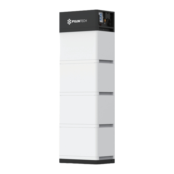
2. System Introduce 2.1 Product Introduce Force-L2 is a 48VDC battery storage system based on lithium iron phosphate battery, which is one of the new energy storage products developed and produced by Pylontech. It can be used to support reliable power for various types of equipment and systems. Force-L2 is especially suitable for those application scenes which required high power energy, limited installation space, restricted load-bearing and long cycle life. - Page 9 FORCE-L2 FORCE-L2 FORCE-L2 Product Type (48V148AH) (48V222AH) (48V296AH) Cell Technology Li-ion (LFP) Battery System Capacity(kWh) 7.10 10.65 14.20 Battery System Voltage (Vdc) Battery System Capacity (Ah) Battery Controller Name FC0048M-100S Battery Module Name FL4874M Battery Module Quantity(pcs) Battery Module Capacity(kWh) 3.552...
-
Page 10: Battery Module (Fl4874M)
2.2.2 Battery Module (FL4874M) Product Type FL4874M Cell Technology Li-ion (LFP) Battery Module Capacity (kWh) 3.552 Battery Module Voltage (Vdc) Battery Module Capacity (Ah) Battery Module Serial Cell Quantity (pcs) Battery Cell Voltage (Vdc) Battery Cell Capacity (AH) Dimension (W*D*H, mm) 450*296*296 Weight (kg) 35.5... -
Page 11: Control Module Fc0048M-100S (Internal Power Supply)
2.2.3 Control Module FC0048M-100S (internal power supply) Control Module (FC0048M-100S) Display Panel LED Button Short Press Display the LED panel for 20sec. Long Press When status LED fast flashes blue ●, loss the button, then it is (more than 115200 baud rate of RS485. 5sec) When status LED fast flashes orange ●, loss the button, then it is 9600 baud rate of RS485. - Page 12 Status Blue, flashing. Power Relay CLOSE. Alarm exist but can work continue. Blue, solid. Power Relay CLOSE. Normal. Power Relay OPEN. Normal protection, can recover on Orange, flashing. its own (Over Voltage, Under Temperature, etc.). Power Relay OPEN. Important protection, failure, lost Orange, solid.
- Page 13 Control Module (FC0048M-100S) Cable Panel Power Switch Switch A (1P). ON: the battery system’s controller able to turn on. OFF: whole system turns OFF. Switch B (2P). Main breaker. Caution: When the breaker is tripped off because of over current or short circuit, must wait more than 30min then can turn on it again, otherwise may cause the breaker damage.
-
Page 14: Definition Of Rj45 Port Pin
Maximum Transmitting power: 18dBm Wireless maximum output power: 20dBm Operating frequency: 2412-2472MHz Gain of antenna: Max 3dBi Modulation system: DBPSK/DQPSK/CCK(DSSS) BPSK/QPSK/16QAM/64QAM(OFDM) Modulating Repetition: 1Mbps/2Mbps/5.5Mbps/11Mbps(DSSS) 6Mbps/9 Mbps/12 Mbps/18 Mbps/24 Mbps/36 Mbps/48 Mbps/54 Mbps(OFDM) MCS0~MCS7(802.1 1n 20MHz) Channel spacing:5MHZ Type of antenna: 2.4G IPEX-SMA Antenna Power Terminal (+/-) Connect power cables of battery system with Inverter. -
Page 15: System Diagram
CANH CANL RS485A RS485B Note: Other Pin must be NULL, if not may influence the communication of system. 2.3 System Diagram 12 / 31... -
Page 16: Installation
3. Installation 3.1 Tools The following tools are required to install the battery pack: Wire Cutter Crimping Modular Plier Cable Ties Screw Driver Set Electric Screw Driver Adjustable Wrench Sleeve Piece Multimeter NOTE Use properly insulated tools to prevent accidental electric shock or short circuits. If insulated tools are not available, cover the entire exposed metal surfaces with available insulated alternatives, except their tips, with electrical tape. -
Page 17: System Working Environments Checking
In could area the heating system is required. Force-L2 system must not be immersed in water. Cannot be placed the battery base in rain or other water sources. As a suggestion, the base’s height should >300mm above the ground. -
Page 18: Mounting And Installation Of The Base
3.4.4 Mounting and installation of the base The base must be fixed installed on the basement with 4pcs M8×80 foundation bolts. Battery rack basement holes bitmap (unit: mm): 15 / 31... -
Page 19: Battery Modules And Control Module (Bms) Pile Up
3.4.5 Battery Modules and Control Module (BMS) pile up Handle above the red marked edgings of the both side of these battery modules and control module (BMS). Caution: If hands under this red marked side, hands will get hurt. 16 / 31... -
Page 20: Installation Of The Fixed Metal Bracket For The System
3.4.6 Installation of the fixed metal bracket for the system In control module’s package, there are 2pcs Controller-2-modules-bracket, and 2pcs Base-2-modules-bracket. Fix these metal brackets at the both back side corners. 17 / 31... -
Page 21: Locking Of Control Module's Fix Screw Of Left And Right Side
3.4.7 Locking of control module’s fix screw of left and right side And dismantle the Protection Cover of the Power Terminals. 18 / 31... -
Page 22: Cables Connection
3.5 Cables connection Connect the power Terminal +/- to the inverter or the DC switches. Danger: All the plugs and sockets of the power cables must be not reverse connection. Danger: Do not short circuit or reserved connection of the battery system’s positive and negative port. - Page 23 Connect the communication cables between battery stacks: one by one from Stack last to the Stack 1 (from LinkPort0 to Linkport1). Connect the communication cable between master battery stack (Stack 1) to the inverter. The length of communication cable between stacks must ≤2m. ...
-
Page 24: Grounding
3.5.1 Grounding The Force-L2 modules’ grounding cable on the Cable Panel’s grounding point. Or the M6 grounding bolt on the frame base. Grounding cable must ≥6AWG. The cable shall be copper with yellow-green color. 21 / 31... -
Page 25: Cables
3.5.2 Cables Note: Power cable uses water-proofed connectors. Note: Communication cable uses RJ45 connector and water-proofed cover matched with controller connection port. For inverter follow same pin definition, the communication cable can be used directly. For inverter with different pin definition or not using RJ45 port, when change the connecter, please check the pin order and make sure undefined pin is not connected with each other and not connected to the inverter. -
Page 26: System Turns On
3.5.3 System turns on Warning: Double check all the power cables and communication cables. Make sure the voltage of the inverter is same level with the battery system before connection. Check all the power switch of every battery system is OFF. System turns on step: 1) Check all cables are connected rightly. -
Page 27: System Turns Off
4) Turn off switch between battery and inverter Under emergency condition, it is suggested to turn off switch between battery system and inverter first. NOTE After installation, DO NOT forget to register online for full warranty: www.pylontech.com.cn/service/support 24 / 31... -
Page 28: System Debug
4. System Debug This system debug is for BESS system (Battery Energy Storage System). BESS system can’t do the debug itself. It must operation with configured inverter, UPS and EMS system together. Debug Step Content Prepare of debug. Turn on the BESS system, refer to chapter 3. The battery system will close relay and has power output. -
Page 29: Maintenance
5. Maintenance 5.1 Trouble Shooting: Check the environment first, Problem Possible Reason Solution No power output, no Press start button too short. Press at least longer than 2 led on. seconds. The button battery in controller Change controller is missing or failure. module The power supply in controller is failure. -
Page 30: Replacement Of Main Component
environment and wait until protection release. Temperature normal: make sure no power cable connected, try black start operation. If works, monitor the voltage at dc terminal, if too low then turn off and charge the system. If do not response the black start, use debug tool for further check. - Page 31 5.2.1.5 Move the control module and each battery module one by one. Handle above the red marked edgings of the both side of these battery modules and control module (BMS). Caution: If hands under this red marked side, hands will get hurt. Warning: Single battery module is 35kg.
-
Page 32: Replacement Of Control Module (Bms)
5.2.2 Replacement of Control Module (BMS) 5.2.2.1 Turn off the whole battery string’s power. Must confirm the D+ and D- terminal are without power. The turn off progress refer to chapter 3.6.5. 5.2.2.2 Dismantle the Protection Cover of the Power Terminals. -
Page 33: Battery Maintenance
5.2.2.7 Install back Grounding Cable, Communication Cable and the D+ and D- Power Cable. 5.2.2.8 Turn on this battery string. Refer to chapter 3.6. 5.2.2.9 After debug must install the Protection Cover of the Power Terminals back. 5.3 Battery Maintenance 5.3.1 Voltage Inspection: [Periodical Maintenance] Check the voltage of battery system through the monitor system. -
Page 34: Storage Recommendations
2. In particular, special rules for the carriage of goods on the road and the current dangerous goods law, specifically ADR (European Convention on the International Carriage of Dangerous Goods by Road), as amended, must be observed. Any further questions, please contact Pylontech: service@pylontech.com.cn 31 / 31... - Page 35 Pylon Technologies Co., Ltd. No. 73, Lane 887, ZuChongzhi Road, Zhangjiang Hi-Tech Park Pudong, Shanghai 201203, China +86-21-51317699 | +86-21-51317698 service@pylontech.com.cn www.pylontech.com.cn...
Need help?
Do you have a question about the Force-L2 and is the answer not in the manual?
Questions and answers